element14 Community
element14 Community
    Register Log In
  • Site
  • Search
  • Log In Register
  • About Us
  • Community Hub
    Community Hub
    • What's New on element14
    • Feedback and Support
    • Benefits of Membership
    • Personal Blogs
    • Members Area
    • Achievement Levels
  • Learn
    Learn
    • Ask an Expert
    • eBooks
    • element14 presents
    • Learning Center
    • Tech Spotlight
    • STEM Academy
    • Webinars, Training and Events
    • Learning Groups
  • Technologies
    Technologies
    • 3D Printing
    • FPGA
    • Industrial Automation
    • Internet of Things
    • Power & Energy
    • Sensors
    • Technology Groups
  • Challenges & Projects
    Challenges & Projects
    • Design Challenges
    • element14 presents Projects
    • Project14
    • Arduino Projects
    • Raspberry Pi Projects
    • Project Groups
  • Products
    Products
    • Arduino
    • Avnet Boards Community
    • Dev Tools
    • Manufacturers
    • Multicomp Pro
    • Product Groups
    • Raspberry Pi
    • RoadTests & Reviews
  • Store
    Store
    • Visit Your Store
    • Choose another store...
      • Europe
      •  Austria (German)
      •  Belgium (Dutch, French)
      •  Bulgaria (Bulgarian)
      •  Czech Republic (Czech)
      •  Denmark (Danish)
      •  Estonia (Estonian)
      •  Finland (Finnish)
      •  France (French)
      •  Germany (German)
      •  Hungary (Hungarian)
      •  Ireland
      •  Israel
      •  Italy (Italian)
      •  Latvia (Latvian)
      •  
      •  Lithuania (Lithuanian)
      •  Netherlands (Dutch)
      •  Norway (Norwegian)
      •  Poland (Polish)
      •  Portugal (Portuguese)
      •  Romania (Romanian)
      •  Russia (Russian)
      •  Slovakia (Slovak)
      •  Slovenia (Slovenian)
      •  Spain (Spanish)
      •  Sweden (Swedish)
      •  Switzerland(German, French)
      •  Turkey (Turkish)
      •  United Kingdom
      • Asia Pacific
      •  Australia
      •  China
      •  Hong Kong
      •  India
      •  Korea (Korean)
      •  Malaysia
      •  New Zealand
      •  Philippines
      •  Singapore
      •  Taiwan
      •  Thailand (Thai)
      • Americas
      •  Brazil (Portuguese)
      •  Canada
      •  Mexico (Spanish)
      •  United States
      Can't find the country/region you're looking for? Visit our export site or find a local distributor.
  • Translate
  • Profile
  • Settings
Test & Tools
  • Technologies
  • More
Test & Tools
Blog Building Solderable In-Circuit Oscilloscope Probes
  • Blog
  • Forum
  • Documents
  • Files
  • Members
  • Mentions
  • Sub-Groups
  • Tags
  • More
  • Cancel
  • New
Join Test & Tools to participate - click to join for free!
  • Share
  • More
  • Cancel
Group Actions
  • Group RSS
  • More
  • Cancel
Engagement
  • Author Author: shabaz
  • Date Created: 10 Feb 2021 12:28 AM Date Created
  • Views 19263 views
  • Likes 17 likes
  • Comments 37 comments
  • oscilloscope probe
Related
Recommended

Building Solderable In-Circuit Oscilloscope Probes

shabaz
shabaz
10 Feb 2021

  • Introduction
  • Why not just use Coax Cable
  • How Do Probes Work?
    • ‘Normal’ Passive Probes
    • Resistive Probes
  • Building It
  • Using It
  • Comparison with Other Probing Methods
  • Summary


Introduction

The probes attached to oscilloscopes are fundamental to getting useful captures and measurements from the ‘scope. The normally seen ‘scope probes (technically they’re called passive probes) have a special construction that is not easy to DIY; it’s best to purchase these. They have a distributed resistance running all along the wire (it is not ‘normal’ coax!) and without that the oscilloscope will display a distorted signal.


Many such passive probes come with a pointy tip and with attachments such as grippers. The probe end can sometimes be inserted into sockets too. However, it is rarer for supplied probes to come with a solderable wire attachment (although some probes do come with that). This blog post documents an experiment to build solderable probes, the idea being that the probes can be quickly tacked with solder directly onto the board under test.

image


I had written some notes for building custom probes several months ago, but I’d not got around to documenting it because I did not have a decent way to test it all. Since then, Building a Fast Edge Square Wave Generator allowed me to collect some measurements.


This blog post may be useful for those who need low-cost ‘scope probes, or for those who want solderable probes for attaching to a circuit board, temporarily or even semi-permanently. For another technique for using probes, see DIY $10 Solder-in Oscilloscope Probe


It can sometimes make a huge difference to usability, not needing to hold probes in position manually! To cut a long story short, all it entails is soldering a 950 ohm (or 953 ohm - easier to find!) resistor inline with the center conductor of a coax cable. It is inside the yellow pod in the photo below. Connect the other end to your 'scope and set it to 50 ohms, and that's pretty much it : )

image


If you’ve recently purchased an oscilloscope, hopefully, it came with ‘scope probes but if it didn’t, you can make these! However, there are limitations; the probes described in this blog post have an impedance of 1 kohm. This is lower than typical passive probes that come with oscilloscopes, so it may load the signal to be measured too much. The best approach to using the solderable probes described in this blog post would be to first briefly check with a normal passive probe to see what the signal should look like.


Why not just use Coax Cable

One school of thought could be to get a coax cable, attach one end to the ‘scope and the other end to the signal on the device under test. Ordinary coax cable can be used in such a scenario but only if the signal is intended for a 50 ohm load, and the ‘scope is set accordingly to a 50 ohm termination.


It is best to avoid ‘unusual’ attachments like BNC-to-banana or BNC-to-alligator, or ordinary coax cable, unless you’re very sure of what you’re expecting to measure, otherwise, one will get burned sooner or later with confusing ‘scope trace results.


If the oscilloscope is not set to 50 ohms load, then fast-changing signals will appear distorted; there is an explanation for this here.

Also, it’s good to avoid setting the ‘scope to 50 ohms unless you’re really sure that the signal source can handle this low impedance, and that the ‘scope input can handle the power going into it’s internal 50 ohm resistor - to prevent blowing up the 'scope input.


Some oscilloscopes do not have a 50 ohm input. For such ‘scopes with up to around 200 MHz bandwidth, it is ok to use either an inline 50 ohm resistance or a BNC T-piece with 50 ohm terminator. Note however that nearly all low-cost 50 ohm BNC terminators are designed for old-school local area network or LAN connections and will not work very well; it’s best to buy a terminator specifically intended for operation at high frequencies, or make your own!).


How Do Probes Work?

‘Normal’ Passive Probes

Normal oscilloscope probes (also known as 10X or 100X passive probes) use a specialized, custom cable for ultra-low capacitance. This is needed in order not to attenuate the signal too much at high frequencies. At either end of the cable, passive components are used to create a potential divider circuit, so that the circuit under test is not impacted much when the probe and ‘scope are attached to it. The potential divider circuit is a bit specialized because it includes a compensation capacitance within the divider, so that the (unwanted but inevitable) ‘scope input capacitance, combined with the probe cable capacitance, does not act as a low-pass filter. This type of ‘scope probe is better purchased than DIY’d!


Resistive Probes

An alternative type of probe, known as a resistive probe, has a simpler topology. It relies on normal coax cable. Typical ’50 ohm’ labelled coax cable has a property that, if the far end of it is connected to a 50 ohm resistor, means that any signal input at the other end will also see a pure 50 ohm resistance and actually won’t see any reactance, regardless of the capacitance and inductance of the coax. As a result, the potential divider can be greatly simplified compared to a conventional passive probe! (The feature of coax that causes this behavior is known as its transmission line property, and that property enables many operations transporting signals in systems, especially communications circuits, networks and computers).


Resistive probes are described in online and offline literature. The Art of Electronics suggests using a 950 ohm (or 953 ohm since that is an E24 value) resistor in series with the coax cable, at the signal end. The potential divider formed with the 50 ohm oscilloscope input setting, therefore, reduces the voltage by 20 times. The resistor value is a compromise; too high a resistance and the signal is attenuated too much for the oscilloscope to display well, and too low a resistance and the circuit under test gets loaded too much. Since a resistor is not perfectly resistive and has some capacitance and inductance too, the construction of the resistor can have an affect too, and the impact of that may differ depending on the resistance value as well.


Using a 950 ohm resistance, the circuit will see a 1 kohm load when the far end of the probe is terminated with a 50 ohm resistor. 1 kohm isn’t great for all scenarios, however for many circuits, especially logic gate outputs, it can be acceptable to attach to such a load.


With microcontroller and digital circuits, it can often be necessary to probe several connections for serial busses, and it could be awkward to use many probe clips while debugging. A solderable option for the probes could be attractive for that scenario.


Building It

Construction can be very straightforward. Any 50 ohm coax cable can be used. Attach a BNC connector to one end. If you don't feel comfortable doing that, it is possible to purchase BNC-to-BNC cables and cut in half, or chop off one end.


For the resistor, a 1% tolerance 953 ohm thick film (not thin-film) resistor can be used, or perhaps a 5% tolerance 1 kohm resistor (many could be purchased, and individually measured to select the ones closest to 950 ohm).


For my implementation, I used RG-178 coax. If you’re unfamiliar with it, it’s one of the most useful coax types for electronics labs as general-purpose hookup-coax, because it is so easy to work with, and excellent for short connections.  It is thin (1.8 mm overall diameter) and the outer insulator is easily removed by lightly scoring with a knife, bending the coax slightly to tear at the score, and then gripping with wire cutters and sliding it off. Another excellent property is that it’s almost impossible to melt the inner insulator (dielectric) when soldering.


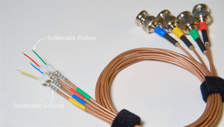
I wanted to make several of these probes, so I used heat-shrink tubing at each end for color-coding. I used 2.5 mm2 ferrules to terminate the outer braid, however, it’s not necessary; you could just spin the braid around the outer insulation and tin it with solder to form a circular termination, all ready for attaching a ground cable. Since the coax is so thin, the outer termination could also be directly soldered to the nearest ground point or ground plane on the circuit board under test.


The diagram below contains measurements in case anyone wants to assemble it in a similar way, to get comparable results as I got. I'm not saying my method was good or bad; it's just one data point, so experimentation could improve the results further.

image


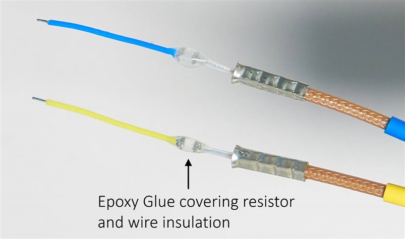
I used an 0805-sized 953 ohm thick film resistor, and fairly thin 30AWG stranded PTFE-insulated wire. This will allow me to solder the probes even in fairly dense locations on a PCB.

image


The resistor and the connections to it were covered in ‘instant’ epoxy glue (it sets in a minute or two), and I tried to get glue over the insulation of the wire too, to secure it all properly. Maybe this step isn’t required.

image


Next, to make the colored plastic blobs, Polydoh was used. If you’ve not used it before, it is like a manual version of 3D printing plastic; it melts at a low temperature and can be formed with ease. It comes as a bag of white granules/pellets and can be purchased bundled with pigment granules too, to be mixed in. It is really cheap – about $15 for a bag containing thousands of granules.

image


Ordinarily, the granules are supposed to be used with boiling water, but I didn’t want to get my resistor wet, so an alternative procedure was used. I took two granules and placed them on a surface (I used a metal block) and heated it with a hot air tool. After a few seconds, it was possible to place the wire and resistor between the two granules and fold it all around into a kind of pod or egg-shape, using bare fingers (it doesn’t burn the fingers, just feels slightly hot briefly). If it hardens too soon before it is fully shaped, then it can be re-heated with the hot air tool.

image


If you don’t want white blobs and want to color-co-ordinate with the ‘scope channel colors, then instead of just heating two granules, add a single pigment granule too, and then mash the molten color into the molten granules with fingers, and then (because it will have cooled and solidified) place back on the block and re-heat, and then wrap it around the resistor and form the blob. It’s really easy!


Using It

For peace of mind, as mentioned earlier, if you’re unsure what sort of signal levels to expect, a normal passive probe should be first used to be aware of what the signal should approximately look like.


To use the resistive probe, if your oscilloscope has a 50 ohm termination setting, that needs to be enabled. Otherwise, a 50 ohm terminator and a BNC T-piece is required for each probe. This is mandatory.


Next, set the oscilloscope scaling to 20X. If the oscilloscope does not support such a setting, then the scaling will need to be done mentally because the displayed voltage levels will be scaled down by that factor.


Solder on the probe to the circuit under test, attach the probe to the ‘scope and power up the circuit under test!


Comparison with Other Probing Methods

For a test signal, I used a square wave generator circuit (see Building a Fast Edge Square Wave Generator  ). The reference signal (captured with a plain 50 ohm coax connection to the ‘scope) is shown at that blog post, and will be used for comparison purposes as a near-ideal capture.


I tested three different probing methods:


  1. Simple plain coax connected to the square wave generator, and the oscilloscope set to its normal 1 Mohm setting. This will be a bad method as will be visible in the ‘scope traces.
  2. The home-made resistive probe, connected to the oscilloscope set to 50 ohm input
  3. Active FET probe. This probe should give good results but is a pricey option. It will be good to compare the results.


The photos below show the three different methods. For all three methods, the square wave generator output was directed into a 50 ohm load, which can be seen screwed onto the SMA connector at the top of each photo.

image


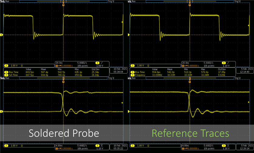
The oscilloscope traces below show the results for each of the probing methods. The reference trace (from the square wave generator blog post) is shown on the right for easy comparison. The coax method was, as expected, bad. Coax 1 and Coax 2 were attempts with different lengths of coax, and it made a difference, again as expected. In summary, both Coax 1 and Coax 2 look bad, with Coax 2 happening to look extremely bad. This is the danger of just using coax like this; the result can look extremely distorted.

image


The resistive probe results are shown below. There is a small anomaly visible about 8 nanoseconds from the time of the rising edge, but aside from that the result looks fairly similar.

image


The result from the active probe is shown below. There are a couple of small differences here and there, but generally the trace looks similar to the reference.

image


Summary

Solderable ‘resistive’ oscilloscope probes are easy to create, and although they won’t be suitable for all circuits, they can be handy for attaching to awkward locations for some circuits under test. The results show there really isn’t much difference between the expected reference trace, and the result with the solderable probe looks fairly good! It is not as general-purpose as a normal passive probe nor as high impedance as an active probe. The resistive probe will not be suitable for all purposes due to the 1 kohm impedance it presents to circuits, however, it could be handy from time to time. As mentioned earlier in the blog post, another solderable option is to try to attach the normal passive probe into a circuit using a PCB probe socket.


Thanks for reading!

  • Sign in to reply

Top Comments

  • baldengineer
    baldengineer over 4 years ago +6
    Excellent work! I've been thinking about how to solder passive probes into a circuit for while. (PMK makes an accessory for it, but almost no scope manufacturer that uses their probes stocks or sells it…
  • hlipka
    hlipka over 4 years ago +6
    Cool idea, I need to try that. I would try to use some heat shrink around the SMD resistor instead of epoxy, this might give better stability with the wires (and can also double as color-coding).
  • kmikemoo
    kmikemoo over 4 years ago +5
    Brilliant and very cool! Thanks for sharing.
Parents
  • jc2048
    jc2048 over 4 years ago

    This is interesting. I've seen the idea mentioned, but never tried it myself, so it's very useful to see your results.


    Resistive probes are described in online and offline literature.

    Howard Johnson and Martin Graham, in 'High-Speed Digital Design', simply go for a 1k resistor (ie 21:1) and use the oscilloscope to turn that back into sensible values [presumably they had a fairly good oscilloscope to play with].


    Henry Ott has an interesting variation on the theme in 'Electromagnetic Compatibility Engineering'. He suggests two of them, side-by-side, with 450R resistors (so 10:1), to make a differential probe for looking at differences between ground signals in separate parts of a plane (two 50R input channels, with subtraction for the differencing). He tacks the outer of the shields together every few inches [there's no connection for the screen at the probe end - the return currents just run around the end to form their own loop, if you see what I mean - if this isn't very clear, say, and I'll draw it - I don't want to reproduce his picture because it's still in print]. He also suggests using it with a 'high-frequency 180 degree combiner' to feed it to a single-ended spectrum analyser [that part looks very radio-engineerish to me, because he starts going on about insertion losses, and that kind of thing] which is probably more up your street than mine [as I don't even have a spectrum analyser].


    One reason 20:1 might work well is to do with the kind of capacitance you get at the input of the oscilloscope. For my scope, it's 11.5pF. If the end-to-end capacitance of the probe resistor is of the order of 0.5pF, then that's in the right kind of area for a 20:1 capacitive divider to match the resistive one. If you wanted to experiment, simply trying 1206, 0805, and 0604, and seeing which worked best might be one approach, though the difference might be too slight to see. Just a thought.

    • Cancel
    • Vote Up +5 Vote Down
    • Sign in to reply
    • More
    • Cancel
  • shabaz
    shabaz over 4 years ago in reply to jc2048

    Hi Jon,


    Thanks for the info!

    jc2048  wrote:


    One reason 20:1 might work well is to do with the kind of capacitance you get at the input of the oscilloscope. For my scope, it's 11.5pF. If the end-to-end capacitance of the probe resistor is of the order of 0.5pF, then that's in the right kind of area for a 20:1 capacitive divider to match the resistive one. If you wanted to experiment, simply trying 1206, 0805, and 0604, and seeing which worked best might be one approach, though the difference might be too slight to see. Just a thought.

    That makes sense, I hadn't thought of the 'scope's input capacitance on the 1Mohm setting which would get paralleled up with the 50 ohm terminator. I did think of trying different size resistors, but was sufficiently surprised the first attempt (0805) worked quite well, so didn't get around to trying others (I didn't have any larger resistor anyway). The 1206 would be interesting to try!


    Henry Ott has an interesting variation on the theme in 'Electromagnetic Compatibility Engineering'. He suggests two of them, side-by-side, with 450R resistors (so 10:1), to make a differential probe for looking at differences between ground signals in separate parts of a plane (two 50R input channels, with subtraction for the differencing). He tacks the outer of the shields together every few inches [there's no connection for the screen at the probe end - the return currents just run around the end to form their own loop, if you see what I mean - if this isn't very clear, say, and I'll draw it - I don't want to reproduce his picture because it's still in print]. He also suggests using it with a 'high-frequency 180 degree combiner' to feed it to a single-ended spectrum analyser [that part looks very radio-engineerish to me, because he starts going on about insertion losses, and that kind of thing] which is probably more up your street than mine [as I don't even have a spectrum analyser].

    I think  I see what you mean! I'll try to dig up the document you mention, just to be 100% sure, but I think I can follow your explanation. I do have a splitter/combiner (was just using it today for a specific exercise) mine covers 5 MHz to 200 MHz range, it is Minicircuits PMT-1+ (PDF datasheet).  I wish I had one that covered a higher range, but it's so expensive ordering from Minicircuits (nothing is cheap there). It is an interesting device, it could be worth also occasionally checking ebay for these too. You're right it's popular for radio uses, but it can also be used with a 'scope instead of a spectrum analyzer, although for that use-case the spectrum analyzer would be needed for the sensitivity. It can be used to check for things like delays i.e. phase differences between the two inputs, by seeing how much the output changes by. Or, it can be used to generate two out of phase signals, if the same signal is input to both inputs. It's quite a versatile device. I'll try to assemble something like this at some point (likely in a couple of weeks time) because it sounds super-useful! Maybe it can be used with a 'scope with an amplifier. I'll experiment a bit. It seems a really clever concept, I would never have thought to apply two 450 ohm probes in this way.

    • Cancel
    • Vote Up +3 Vote Down
    • Sign in to reply
    • More
    • Cancel
  • Jan Cumps
    Jan Cumps over 4 years ago in reply to jc2048

    Ah I get it.

    so you might want a second opinion

    I'm happy with this one :)

    • Cancel
    • Vote Up +4 Vote Down
    • Sign in to reply
    • More
    • Cancel
  • shabaz
    shabaz over 4 years ago in reply to Jan Cumps

    A kind of summarized way to see it (a way doesn't really explain how, just explains the result, so mine is not as good an explanation as Jon's which is correctly concerned with the wave propagation, skin effect and all that goes into it), is that the end result is that it's behaving like a common-mode choke that happens to have just one turn.


    Depending on who you speak to, it goes by different names - wireless users might call it a 'balun' instead, whereas other engineers would refer to it as a choke, plus the description of how it works changes, depending on the way it's put together and frequencies being referred to. For example if it wasn't coax but just twisted pair, then although the same fundamental mechanisms that Jon describes are at play, people might explain it differently because twisted pair has no shield to use in the explanation.


    A simplistic end-result but subset way for RF (not really for EMC people who might also be dealing with wires that are not a transmission line), is to just assume that if it's a transmission line (which it is in this particular application where high frequencies are being used and 50 ohm coax is deliberately being used to match with the source and with the sink) then the intended differential-mode content will still get through by virtue of the distributed LC causing wave propagation etc (I'm not familiar with all the subtleties), but any stuff picked up by the braid won't (technically this is common-mode just as EMC people would also describe it, but a bit harder to visualize with this differential probe, at least for me; it's easier to see with a single coax with the braid and centre conductor connected through a low matching impedance which it would normally be, where if you didn't have the ferrite then anything picked up by the outer braid would also make its way onto the centre conductor, i.e. common-mode.


    A bit unrelated but still semi-related, the coax-in-ferrite is super-popular for RF uses, because by manipulating the arrangement (e.g. having two coax cables) and connecting the ends appropriately, you can make interesting components, all relying on at least a couple of things: (1) the signal gets through (i.e. differential mode), and (2) for low frequencies, where the transmission line effect isn't occurring, the signal gets through using magnetic coupling (which usually can get through the coax shield anyway). Also please take my explanation with a pinch of salt too, but also be wary of Internet sources, a lot of them are plain wrong, even if I can't do a better explanation in terms of theory. There are excellent sources from (say) excellent ham radio people who have put the effort in to explain with detail, but poor and incorrect sources from other ham users I'm sorry to say. I found this for stuff on how to wind transformers for the Project14 RF project.. a sizeable percentage of sources on the Internet were using misleading info and incorrect diagrams. Here we all scrutinize and comment if we spot issues, but other Internet sources can be so one-way, material published and never corrected for a decade : ).

    • Cancel
    • Vote Up +4 Vote Down
    • Sign in to reply
    • More
    • Cancel
  • Jan Cumps
    Jan Cumps over 4 years ago in reply to shabaz

    What my brain missed, was that the signal copper lines physically go through the ferrite core (the one winding) , but that in reality the signal doesn't see it because of the shielding.

    • Cancel
    • Vote Up +4 Vote Down
    • Sign in to reply
    • More
    • Cancel
  • shabaz
    shabaz over 4 years ago in reply to jc2048

    I think I understand how to use it now : ) This time I reduced the length of the exposed probe. There is about 65 mm of braid that is no longer joined at the ends. I used a real board, this was a 2-layer audio-type amplifier board, with entire ground plane on the underside, and also stitched to planes on the top side, all are ground planes, no other power plane. The board was designed to have an input capacitor, and amplifier chip with associated components, and an output capacitor. For this bare board, the input and output capacitor locations are jumpered with bare wire links (see orange and blue arrows). The amplifier chip is bypassed with a purple wire. The yellow circle indicates the position of a 50 ohm load resistor. The signal from the signal generator traverses the path shown by yellow arrows, until finally it drops into the ground plane at the green arrow location.


    The signal generator is set to 35 MHz, -10 dBm. When I connect these differential probes across the wire links (orange or blue arrows), I see -65 dBm on the spectrum analyzer in both cases. When I connect the probes to the green circle locations, which are ground plane (I scraped off the solder resist there), I see -88 dBm. It's quite neat! Of course really for a like-for-like comparison, the distance between the probes should be approximately kept similar across all measurements, I don't think it's critical at this frequency at all). And if it was a good ground plane then the distance between the probes should still result in a measurement close to the noise floor regardless of distance.


    I'm thinking this should be made also with small sharp probes with insulation around them, like miniaturized multimeter probes, since this use-case involves moving the probes around a lot, rather than always wanting them soldered into a position (although soldering will give the best results by eliminating hands holding probes from causing an effect).

    This has been an interesting experiment.


    image

    • Cancel
    • Vote Up +4 Vote Down
    • Sign in to reply
    • More
    • Cancel
  • genebren
    genebren over 4 years ago in reply to shabaz

    Very cool.  Maybe jw0752 super sharp probe tips could be modified to work.

    • Cancel
    • Vote Up +3 Vote Down
    • Sign in to reply
    • More
    • Cancel
Comment
  • genebren
    genebren over 4 years ago in reply to shabaz

    Very cool.  Maybe jw0752 super sharp probe tips could be modified to work.

    • Cancel
    • Vote Up +3 Vote Down
    • Sign in to reply
    • More
    • Cancel
Children
No Data
element14 Community

element14 is the first online community specifically for engineers. Connect with your peers and get expert answers to your questions.

  • Members
  • Learn
  • Technologies
  • Challenges & Projects
  • Products
  • Store
  • About Us
  • Feedback & Support
  • FAQs
  • Terms of Use
  • Privacy Policy
  • Legal and Copyright Notices
  • Sitemap
  • Cookies

An Avnet Company © 2025 Premier Farnell Limited. All Rights Reserved.

Premier Farnell Ltd, registered in England and Wales (no 00876412), registered office: Farnell House, Forge Lane, Leeds LS12 2NE.

ICP 备案号 10220084.

Follow element14

  • X
  • Facebook
  • linkedin
  • YouTube