element14 Community
element14 Community
    Register Log In
  • Site
  • Search
  • Log In Register
  • About Us
  • Community Hub
    Community Hub
    • What's New on element14
    • Feedback and Support
    • Benefits of Membership
    • Personal Blogs
    • Members Area
    • Achievement Levels
  • Learn
    Learn
    • Ask an Expert
    • eBooks
    • element14 presents
    • Learning Center
    • Tech Spotlight
    • STEM Academy
    • Webinars, Training and Events
    • Learning Groups
  • Technologies
    Technologies
    • 3D Printing
    • FPGA
    • Industrial Automation
    • Internet of Things
    • Power & Energy
    • Sensors
    • Technology Groups
  • Challenges & Projects
    Challenges & Projects
    • Design Challenges
    • element14 presents Projects
    • Project14
    • Arduino Projects
    • Raspberry Pi Projects
    • Project Groups
  • Products
    Products
    • Arduino
    • Avnet Boards Community
    • Dev Tools
    • Manufacturers
    • Multicomp Pro
    • Product Groups
    • Raspberry Pi
    • RoadTests & Reviews
  • Store
    Store
    • Visit Your Store
    • Choose another store...
      • Europe
      •  Austria (German)
      •  Belgium (Dutch, French)
      •  Bulgaria (Bulgarian)
      •  Czech Republic (Czech)
      •  Denmark (Danish)
      •  Estonia (Estonian)
      •  Finland (Finnish)
      •  France (French)
      •  Germany (German)
      •  Hungary (Hungarian)
      •  Ireland
      •  Israel
      •  Italy (Italian)
      •  Latvia (Latvian)
      •  
      •  Lithuania (Lithuanian)
      •  Netherlands (Dutch)
      •  Norway (Norwegian)
      •  Poland (Polish)
      •  Portugal (Portuguese)
      •  Romania (Romanian)
      •  Russia (Russian)
      •  Slovakia (Slovak)
      •  Slovenia (Slovenian)
      •  Spain (Spanish)
      •  Sweden (Swedish)
      •  Switzerland(German, French)
      •  Turkey (Turkish)
      •  United Kingdom
      • Asia Pacific
      •  Australia
      •  China
      •  Hong Kong
      •  India
      •  Korea (Korean)
      •  Malaysia
      •  New Zealand
      •  Philippines
      •  Singapore
      •  Taiwan
      •  Thailand (Thai)
      • Americas
      •  Brazil (Portuguese)
      •  Canada
      •  Mexico (Spanish)
      •  United States
      Can't find the country/region you're looking for? Visit our export site or find a local distributor.
  • Translate
  • Profile
  • Settings
Test & Tools
  • Technologies
  • More
Test & Tools
Blog Circuit Prototyping using Copper Tape
  • Blog
  • Forum
  • Documents
  • Files
  • Members
  • Mentions
  • Sub-Groups
  • Tags
  • More
  • Cancel
  • New
Join Test & Tools to participate - click to join for free!
  • Share
  • More
  • Cancel
Group Actions
  • Group RSS
  • More
  • Cancel
Engagement
  • Author Author: shabaz
  • Date Created: 6 Feb 2021 10:17 PM Date Created
  • Views 9180 views
  • Likes 14 likes
  • Comments 10 comments
  • copper tape
  • soldering tips
  • smt soldering
  • polyimide tape
  • prototyping
  • kapton tape
  • surface mount soldering
  • surface mount
Related
Recommended

Circuit Prototyping using Copper Tape

shabaz
shabaz
6 Feb 2021

This blog post walks through one method for prototyping electrical circuits.  It revolves around using prototyping boards, copper tape, and thin insulating tapes and wires.

Here's an example:

image

The example above was built on copper-clad board, but other types of boards can be used too:

image

The copper-clad board is great for whenever a ground plane is desired. It comes in single-sided and double-sided variants. I use double-sided which can be sometimes convenient.

The tools and consumables required are shown in the photos below. What is not shown is the soldering iron and the head-mounted magnifier, and both of those are important too. I used a 1 mm tip soldering iron (even for soldering to the large area of copper), but this requires an iron with the heating element within the tip itself probably. For soldering irons with an indirectly heated tip, a larger tip will likely be needed.

image

The wire strippers and wire are quite special. The Kynar or Tefzel or PVDF wiresPVDF wires have insulation that will not shrink or melt when soldered. The wire strippers can be used to strip extremely tiny lengths of such 30 AWG sized wire. In the photos below, the wires were 15mm length, and after stripping around 2.5 mm from each end, only around 10 mm of insulation remained. This isn't easy to do with other wire strippers. With the Stripmaster Lite 45-672Stripmaster Lite 45-672 tool, such small wires can be stripped by holding the wire with tweezers and inserting into the tool. The wire and wire strippers are simply brilliant for prototyping. Here's another example, this time showing how to solder pads underneath a chip or module. The wire is silver plated and solders easily. It means it is possible to tin the wire and pad first, and then hold the wire with one hand and the iron with the other, and just rely on remelting the solder to make the bond - with no additional flux. This would be controversial usually, but I think for prototyping it is ok.

image


The photos below show how a pin header could be soldered to copper-clad board. Polyimide tape (also known as Kapton tape) is heat resistant, and is ideal for insulating portions of the board.

image

The Polyimide tape can be used together with the copper tape to produce thick tracks, suitable for carrying power to other parts of the circuit.

Typically you could use surface-mount integrated circuit (IC) prototyping boards for each chip, then mount them onto the copper-clad board and route power to each board using the copper tracks, and interconnect the remaining signals using wires. You can also solder simpler parts directly to the copper track, as shown in the following photos. Here a resistor and LED are connected to supply and ground:

image

For soldering ICs, as mentioned IC prototyping boards could be used. If you don't have that, then the polyimide tape comes in handy again!

image

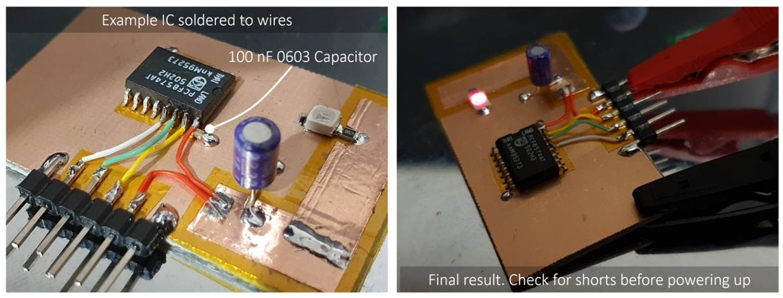
Here's the finished example board. A common scenario is that a 100 nF capacitor is required across the power rails for ICs. The photo below shows how that is achieved.

image

Once I'm happy with the circuit, sometimes I'll use epoxy glue to make some of the larger components or wire leads more secure. The result is more than good enough for prototyping, before ordering a printed circuit board.


That's it! There are plenty of variations that could be tried. Some people mount the ICs upside-down (known as 'dead bug' construction). Sometimes isolated areas are required and a knife can be used to cut the copper and peel it out, and one variation does that using a special drill bit to cut copper disks.


Thanks for reading!

  • Sign in to reply

Top Comments

  • fmilburn
    fmilburn over 4 years ago +8
    Hi Shabaz, Very nice. While not directly related, I would think some of these techniques would be good for repairing goofs with wire on PCBs as well.
  • genebren
    genebren over 4 years ago +7
    These are some great tips and tricks. You have a very good hand and a super helping of patiences to do some of this very detailed work (which not all of us have). I am so impressed with the overall quality…
  • geralds
    geralds over 4 years ago +7
    Oh yeah, shabaz Fantastic memories coming up! Namely, I built my FIRST circuit board with a piece of cardboard and glued the foils of an electrolytic capacitor on it by cutting out this unwound foil and…
  • shabaz
    shabaz over 4 years ago in reply to kmikemoo

    Hi Mike thanks! I don't enjoy cutting into the copper since the tools for that are in the outside cold shed : ) so copper tape is preferred for that reason too!

    • Cancel
    • Vote Up +5 Vote Down
    • Sign in to reply
    • More
    • Cancel
  • gordonmx
    gordonmx over 4 years ago

    I have work with Cu tape before.  One of the most important things to have on hand is bandaids.  8^)


    Stay Safe & Well,


    Gordon

    • Cancel
    • Vote Up +5 Vote Down
    • Sign in to reply
    • More
    • Cancel
  • DAB
    DAB over 4 years ago

    Great post.


    Some of my  earliest circuits were done on cardboard with aluminum foil cut for traces.


    It worked surprisingly well.


    DAB

    • Cancel
    • Vote Up +6 Vote Down
    • Sign in to reply
    • More
    • Cancel
  • neilk
    neilk over 4 years ago

    shabaz, that's fantastic. I would never have thought of that approach in a million years!


    Thanks so much for posting.


    Neil

    • Cancel
    • Vote Up +5 Vote Down
    • Sign in to reply
    • More
    • Cancel
  • navadeepganeshu
    navadeepganeshu over 4 years ago

    A good collection of SMD to DIP adaptors out there image

    image

    -- Art of Electronics Pg 65


    Oh, painful, painful insult,.......It sometimes feels like going back and getting DIP variant of the same component. Its always very handy!

    • Cancel
    • Vote Up +5 Vote Down
    • Sign in to reply
    • More
    • Cancel
>
element14 Community

element14 is the first online community specifically for engineers. Connect with your peers and get expert answers to your questions.

  • Members
  • Learn
  • Technologies
  • Challenges & Projects
  • Products
  • Store
  • About Us
  • Feedback & Support
  • FAQs
  • Terms of Use
  • Privacy Policy
  • Legal and Copyright Notices
  • Sitemap
  • Cookies

An Avnet Company © 2025 Premier Farnell Limited. All Rights Reserved.

Premier Farnell Ltd, registered in England and Wales (no 00876412), registered office: Farnell House, Forge Lane, Leeds LS12 2NE.

ICP 备案号 10220084.

Follow element14

  • X
  • Facebook
  • linkedin
  • YouTube