


After creating baseband IQ data, the next step in my test setup was to take these signals into a IQ modulator, which was supposed to produce RF modulated QAM signal in band between 20-65 MHz, in compliance with DOCSIS 2.0/3.0 standard, used in cable TV systems return path (upstream) for two way communication link and Internet access.
However, Murphy got me and I discovered that the modulator does not work anymore. What to do now?
I immediately thought of more than adequate 120 MHz of analog bandwidth of 33622A and 1 GS/s of sampling rate.
I am well aware that this is not "approved usage" of this unit, but being curious I wanted to to push this thing to its limits.
So, how do you create complex digital RF waveform?
One solution is to use Matlab, create the digital data and export it to the generator. Since my Matlab skills are not great, this was no option for me.
Another solution is to use dedicated software that big manufacturers have in their lineup, and which is perfectly suited for this kind of application.
Agilent's Benchlink Waveform software does not even comes close to creating something like this. Agilent has Signal Studio software which is big and expensive, intended for their top of the line X-series RF signal generators. Needles to say it does not work with 33600A series of generators, at least not reasonably straight forward.
Agilent probably is not very interested in enabling such features on 33600A series, since it probably could eat up in their top of the line range sales.
Scouring the web I came across the very nice and small piece of software that promissed to do exactly what I needed. It is called ArbIQ, developed by the very man who wrote excellent paper "Complex modulation generation with low cost arbitrary waveform generators", Mr. Joan Mercade from company "Arbitrary resources" in Spain. There is a trial version available for download, however it is limited and unable to transfer waveform to generator or to save it. If you want to try it, here is the link: Arbitrary Resources, S.L.
I contacted Mr. Mercade via email and asked him if he would be willing to make 2 files for me using his software, both using 64 QAM modulation, with 2 and 4 carriers, and with PRBS payload data. I was very pleasantly suprised when the email came few day later with generated files and detailed explanation.
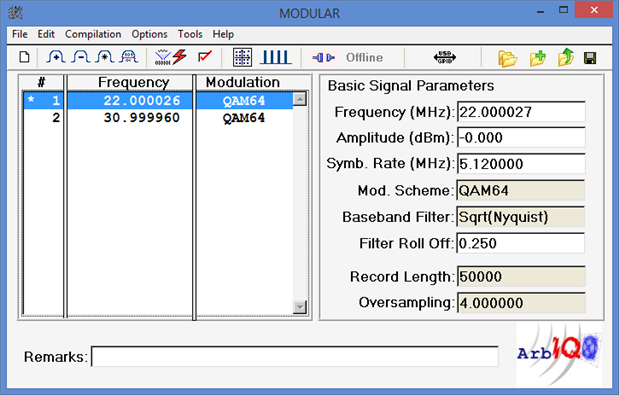
So here is what I got, this is the first file with 2 carriers, at 22 and 31 MHz, 5120 ksym/s symbol rate, alpha factor of 0.25 and raised cosine (Nyguist) filter applied.
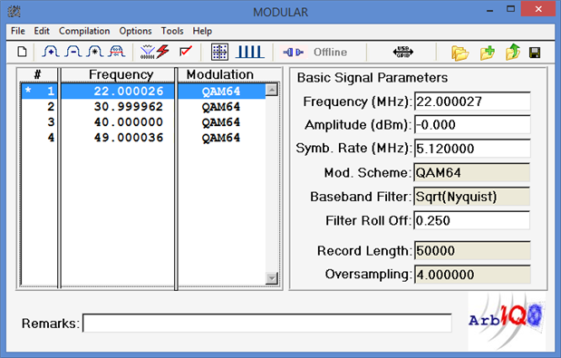
And also the 4 carrier version, 22-31-40-49 MHz, all other parameters the same.

Mr. Mercade also provided detailed description of the generated signals:
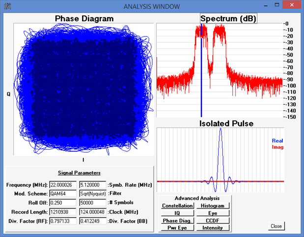
"Each signal have different sampling rate (the Clock parameter) and record length, although they carry the same number of symbols, 50,000. Waveforms are compiled in such a way that there should not be any wrap-around issue and the symbol rate is kept. In order to fulfil these requirements and keep the number of samples as an integer, the carrier frequencies have been slightly adjusted within a few Hz.
This error could be reduced by carefully selecting the record length parameter or just by calculating a signal with more symbols in it, but I think that the error is quite acceptable (and predictable).
The constellation you see is for one carrier and before applying the matched filter at the receiver, so it looks noisy because of the intersymbolic interference produced by the sqrt(raised cosine) filter as required by the DVB-C standard. Modulation quality should be perfect, though, after applying the signal to a DVB compliant receiver.
All the carriers use the same data sequence (PRBS) but I have chosen to incrementally delay the data for each carrier. The phase of the carriers itself has been randomized to avoid that all the signals reach their peak at the same moment in time. The overall Crest Factor is reduced and the signal behaves more realistically while the power and linearity are optimized. "
Once again, I would like to publicly thank Mr. Mercade for his immense help 
After some conversion and normalization of signals in the Benchlink software, I loaded them into 33622A and took the output into the Promax Explorer HD advanced SAT&TV analyzer, commonly used by technicians and engineers dealing with CATV HFC networks.

And the 4 carrier version:

Power readings are slightly off due to the fact the instrument has fixed 0.15 alpha coefficient for DVB-C signals which would correspond to 5.88 MHz of bandwidth for 5120 ksym/s SR, but with alpha of 0.25 bandwidth is actually 6.4 MHz... Since I don't have the ArbIQ software to change the signals, I left it as it is. In the words of British car workers from the 80's "that'l do".
Generated signals have pretty good C/N ratio of 40-45 dB. This is not up to par with the dedicated RF signal generator, but I think that this is very good result and speaks a lot about the low jitter claims and overall signal integrity of Trueform technology. For reasons unknown to me at this time, Promax Explorer HD refused to make MER measurements. BER measurements are not available since packets are not properly formed in the first place.

QAM constellation diagram after demodulation shows good results, tightly packed symbols, and no phase balance issues.

Not bad for entry level (on Agilent's scale) arbitrary signal generator...