


Background
I have a Siglent SDS2000X HD series oscilloscope, which has a built-in logic analyzer but requires a separate SPL2016 probe. I mainly use an Analog Discovery 3 as my logic analyzer, but the oscilloscope offers deeper memory per channel and a higher sampling rate, which could be beneficial in certain scenarios. I came across a user, OZ2CPU, who designed a DIY version of this probe. You can find more information about the project here: https://www.thingiverse.com/thing:4784443. There is also a dedicated discussion thread on the EEVblog forum. I have decided to build my own version based on this project.
The DIY kit
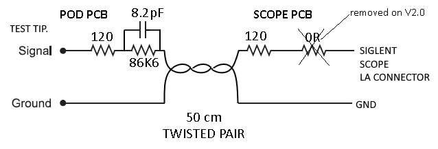
The probe is completely passive and consists of a few components mounted on both the scope-side and pod-side connectors. I contacted a user who had already built the same probe and still had some spare PCBs and 3D-printed enclosures. He kindly offered to sell me these spare parts. I received an almost complete kit, with the resistors already soldered onto one side of the PCBs. The only components I needed to solder were the stacked 8.2 pF capacitors on top of the 86.6 kΩ resistors on both pod PCBs, and the 120 Ω resistors on the scope-side connector. The original project assumes the use of twisted pairs from DVI or HDMI cables. However, I decided to use flat, thin Ethernet cables for this purpose instead. Here is a photo of the kit, ready for assembly: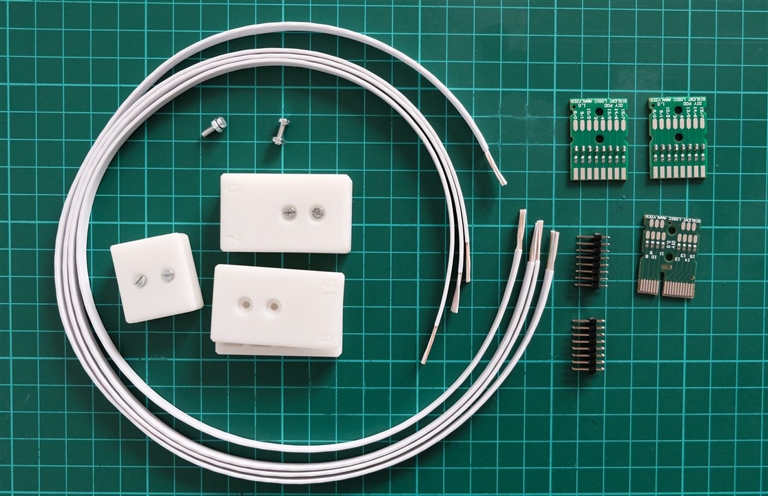
The assembly process
I started by soldering the sixteen 8.2 pF capacitors on top of the 86.6 kΩ resistors on both pod PCBs.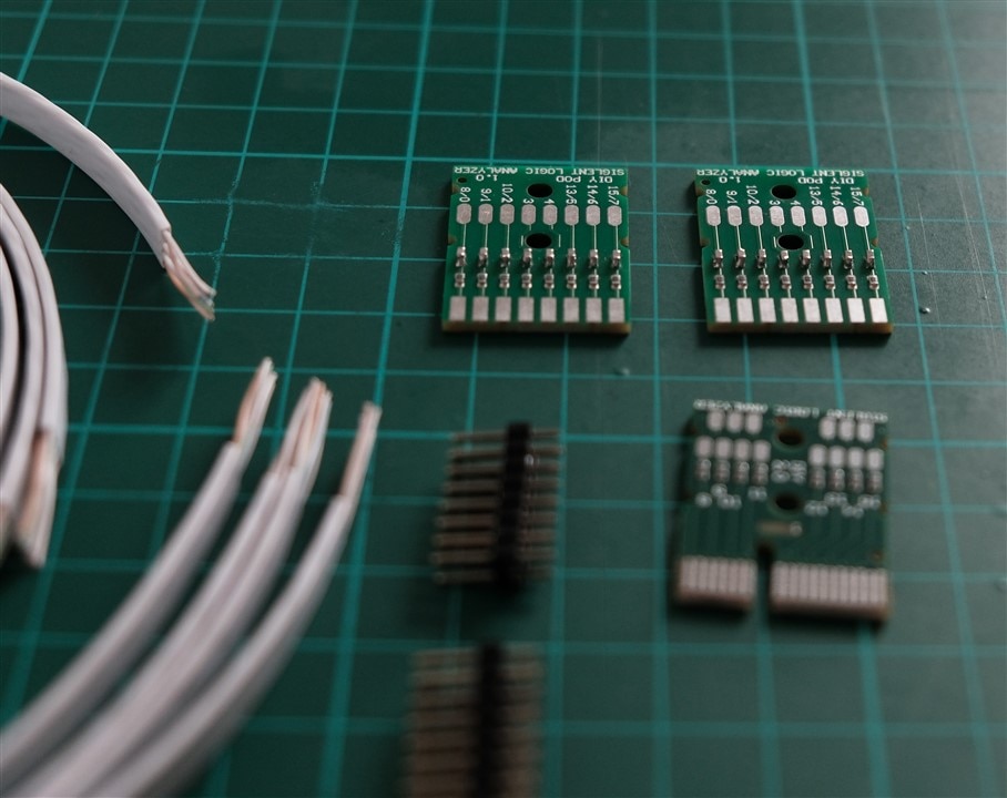
After that, I soldered the remaining eight 120 Ω resistors onto the scope-side connector.
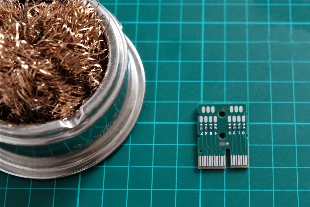
Next, I soldered the pin headers onto the pod PCBs.
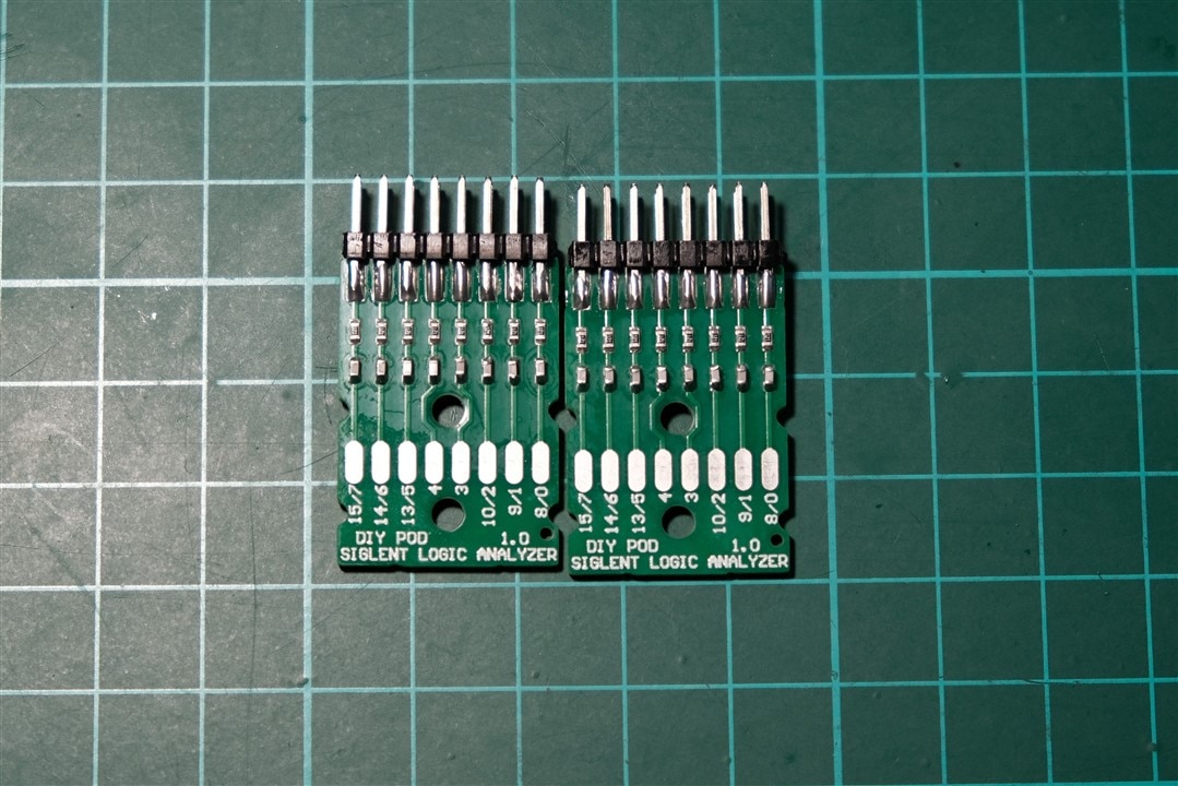
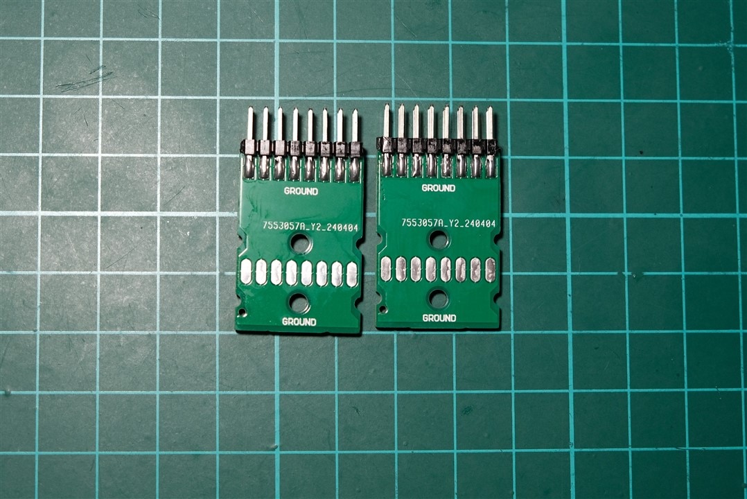
After that, I prepared the wires and soldered them to the pod PCBs.
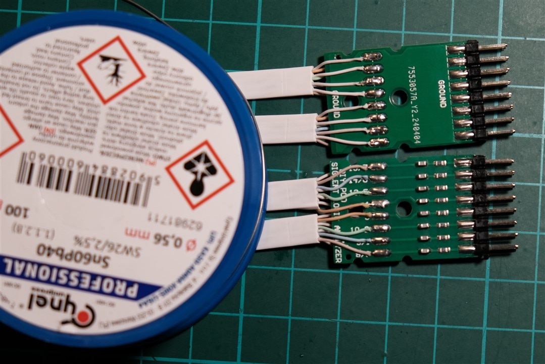
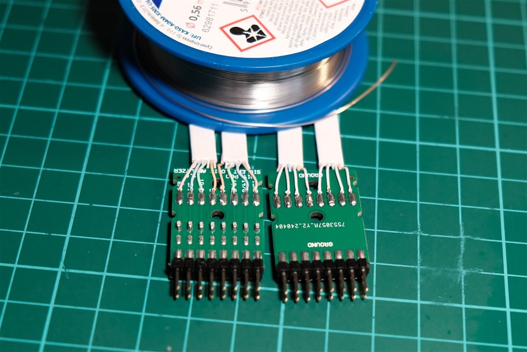
Next, I soldered the wires to the scope-side connector PCB, making sure to follow the correct order.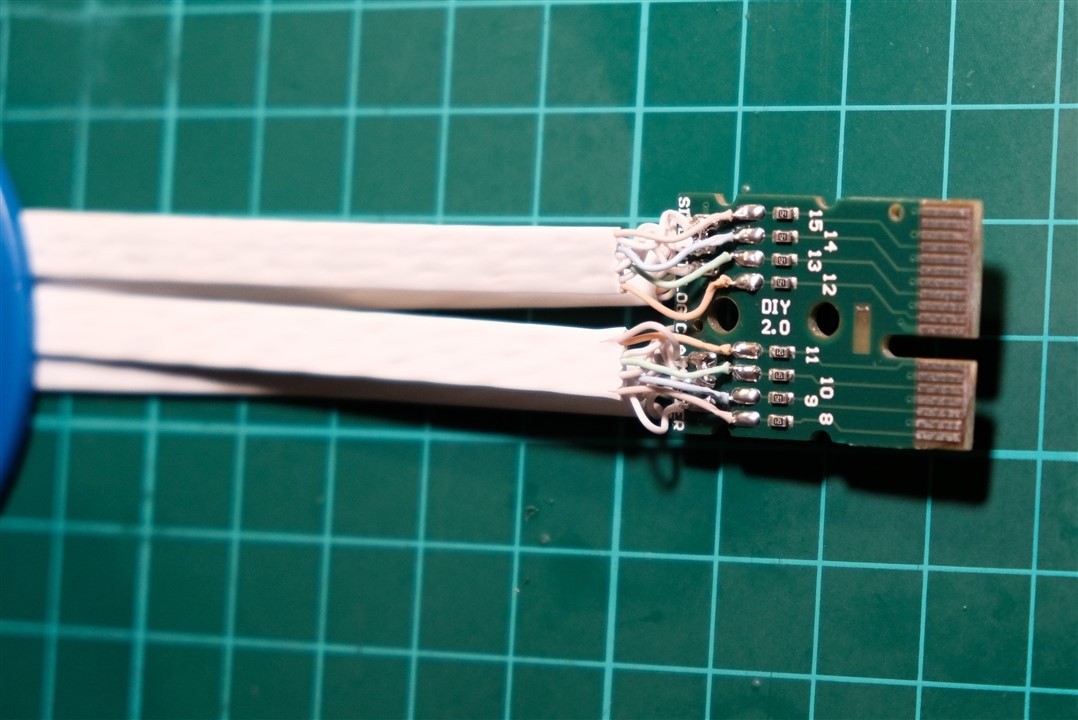
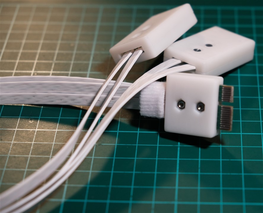
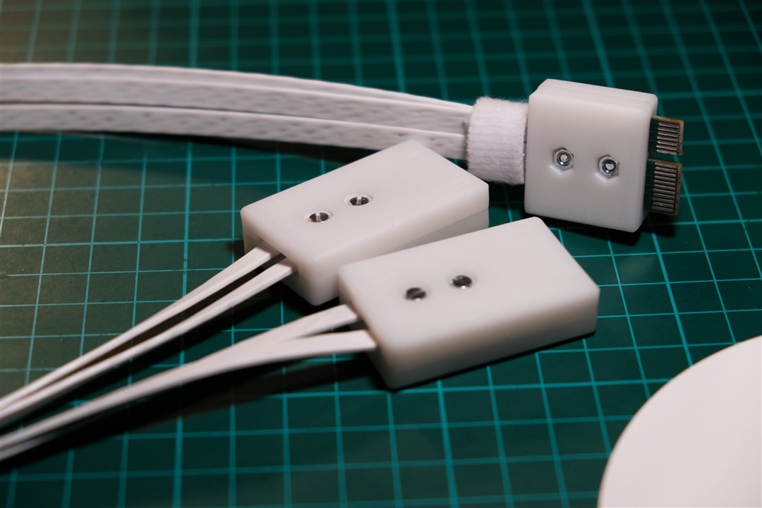
After checking the connections on all sixteen lines, I installed all the PCBs into their 3D-printed enclosures. Here is a photo of the fully assembled logic probe.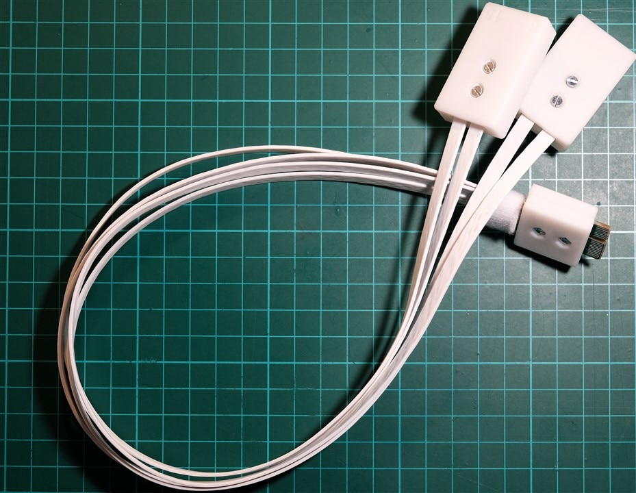
Testing with oscilloscope
After assembly, I connected the probe to the oscilloscope and performed an initial test using the oscilloscope's built-in 1 kHz square-wave calibration signal. All sixteen channels worked properly. Here are some screenshots captured during the test.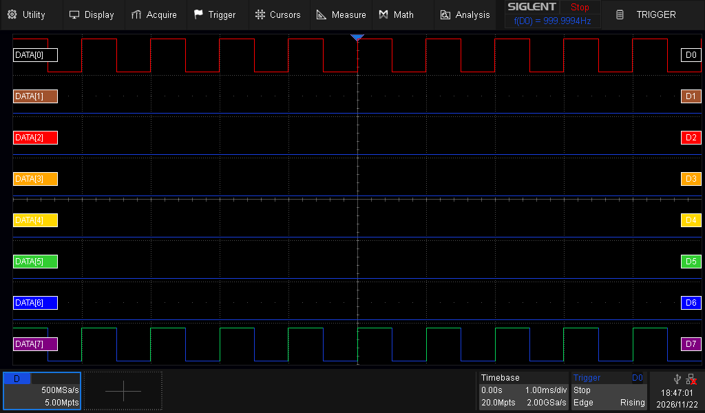
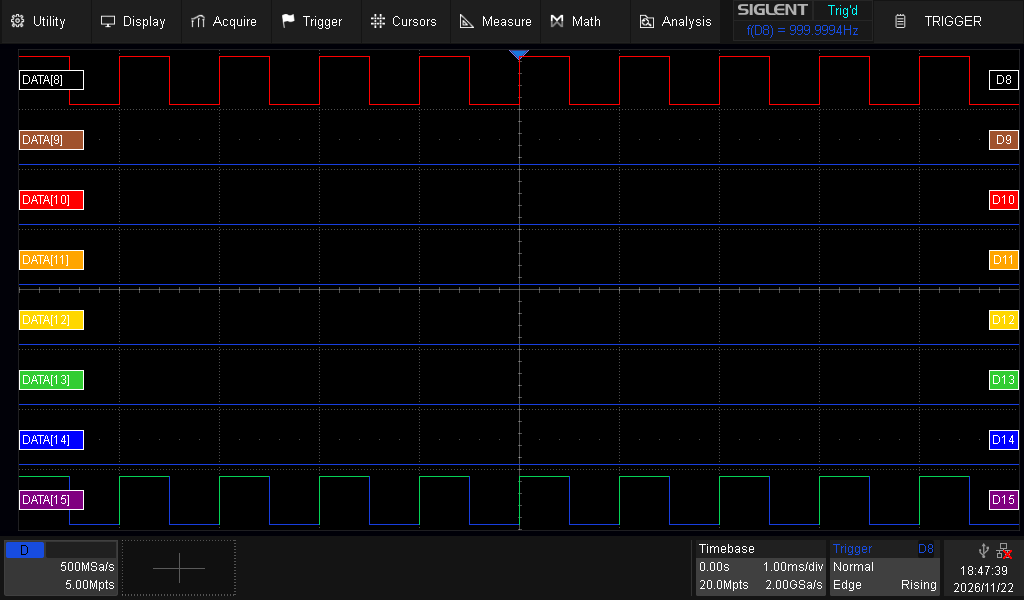
I will also perform further tests later using faster signals, approaching the bandwidth limits of the original probes, to see how well this DIY version performs. However, the initial results look promising: this DIY version works well and is relatively easy to build yourself.