


Table of Contents
Introduction
Have you ever wanted to take a peek at what products that rely on light are actually doing? I have! A fast-responding light sensor can reveal the details.
To sense light, ordinarily, I’d consider a photoresistor or, if I needed a faster response, a phototransistor or a photodiode. However, I recently needed a way to sense light pulsing at a far higher rate than normally expected; let’s aim for 20 million times a second! (There is also a version of this project that has nanosecond-level response; see further below, and in the comments, for detail on that).

I browsed the Farnell website and found a very neat silicon PIN photodiode from Hamamatsu that has a response that can reach 30 MHz.
This blog post describes how the photodiode can be built into a very simple circuit that provides an output of the amount of power hitting the sensor, and it’s usable for measuring UV-A, visible light, and it operates through to near-infra-red (320 to 1100 nm wavelength).

Note that the particular photodiode that was used is quite pricey at approximately £13+ tax, but you could use a far cheaper ($1) photodiode if you don’t need such a high frequency response.
Circuit Overview
The circuit is straightforward. It uses a photodiode, and a few passive components. If you want to replicate, then C1 is an 0603 sized 10 nF 50V C0G capacitor, and C2 is a 10uF 20V tantalum capacitor. R1 is an 0603 or 0402 sized 100 ohm resistor. The diode D1 is model S1223, but you could replace with a cheaper SFH 203 part if lower bandwidth is acceptable.
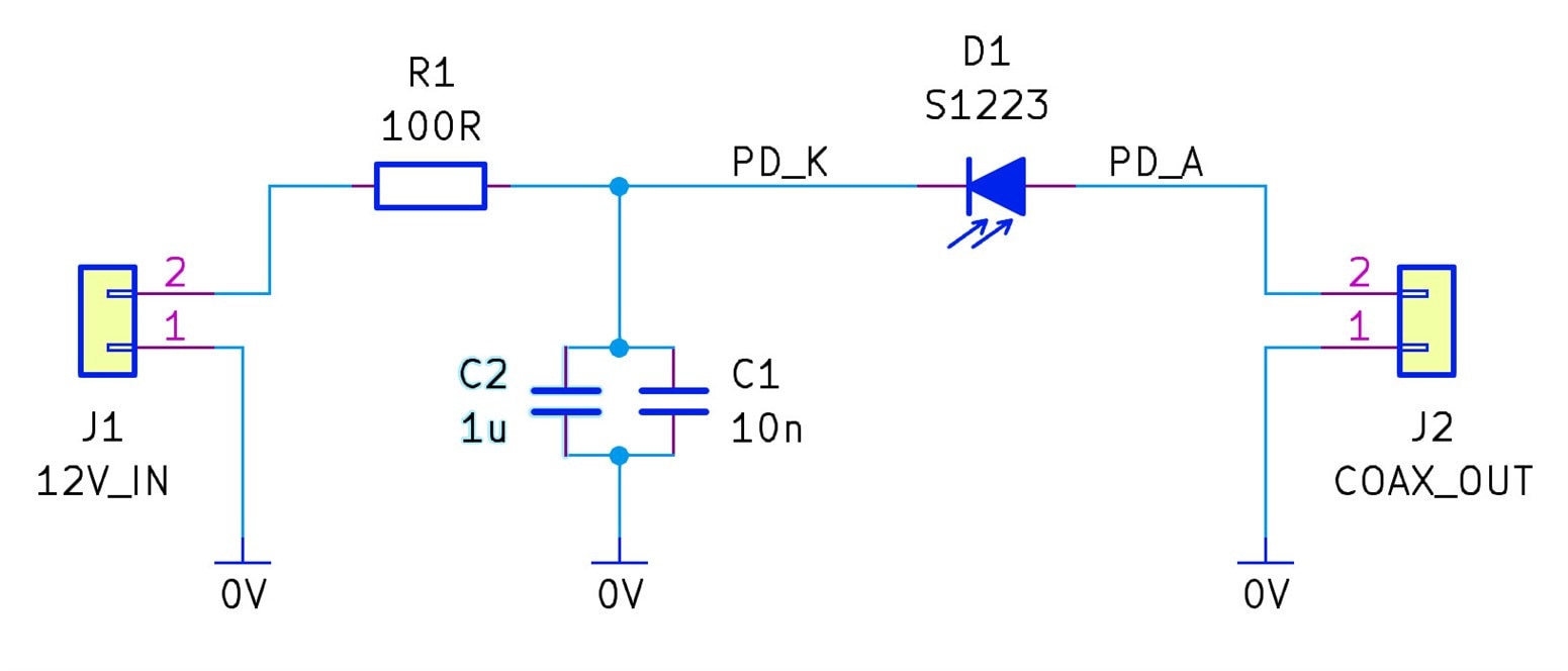
A reverse bias voltage is applied to the photodiode, so that the photodiode’s capacitance is reduced significantly, so that it can be used at high frequencies. The photodiode will produce a current that is dependent on the amount of light power hitting the diode. That current is converted to a voltage for measurement, by passing it through a resistance. Other than that, there’s a bit of bias voltage filtering, and some care to shield everything since the current (and voltage) will be very low. An amplifier is outside the scope of this blog post, but you could use a multimeter to see the measurement (if the light level is not changing). For observing fast-changing light levels, the output can be connected to an oscilloscope.
I picked 12V of reverse bias; it’s a compromise, because a high value reduces the capacitance of the photodiode, but it also increases the dark current through the diode. 12V is a convenient voltage to obtain from batteries, so that was a factor to consider too!
At 12V, the capacitance will be about 16 pF (according to a chart in the S1223 PDF datasheet). The bandwidth limit is determined by 1/ (2 x pi x Rload x 16pF), which indicates that the bandwidth will reach the datasheet specification of 30 MHz, provided the load resistance is less than about 300 ohm.
I assumed a maximum current of 10 mA through the diode (according to the chart, this would occur for 16 mW of power hitting the sensor at 980 nm, or 22 mW of power at 660 nm). That’s an extreme amount of light power to be concentrated in such a small area, it is more than I’d ever expect to use the sensor for (to put it in perspective, under normal room lighting, the sensor will likely be exposed to about 4 micro-watts of light power hitting it).
Using the formula in an OSI Optoelectronics PDF application note, this means that the resistor in the filter circuit needs to be less than 12V / 10 * 10mA, which is 120 ohm; I used a 100 ohm resistor.
The value of the capacitor needs to be as large as practical, and greater than (10 x t)/50 ohm where t is the pulse width, and where it’s assumed that the coax cable will be terminated with a 50 ohm resistor. I decided to use a 10uF tantalum capacitor, plus an 0603-sized 10nF NP0/C0G ceramic capacitor. Unfortunately once it came to construction time I realized I didn’t have a 10uF 20V tantalum capacitor that would fit : ( so I used a 1uF capacitor.
Building It
This project uses a cheap extruded aluminium enclosure (the AliExpess search term for it is project enclosure 80x25x25mm), barely bigger than the AA-sized battery connector that it will house. The end panels can be discarded. The ends of both extrusions need to be sanded, so that shiny bare aluminium is exposed (this is so that it can mate with the replacement end panels about to be discussed next).

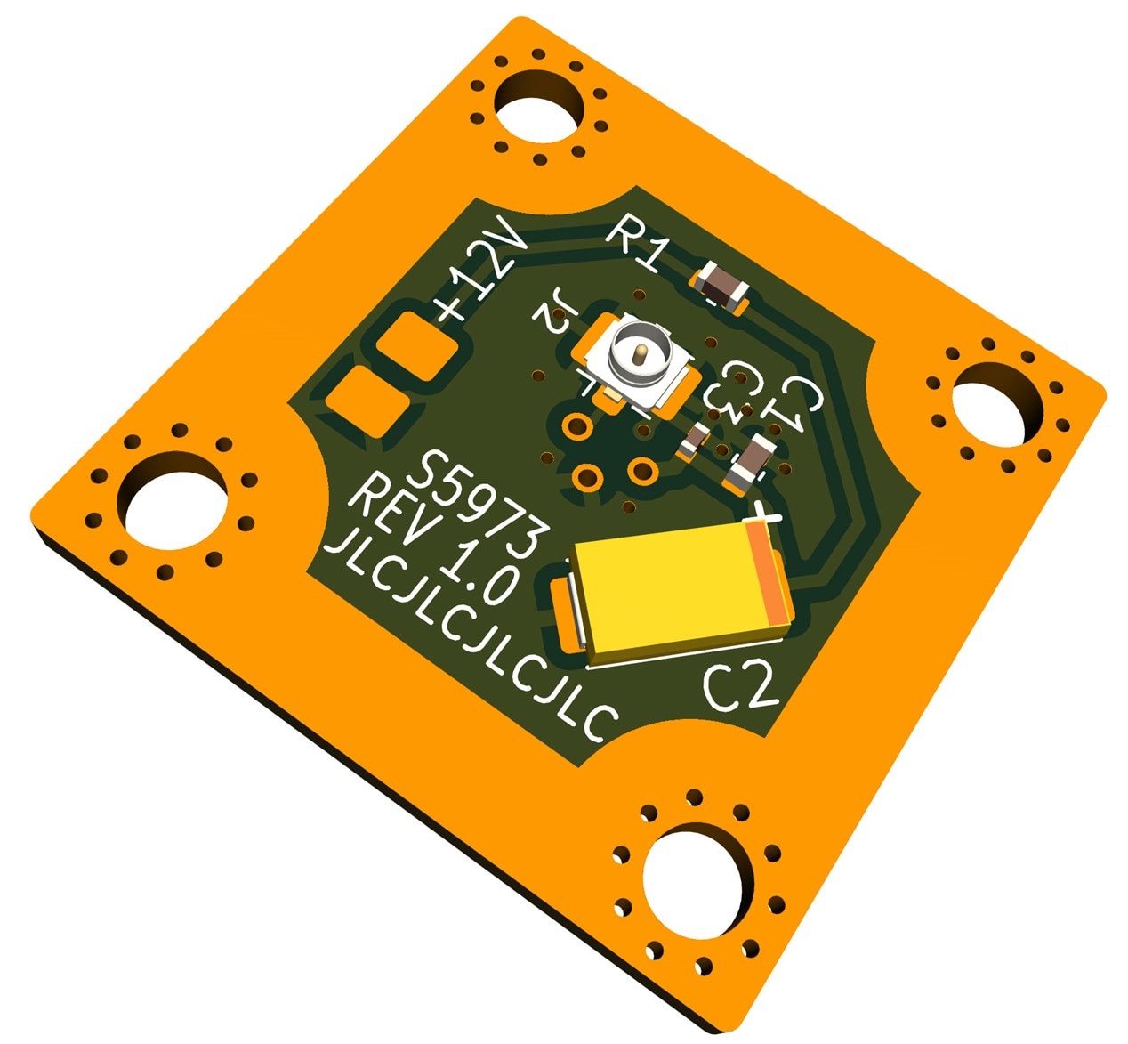
To simplify construction, I decided to create a little printed circuit board (PCB) for the project. It replaces the side panel on the aluminium enclosure. Refer to the PCB render below to see where to solder all the parts. It’s very easy to assemble (with a small soldering iron tip, and tweezers to hold the three surface-mount parts).
After that, I soldered a twisted wire pair to the connections labelled OUT, and soldered a single AA battery holder to the 12V connections, and then applied some glue to prevent the wires breaking off.
The photodiode was inserted from the other side and soldered too.

For the other end panel, I created another small PCB, this time with no components, just an SMA connector hole. This is a bit lazy; I could have drilled a hole in the enclosure! PCBs are cheap, though.

I got lucky and discovered that although the enclosure is not designed for it, the AA battery holder can be slid into the enclosure, and it is held firmly. It takes a bit of force to wedge it in. If it doesn’t wedge in, then it could just be glued in place.
The AA battery holder was convenient, because then two 1/2-AA sized 6V batteries (known as 4LR44 batteries) can be fitted, for the 12 V supply that the circuit needs.
I didn’t bother with a power switch. Hopefully, in normal use, the batteries should last at least a year or two.
The other end panel contains the coax connector (I used an SMA connector), and the OUT wires need to be soldered to it.
All the electronics should now be complete! This project took about an hour to assemble from start to finish.

I drew a label to glue onto the device. The chart provides the information needed to work out how much light power is reaching the sensor (and, therefore, what the output voltage will be, across a 50 ohm termination, using Ohm’s Law), provided that the light wavelength is known.
If you wish to build the project with the same photodiode, then the chart is displayed below, so that it can be made into a label as desired.

Using It
The output can be connected directly to an oscilloscope using a SMA-to-BNC cable. The ‘scope should be set to 50-ohm input termination, and if the ‘scope does not support that, then that’s no problem at all; a BNC T-piece can be used at the ‘scope end, with a 50-ohm BNC terminator twisted on.
The photo below shows the output when a TV remote control button was pressed. The remote was placed a few inches away from the sensor. You can see the ‘pulses’ that assemble into the control protocol.

It’s possible to adjust the ‘scope timebase setting, and zoom in further; now it can be seen that the light is pulsing 40,000 times a second:

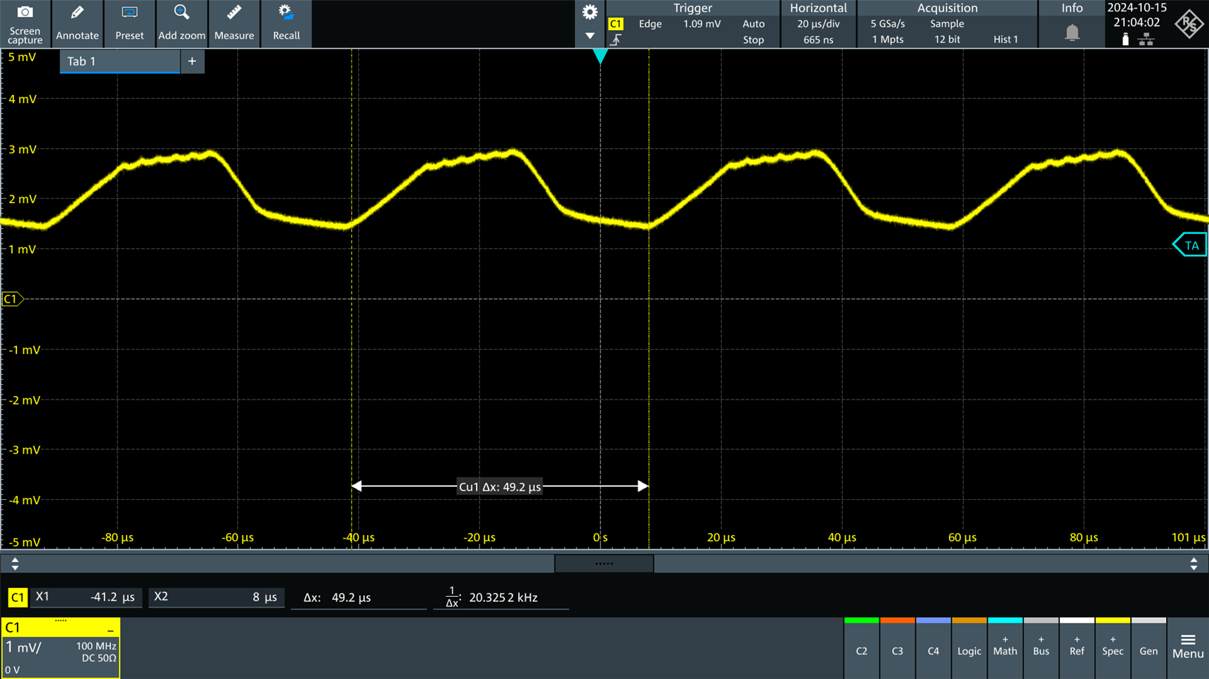
I shone my camera light toward the sensor, and observed that the light has ripple at about 20 kHz. From the ‘scope trace below you can see that the light energy doesn’t reduce to zero; I’m guessing the phosphor covering each LED continues to glow in-between each pulse.
Next I shone a flashlight at it. The frequency of operation was far higher, at 324 kHz.

The photo below shows a far higher light output pulse rate; 17.8 million times a second! This is from a laser firing rapidly.

Even Faster Responding! S5973 Version
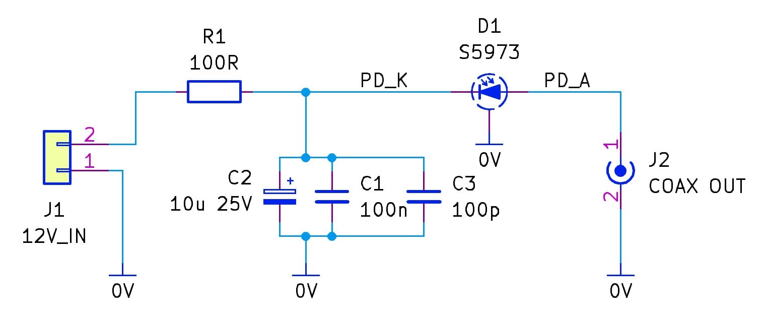
In the comments below, someone asked for nanosecond-level response capability. There's a S5973 diode from Hamamatsu, which is suitable for that! It uses a different PCB:
The main difference is now some more care is needed with the capacitor placement (and a 0402 capacitor is also required), and a short (100mm) U.FL to SMA cable is used to attach the output from the front PCB to the rear PCB.
This is the circuit diagram:
Parts List:
Ref  Value          Description                   Farnell Code
C1   100n           Cap X7R 0603                  3013413
C2   10u 25V        Cap 10u 25V TPSC106K025R0500  570450
C3   100p           Cap 0402                      1414603
D1   S5973          Photodiode Hamamatsu          1495575
J2   U.FL-R-SMT(01) Hirose U.FL Connector         3908021
R1   100R           Res 0603                      9238360
n/a  U.FL Cable     U.FL to SMA 100mm MC000812    2452708
n/a  Batt Holder    AA Holder MP000328            3126564
n/a  6V Batt x 2    4LR44 (6V) Batteries (2 required)
n/a  SMA/BNC Cable  SMA to BNC cable to connect to Oscilloscope
Summary
A photodiode was connected in a simple circuit, which allows the user to see how much light power is arriving into the sensor. It’s very easy to assemble, with just an hour or two of work. The PCB Gerber files are available on GitHub. There are actually three files there; one is suitable for lower-cost 5mm-diameter photodiodes; the rest of the circuit can remain the same unless you wish to experiment with any values.
I think there’s lots to learn about the secrets of products that rely on generating light, so this sensor project will hopefully find many uses.
Thanks for reading!

