


Note: Also check out the ADALM1000 being used to monitor current consumption of a CodeBug.
Introduction
The Analog Devices (AD) Active Learning Module ADALM1000Active Learning Module ADALM1000 is a nice compact board (near credit-card-sized) that is designed to help in electronics education. It can also make a great low-cost test tool.

It has a lot of functionality – it is like a Swiss army knife for electronics. It behaves like a low-cost Source/Measure Unit (SMU) which is a tool that is highly interesting for those interested in physics, understanding semiconductors, and gaining deep knowledge about how a circuit behaves.

The photo above shows it powered up; the photo below shows what comes with it.

The ADALM1000ADALM1000 is extremely new (was available at Farnell only yesterday) so while the software is excellent, it does need a few small improvements. fortunately, it is all open-source. Improvements will occur over time. For further information also see the ADALM1000 Design Center Home.
What does it do?
In operation, it behaves like a dual power supply where either (or both channels) can be set to a constant voltage (like usual power supplies) or a constant current. So one could set a channel to 3.3V for example, or 5V, and power circuits with it. Alternatively, a channel could be set to (say) 10mA in constant current mode and used to power up an LED (or perhaps a couple of LEDs in series without requiring a series resistor). Very much different from a normal power supply, the ADALM1000ADALM1000 can also be programmed to generate patterns such as a sine wave or sawtooth if a constant supply is not desired.
The power supply functionality is one-half of the SMU capability (it is the ‘Source' part of the SMU acronym). The other half is the ability to measure. While the circuit is being powered it is possible to use the tool to simultaneously measure the current or voltage. For example, if a circuit is being powered by 3.3V from the ADALM1000ADALM1000 then the device will also report current consumption of the circuit under test. In a similar manner if an LED is being supplied with a constant current of 10mA then the ADALM1000ADALM1000 will report the voltage that is across the LED.
The voltage and current sources can be switched off if desired and the channels can be used as simple voltmeters with graphic trace capability. This extends the usefulness of the ADALM1000ADALM1000 even further.
The reporting is done in real-time at up to 250 K samples per second; this allows for an oscilloscope-like display. The high speed is great for (say) testing a radio transmitter where the transmission burst lasts just tens of milliseconds; whenever it transmits it would be possible to see the increased current consumption on the graphical display (but see bug list below).
The SMU can also be used like a ‘curve tracer’ which is an instrument that can slowly vary current or voltage over time in order to produce a curve showing basic electrical characteristics of an electronic component.
Real SMUs and curve tracers are designed to operate over many orders of magnitude (decades) of voltage and current and therefore are quite advanced instruments. The ADALM1000ADALM1000 is an extremely low cost tool and can only provide a taste of what a real SMU can do. The ADALM1000ADALM1000 uses 16-bit analog to digital and digital to analog conversions (ADC and DAC) and has voltage and current limits of 0-5V and 0-200mA respectively and is powered from a PC or laptop using a USB cable.
SMU-like functionality can be useful for other test instruments too; check out Project Morpheus, aka the Battery Simulator project which is being worked on.
This is the underside view:

The photo below shows some of the main functional areas of the ADALM1000ADALM1000 board:

Building the Software
(Note [October 2015]: A windows executable/installer is now available if you prefer that path. Check out the comments to the post, they explain the windows installation detail).
As a first step, download Ubuntu.
If you’re not using Linux, install Virtualbox or Fusion on your Windows/MAC machine as appropriate (it should be possible to build the code for these platforms but sometimes it is easier to just drop a Linux VM into your PC).
Set the VM network connection to ‘Bridged’. Once Ubuntu is installed and running, open up a terminal. Enable the root user password:
sudo su
passwd
As root user:
apt-get update
apt-get install git
Start up Ubuntu Software Center, and in the search bar, type libusb-1
Select libusb-1.0-0-dev and install it (when installed, there is a small green circle with a check-mark against the icon).
Search and install g++ using the same method.
Exit out of root user, and type the following command; it may take a few minutes, it is a >500MB file:
wget http://qtmirror.ics.com/pub/qtproject/development_releases/qt/5.4/5.4.0-rc/qt-opensource-linux-x64-5.4.0-rc.run
chmod 755 qt-o*
./qt-opensource-linux-x64-5.4.0-rc.run
Accept all the defaults and install Qt5.4 (it takes about 30 seconds). Don’t bother launching Qt Creator after it installs.
Back in the Software Center, type qtdeclarative5-con in the search bar, and install the qtdeclarative5-controls-plugin
Also, search for qtdeclarative5-qu and install the qtdeclarative5-quicklayouts-plugin if it is not already installed
Repeat for qtdeclarative5-dev
Now type:
su
cd /usr/lib/x86_64-linux-gnu/qt-default/qtchooser
ls -l
rm default.conf
ln -s ../../../../share/qtchooser/qt5-x86_64-linux-gnu.conf default.conf
ls –l
exit
Next, from the home folder, not as root user, type:
mkdir development
cd development
git clone --recursive https://github.com/signalspec/pixelpulse2
cd pixelpulse2
mkdir build
cd build
qmake ..
make
After a minute or so, the software build is complete.
Running the Software
Plug in the ADALM1000ADALM1000 into a USB port and an LED should light up in a pink/purple color. Confirm that it is visible to your VM by typing:
lsusb
The output should contain a line saying:
Bus 001 Device 002: ID 064b:784c Analog Devices, Inc. (White Mountain DSP)
If you can’t see any Analog Devices entry, then you need to troubleshoot (it is likely to be a setting in Virtualbox/Fusion etc) to allow the guest OS to have access to the USB.
Next, from your ~/development/pixelpulse2/build folder, as root user (i.e. type su first), type:
./pixelpulse2
The output on the terminal will look something like:
Using libusb hotplug
device insert 0x1818b60
If you see an error message or a segmentation fault then you’re probably not running as the root user.
Note that to make use of the current software, a wheeled mouse may be needed (I couldn’t see how to do this using the trackpad on my PC). The screenshot at the top of this post shows where to click or scroll to use the software.
Initial Experiments
Now was the time for fun I just grabbed some components and began pushing them into the connector on the ADALM1000ADALM1000
Resistor
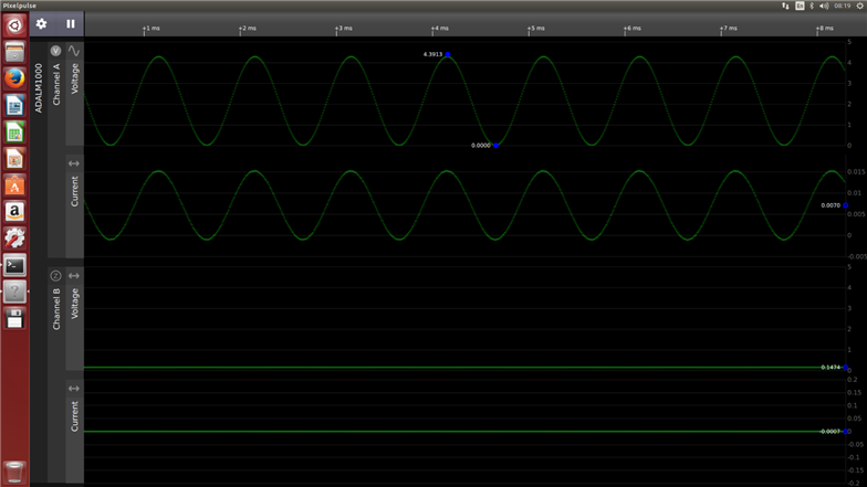
The video here shows a basic experiment; observing the current through a 220-ohm resistor. Note that it can be seen that there is a small negative offset in the current measurement; I have not investigated if the current software allows for calibration; it should be possible to add to the software easily since the source code is available. For this video, channel A was programmed to output a sine wave. It can be seen that the current through the resistor was a sine wave in a similar phase.
The video above is low-res but the actual output can be very high resolution:
1N4148 p-n diode
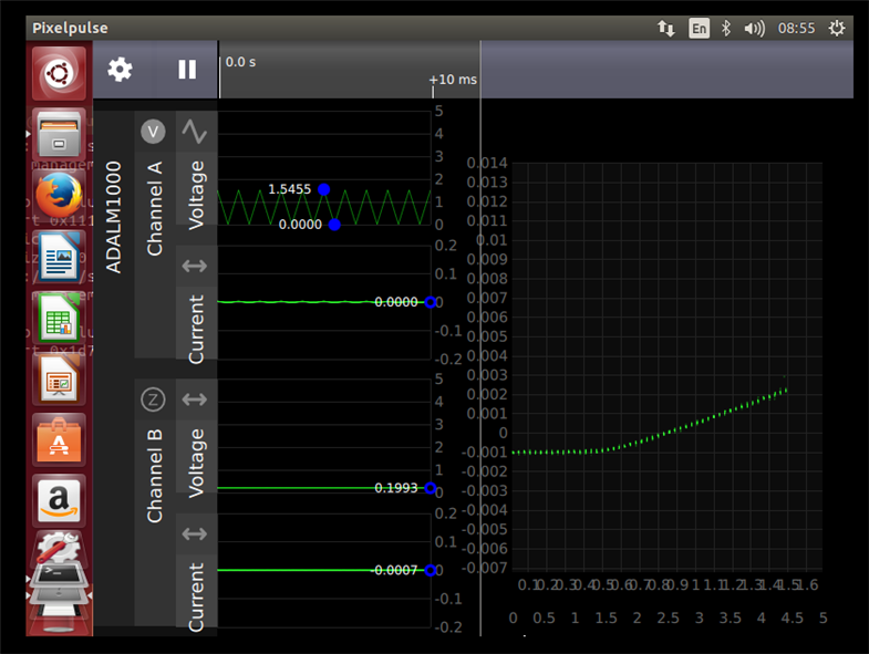
For the next experiment, the resistor was kept and a 1N4148 diode was inserted in series. Plot mode was switched on, which behaves a bit like a curve tracer. The x-axis shows the voltage across the resistor and diode, and the y-axis shows the current through the circuit. The scale appears a little messy (the two lines of text is intended for both channels I believe) but the trace is still very clear to understand. Obviously, changes can be made to the software to improve things if desired.
Tunnel Diode
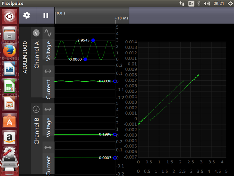
This was the most exotic semiconductor I have. Such diodes have an interesting property that through quantum mechanics the voltage across a tunnel diode can “instantly” snap from one discrete voltage to another (with nothing in-between) as the voltage is increased across the device (the phenomenon is also known as ‘negative resistance’). They are amazing devices. They have some interesting use-cases; for example, they can be used to act as a trigger inside an oscilloscope (and they were used like this at one time; probably not anymore). Tunnel diodes were invented at Sony in the late 1950s by Esaki Leona who was actually trying to improve high-frequency transistor production, and noticed this odd effect whenever he tried to connect wires to his transistor experiment - he then turned the discovery into the tunnel diode and also won a Nobel prize.
The trace below shows the effect; despite seeing it many times it never ceases to amaze me.
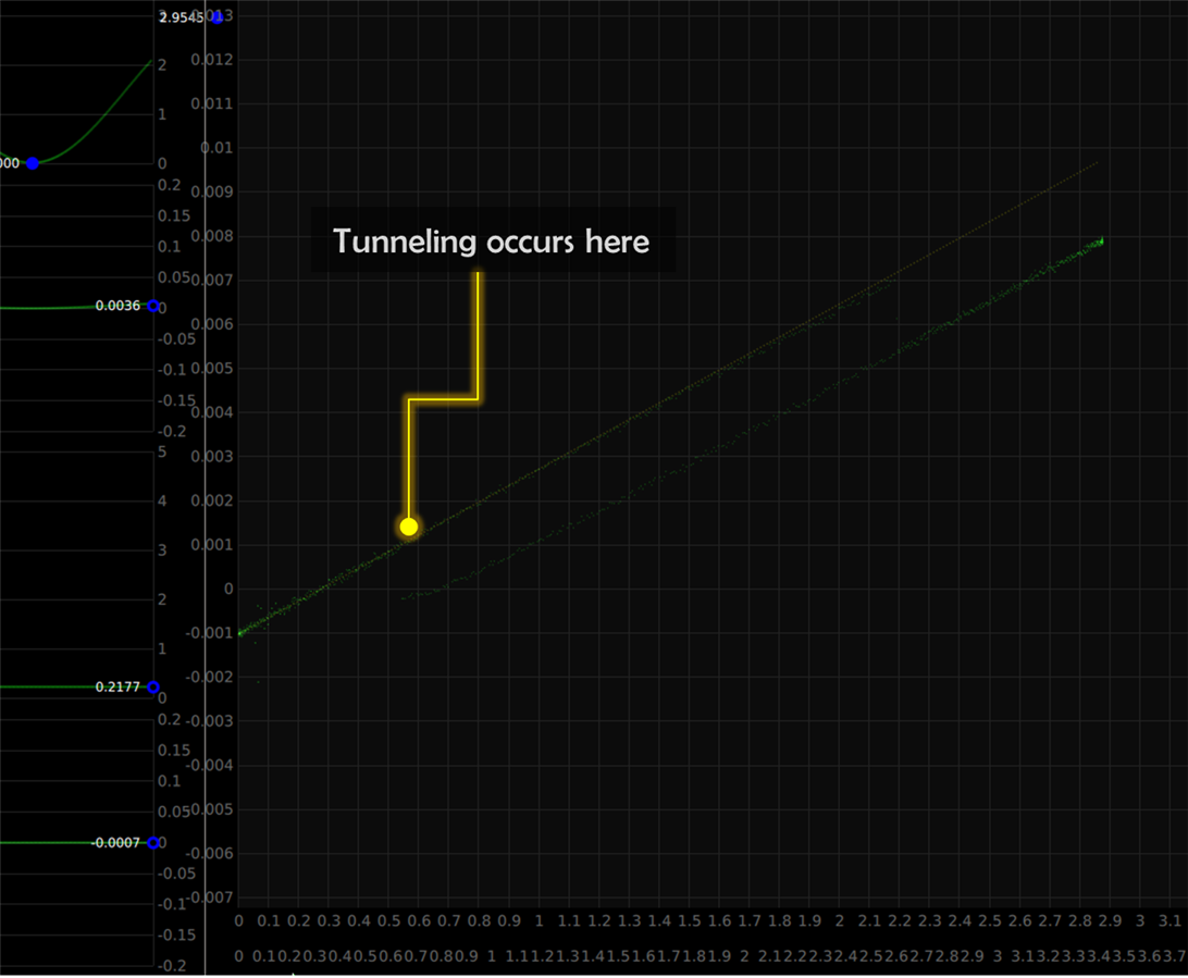
Below it is zoomed-in; the very faint yellow diagonal line that is overlaid shows the trace for just a 220-ohm resistor; the green trace shows the resistor and the tunnel diode in series. It can be seen that as the voltage across the circuit rises, some point came (it happens to be about 55mV across this particular tunnel diode although only the voltage across the resistor and the tunnel diode is observable from the trace) that current no longer rose and instantly dropped across the tunnel diode; this means there was a higher voltage across the diode, a lower voltage across the resistor, and this is visible by the dramatic drop in current at that point. The voltage across the tunnel diode effectively snapped from about 50mV to many hundreds of mV.
It was worth recording a video of the effect:
Summary
The ADALM1000ADALM1000 is extremely good value and provides good insight into components semiconductors and circuits I think it is a game-changer for electronics education but engineers will find uses for it too The application software is extremely promising it is stable(and easy to use and it needs just a few small refinements which will come in time It was straightforward to use the ADALM1000ADALM1000 to run some initial brief experiments with resistors p-n diodes and tunnel diodes
Although this post was a little brief(just a day spent with the ADALM1000ADALM1000 and doesn’t cover much hopefully it is sufficient to get people started with the board I am looking forward to seeing what experimentation people do with it
Bug/Enhancements list
(This is to just record a few things somewhere while the ADALM1000ADALM1000 software is still quite fresh):
| # | Description |
|---|---|
| 1 | Note there is a bug currently in either the firmware or the application software where the output voltage drops to zero(for 100ms or so periodically at a rate depending on the sample time setting This means that the ADALM1000ADALM1000 can currently only be used with semiconductors or very simple circuits It is likely to be a simple fix but I didn’t try to resolve it yet |
| 2 | Selecting items from the cog-shaped menu needs to be done with a single mouse click and then navigate using cursor keys (select by pressing enter or space); it seems to be difficult (or impossible) to do it using the mouse alone |
| 3 | Zooming in time or amplitude requires a wheel mouse; key shortcuts would help too |
| 4 | In Plot mode, the lower x-axis looks a bit weird when zoomed in time: the text sometimes overlaps |
Top Comments