


Table of Contents
Introduction
The DGE1000 series are very compact arbitrary waveform generators! I decided to give one a try. It’s quite low cost (the single channel 30 MHz model, DGE1030, costs just under £70 delivered, if you shop around, with discounts). There’s also a Multicomp branded model, MP751059 which is dual-channel 35 MHz.

What is it?
It’s a signal source. There’s a BNC output, and you can use the keypad and rotary control (or the USB port on the back) to command the instrument to create AC signals so that you can (say) test amplifiers, generate clock signals for digital circuits, sweep a range of frequencies, test radio circuits, and so on. You can precisely control the frequency and amplitude, so that you can test circuits using defined stimulus. Nine times out of ten, most users might just set the instrument to generate sine or square waves, but if desired, you can also generate a variety of other waveforms, and can upload a custom one.
For more detail, see the DGE1000 product and specifications page.
Motivation
Ordinarily a single-channel AWG would be a bad idea, it’s quite limiting not having two channels, however, I already have other signal generators, and I wanted a low-cost AWG that I could attach to equipment that might be faulty or might develop faults; I’d rather accidentally damage a cheap AWG than an expensive one. The 30 MHz frequency range might be limiting too, but I can do a lot with that range regardless.
Note that as with many other arbitrary waveform generators, if you’re not generating sine waves, expect the maximum frequency to be further limited (it’s 15 MHz for square waves for instance, for the 30 MHz and 35 MHz models mentioned here).
Unboxing
It arrived in a small package which I almost didn’t open for a while, because it was so small and lightweight, I thought it contained something boring.
The packaging was totally fine; as well as the AC adapter and cable, you also get a USB cable for PC interfacing, plus a BNC-to-alligator-clip cable in the box.

Since the 5V supply connection is just a normal 5.5mm barrel connector, you could ditch the supplied power supply and use a higher-quality 5V supply if desired. The AWG BNC output shield is connected to the supply 0V connection.
A printed mini user guide is supplied with the instrument.

The DC barrel socket, and USB socket for the PC connection (used for both the arbitrary waveform creation software, and for the USBTMC connection for remote control; it’s configurable) are on the rear. There is no socket for a USB memory stick, so you have to connect to a PC to transfer data to the instrument.

All controls feel fine, the screen is not touch-enabled. You need to hold the back of the instrument when you press a button, to prevent the enclosure from sliding. It’s very lightweight.

Sine Wave Output
I connected the instrument into the spectrum analyzer, and examined a few spot frequencies.
1.4 MHz Signal
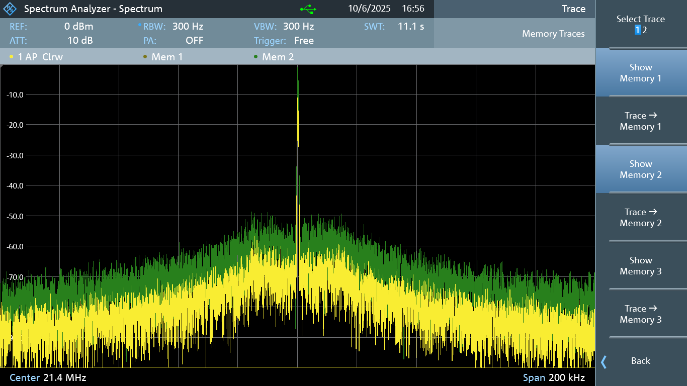
The screenshot below shows the output when configured to 632 mVp-p (about 0 dBm), and 200 mVp-p (i.e. -10 dBm). The span is 200 kHz. There’s no averaging enabled on the spectrum analyzer, so you’re seeing actual output. The output is clean, I have no complaints. It is expected for there to be some raising of the noise level surrounding the signal, and it’s not excessive.

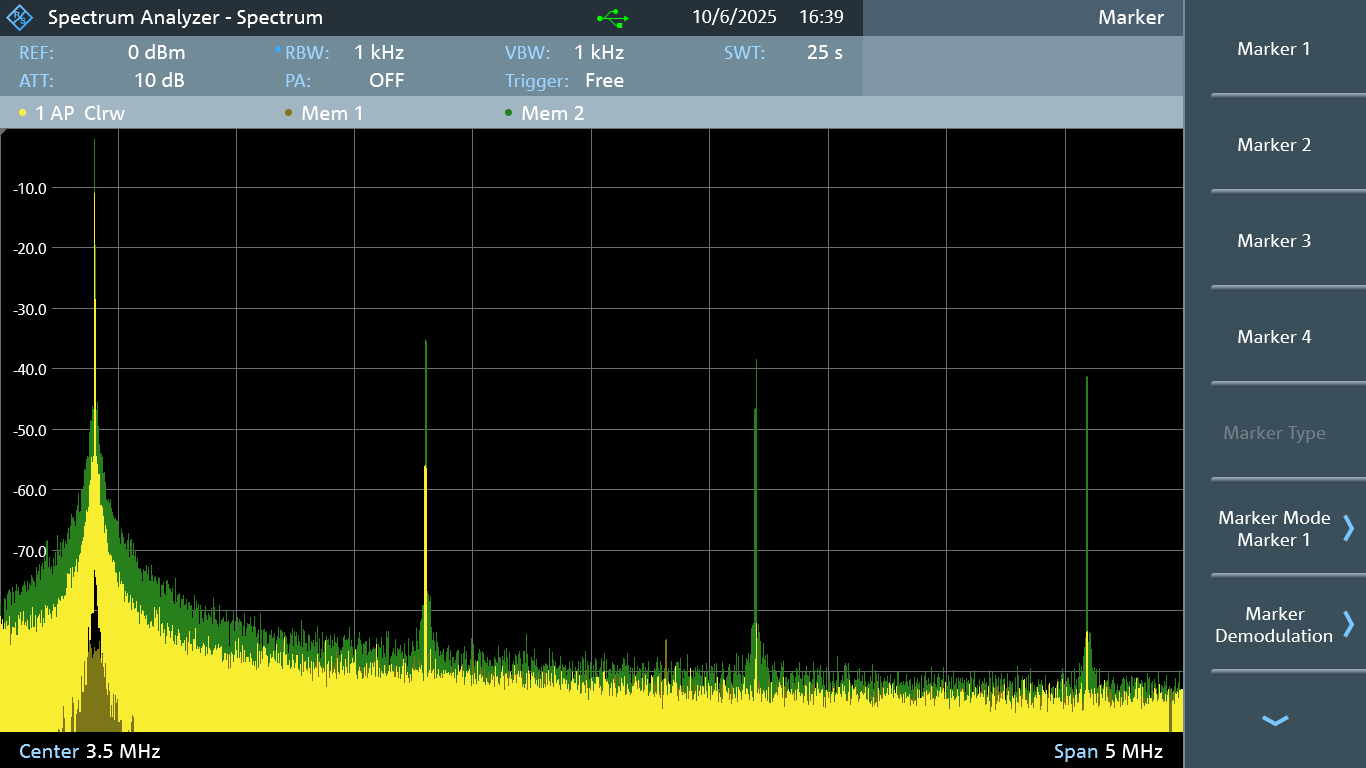
Zooming out to see the harmonics (the screenshot below covers the range 1 MHz to 6 MHz), you can see the beginning of a pattern which will occur at any frequency setting; the output is more distorted at high output levels, compared to low output levels. You can see that the yellow output (-10 dBm) has far lower harmonics than the green 0 dBm output.
Experimenting with the signal generator, a relay can be heard to click when exceeding 200 mVp-p, i.e. an amplifier is switched in. As a result, for the best signal, you’d want to keep the output setting to 200 mVp-p or lower.
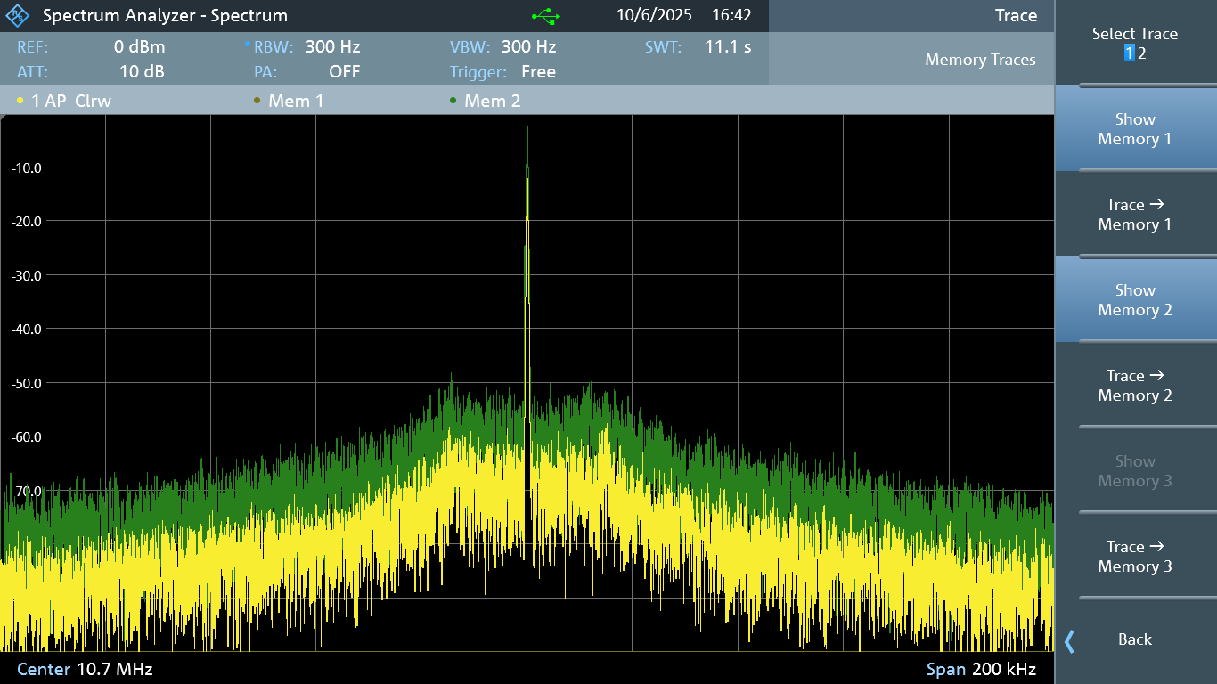
10.7 MHz Signal
Close-in, the 10.7 MHz output looks great. Again, the green trace is at 0 dBm output (632 mVp-p), and the yellow trace is at -10 dBm (200 mVp-p).
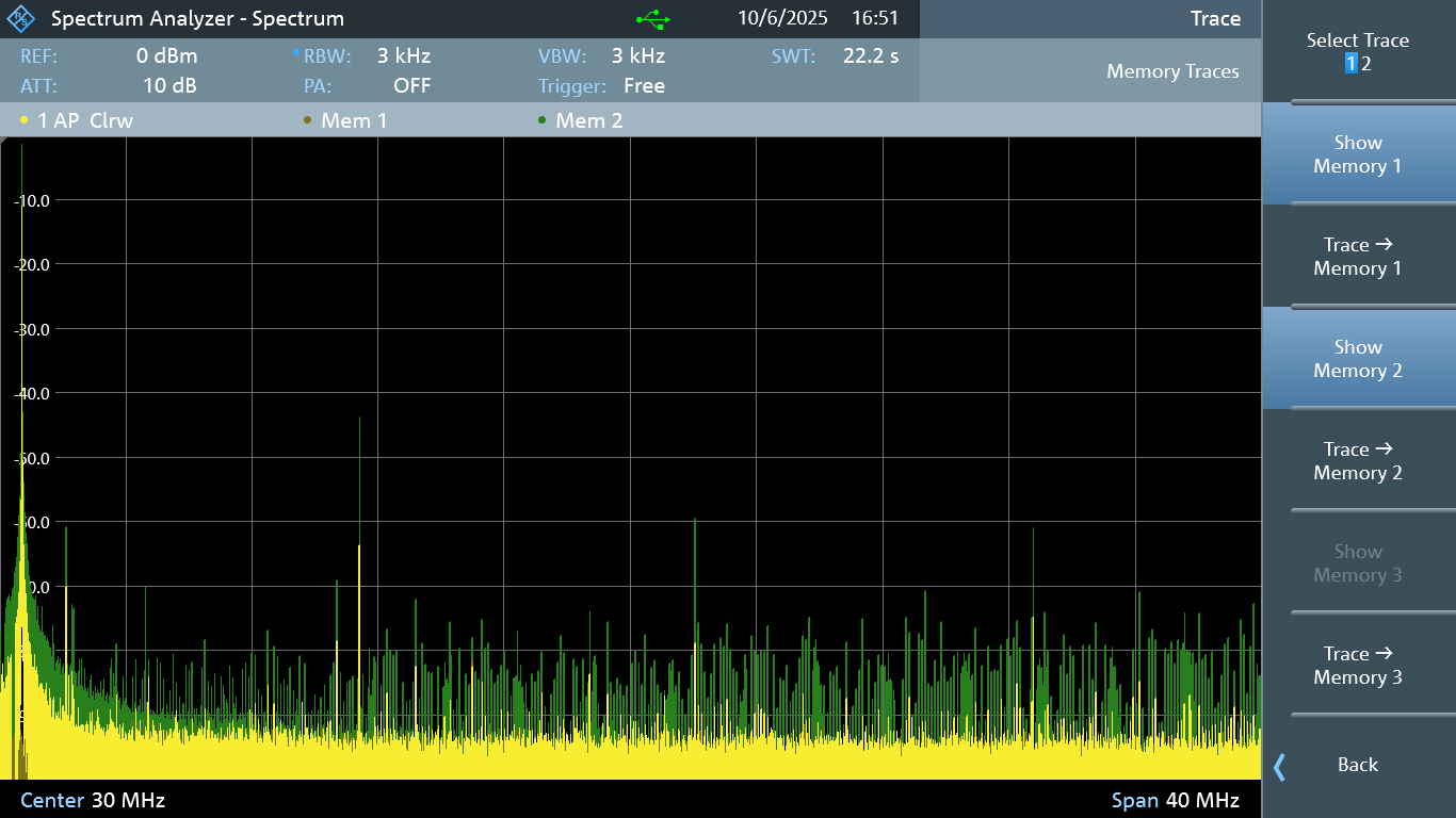
Zoomed out (the range in the screenshot below is 10 MHz to 50 MHz), you can see some of the harmonics and other distortion and noise, but it’s low.
21.4 MHz Signal
As with the other frequencies, the close-in output also looks great at 21.4 MHz. It is reassuring that the signal generator output is consistent across all the spot frequencies that were chosen.
Zooming out a bit more, you can see some non-harmonic distortion. This isn’t pretty, since it wouldn’t be as easy to filter out, and is certainly something to watch out for, since it may end up being in your desired bandwidth of interest.

Zooming out further (the range is 10 to 90 MHz in the screenshot below):

Internal Amplifier Noise
One thing that wasn’t easy to see in the earlier screenshots, is the noise beyond the supported frequency range of the signal generator. The screenshot below (which covers a 500 MHz range) shows it more clearly; you can see that when the internal amplifier is enabled (i.e. when the signal amplitude is higher than 200 mVp-p), you’ll see that green noise visible in the screenshot, versus the yellow noise when the amplitude was set to 200 mVp-p. The green output isn't ideal, but it isn’t too bad in the space of things. It’s something to be aware of.
Note that this isn’t common-mode noise, so no ferrites around the coax will solve this. It is actual noise from the internal amplifier inside the signal generator, and if it causes an issue, then you either need to drop the output to 200mVp-p or below, or a filter would need to be used. But I can imagine for almost all circumstances, that noise beyond the instrument’s frequency range won’t be much of an issue, and could always be filtered out by external circuitry if required, as mentioned. It might even be possible to modify the instrument to have a lower frequency cut-off for any output filtering, but I've not taken the unit apart and don't know if that is feasible or not.

Modulation
For the following AM and FM modulation experiments, I set the carrier frequency to 1.4 MHz, with an amplitude of 200 mVp-p (-10 dBm).
The DGE1030 doesn’t have an external modulation input, but you can use internal signals. I selected a sine wave to be the modulating signal.
Amplitude Modulation (AM)
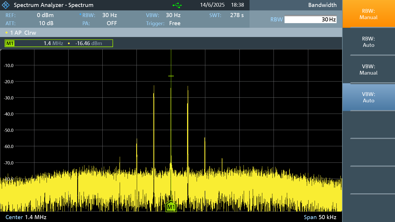
The screenshot below shows a 2.5 kHz tone, with a modulation depth of 100%. It’s near-perfect.
You’d expect to see two spikes at 2.5 kHz offset on either side of the carrier, and the extra spikes at 5 kHz look incorrect, but this is really not bad; the spectrum analyzer reveals a lot since the vertical scale is logarithmic, and in reality, the power in those 5 kHz spikes is tiny, at about 30 dB lower than the 2.5 kHz offset spikes, i.e. a thousandth of the power.
If you’re curious, this is what the output from a different signal source looks like; the screenshot below shows a signal generated by a R&S MXO 4, i.e. a lot more expensive:

Frequency Modulation (FM)
The screenshot below shows a 1 kHz tone as the modulating signal, and the frequency deviation was set to 2.5 kHz. The output visually looks plausible (it's not as easy to mentally predict the precise output spectrum for FM).
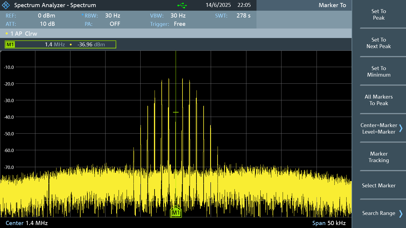
Here’s a comparison with a R&S MXO 4 tasked with producing a signal with the same parameters, and you can see it looks near-identical.
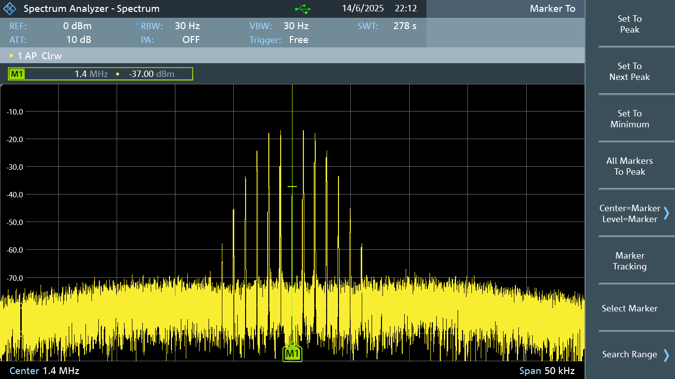
The conclusion is that the FM capability is working fine!
Low-Level Signals
The DGE1030 is configurable down to 1 mV p-p, which is not bad; that’s about -56 dBm. If you’re going to need lower-level signals, you’ll need external attenuation of course.
The screenshot below shows a sine wave output at 1.4 MHz and 1 mV p-p, displayed at a span of 1 kHz.

Square Wave Output
1.4 MHz Signal
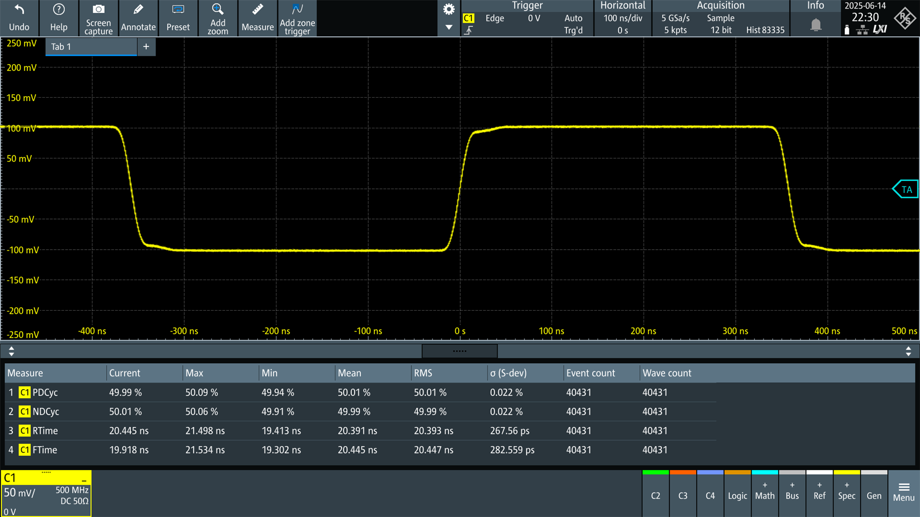
The screenshot below shows a 1.4 MHz square wave at 100 mV p-p. It’s very usable, and rise and fall times are just under 20 nanoseconds.
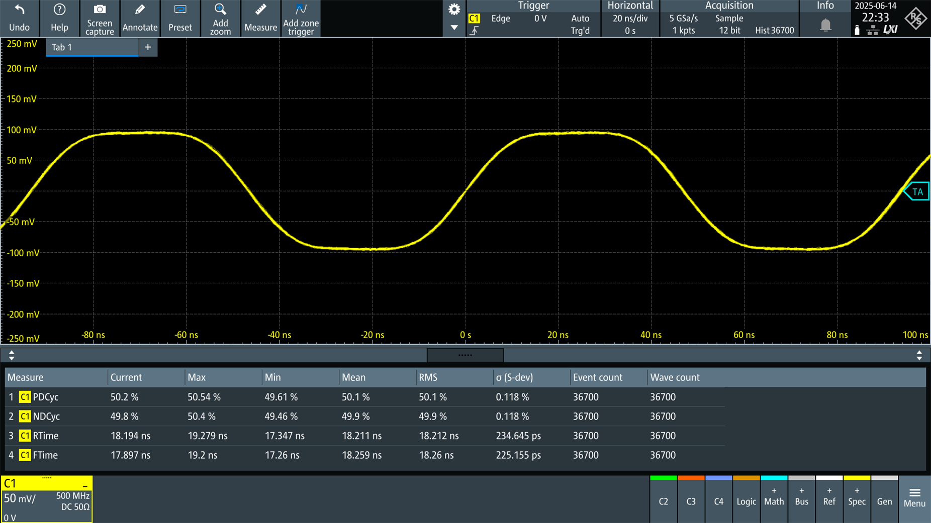
10.7 MHz Signal
The rise and fall times remain the same, and so the square wave won’t visually appear to have very perpendicular edges at 10.7 MHz.
The instrument can output in square wave mode at up to 15 MHz, however it will look sinusoidal at that frequency (not shown).
5 MHz Signal with 3.3V Logic Levels
The instrument was switched to high impedance output, which allowed the offset to be configured to be 1.65V, and the amplitude set at 3.3V p-p. The screenshot below shows a very reasonable waveform output (the 'scope was connected with a coax cable, and the 'scope was set to 1Mohm input impedance for this test, and the Pulse Output test discussed next).

Pulse Output
The instrument can be set to a pulse mode, which looks like a square wave, but you can select the duty cycle. For instance, the screenshot below shows a 1 MHz signal with 3% duty cycle, with amplitude and offset configured for 3.3V logic levels.
The duty cycle granularity and range depend on the configured output frequency.

The instrument provides a limited, small rise and fall time adjustment range when in the pulse output mode. If you zoom in to an edge, you’ll see that the pulse edges are composed of several steps. Unfortunately I forgot to grab a screenshot, I will add it at a later stage.
Anyway, long story short, for best fidelity, you’ll want to use the square wave mode if possible, otherwise, be aware that the pulse output mode edges won’t be as clean due to the nature of how they are generated. It may not be a very big issue, since one can often just use a microcontroller to generate logic-level pulses if required.
Programmability / Remote Control
By pressing the Utility button on the instrument, you can access a menu where the USB connection can be switched from PC to ‘USB TMC’. Once that’s done, your PC will see a ‘USB Test and Measurement Device’ connected. It will have a unique identifier such as:
USB0::0x5345::0x1235::24500822::INSTR
The instrument can be controlled from a variety of off-the-shelf software, or from your own code (for instance using Python). I couldn’t find the command reference manual for the DGE1000 series, but the commands from the DGE2000 PDF manual worked.
Sending the standard identification query from the PC, the instrument reported the following response:
OWON,DGE1030,24500822,SCPI:99.0\sFV:V1.0.4.4.0\n
The following commands are used to output a sine wave at 100 kHz, 100 mV p-p:
SOURCE1:FUNCTION:SHAPE SINUSOIDSOURCE1:FREQUENCY:FIXED 0.1MHzOUTPUT1:IMPEDANCE 50OHMSOURCE1:VOLTAGE:LEVEL:IMMEDIATE:OFFSET 0mVSOURCE1:VOLTAGE:LEVEL:IMMEDIATE:AMPLITUDE 100mVppOUTPUT1:STATE ON
What did I like?
The instrument, while basic, is quite competent. It performs all the key things I’d want 95% of the time. The instrument performs well for sine and square wave generation, which are the two key modes most users would use. Output quality is qood, especially at 200 mVp-p and lower, but it’s not bad beyond that although there is some additional distortion and noise.
The AM and FM modulation will come in very useful when building or testing radios.
Since it operates from a DC 5V supply, it has some isolation from ground, although that depends on the power supply.
The instrument is really compact, and silent (no fans!), and feels well constructed.
What didn’t I like?
Not a big deal for me, but it is missing more advanced features such as external reference input, and there are no configuration options for noise generation (it’s either noise or no noise, with no other parameters).
It’s quite annoying that the output level cannot be directly set in dBm (I had to keep converting manually between mV p-p across 50 ohm, and the equivalent dBm value).
I would have liked to have a touch screen, because it will get tiresome navigating some of the more nested menu paths, for example, when choosing one of the many internal arbitrary waveforms (but for basic tasks, the menu is certainly not complicated to use; I did not need to read the user manual).
Also, so far there doesn’t seem to be any firmware upgrades for the instrument. For the things demonstrated in this blog post, I didn’t notice any bugs, but that doesn’t mean none exist of course.
Summary
I was surprised that I liked the DGE1030 as much as I did. It works well, and I would be confident in the waveforms that it outputs for typical use-cases, although it’s still often worth double-checking your settings with an oscilloscope regardless of which signal generator you’re using.
I didn't test some of the features, such as the large quantity of built-in arbitrary waveforms, or the PC waveform creation software.
Signal outputs were examined at a range of frequencies, and the output looks good close-in to the frequency of interest, and even when zoomed-out, harmonics are at reasonably low levels. I didn’t test at audio frequencies (I will do that another day), I expect it will have distortion low enough for working with circuitry intended for speech applications, and for testing audio amplifiers in general, provided one isn’t interested in ultra-low distortion/noise.
Overall, I think it’s worth considering this instrument if you need a signal generator.
Thanks for reading!


