


When I view YouTube and other videos of engineers and technicians using a scope probe with a normal ground strap to make high-frequency measurements, I cringe as the results speak for themselves with the scope display showing far worse than expected spikes and high-frequency noise. A couple of examples are DC-DC Converter output ripple & noise measurement of the output voltage and a high-frequency (>10 KHz) PWM FET Drain to Source measurement.
The problem occurs with the ground connection of the scope probe. Most people start with the default ground strap on a 10X or a 1X probe. These are usually at least 3" long and can go up to a few feet long. When connected to the circuit to be measured, the scope probe plus ground strap form a loop antenna. And since the scope probe plus the scope input channel have a high-impedance (typically 10 MΩ for a 10X and 1MΩ for a 1X), this "loop antenna" easily picks up any stray RF signal nearby including: AM/FM/TV broadcast stations, 50/60 Hz Fluorescent Lighting, Motors with brush commutators, and more. The picked-up RF signal is in addition to the desired signal from the PCB or circuit. Therefore, the scope reading is essentially a sum of the wanted circuit signal and the unwanted RF signal. The signal seen on the scope can't be relied upon under these conditions.
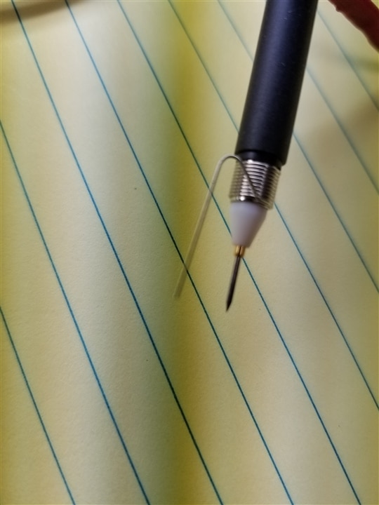
Fortunately, there's a way to minimize the RF pickup down to an insignificant amount (in most cases). To accomplish this requires the scope probe ground strap to be shortened severely. In fact, it needs to be eliminated. But we still need a ground reference for the scope. The answer is to make the scope probe connections coaxial. The best way to explain this is with a picture. Please refer to the first photo below. Most brand new scope probes come with a small kit of parts that includes a coiled spring that's the diameter of the probe near (but not at) the tip with the end of the spring wire bent such that it's parallel to the scope probe's center conductor. In order to install this coaxial ground spring/pin, the scope probe's hook tip must be pulled off the end of the probe and replaced with the ground spring. The ground spring goes over a cylindrical metal ground connection that's about 1/3rd of an inch behind the probe tip. Just make sure the end of the ground spring wire is pointing the same way as the probe's center conductor. This will shorten the total scope probe loop length from (+) to (-) from about 5" min using the shortest ground strap, down to 1/2" to 1".
If you don't have a ground spring adapter, you can make one from bus wire. Use about AWG #18 - #20 and wrap 4 or 5 turns around the ground area behind the center tip. For measurement of DC-DC Converter output noise and ripple, I recommend using a 1X probe with the ground spring made from a radial-lead 0.1 uF MLC Cap with X7R dielectric. Wrap one lead around the probe's ground area behind the probe tip and the other lead gets wrapped around the probe tip's center conductor with 2 to 4 turns of the Cap's lead. This has been accepted as an industry-approved way of measuring switching power supply ripple and noise (AKA PARD, for peak and random deviation) since the early 1980s when I worked at LH Research, one of the first Switch Mode Power Supply (SMPS) manufacturing firms. The Cap lead that wraps around the probe's ground is then brought out to be parallel with the probe's center conductor, much like the first photo below.
This far shorter probe loop length will drastically reduce any RF pickup. For most applications, I recommend the 10X probe, leaving the 1X probe with the cap for power supply (SMPS) ripple and noise measurements.
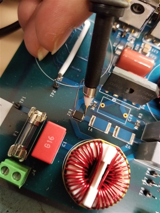
Now, there is a caveat. Please refer to the second photo below. The shows an SMD diode being probed with a coaxial probe. Notice how short the total loop length is for the measurement. In order to use a coaxial probe effectively, it's assumed that there's a ground terminal close enough to make the measurement using both the probe's center conductor and the spring ground pin. This is not always the case in realistic circuits. My recommendation for circuit probing where the ground is not close to the node being measured is to keep the scope probe ground as short as possible.
Additionally, it's important to use an appropriate ground for the measurement. Just because two grounds on a PCB are electrically connected together doesn't mean they're at the same potential. They're probably pretty close for DC, but for high-frequency AC, there can be up to a few volts or more of difference in grounds. It's best to use the closest ground that's part of the immediate circuit you're probing. For example, if you're probing a switching N-CH MOSFET, use the ground nearest the FETs Source (if it's ground referenced) and not some other ground that's part of a control circuit.
As a reminder, always use a scope probe with a bandwidth at least as high as you're scope's analog bandwidth and preferably higher. If you're using a 200 MHz BW scope and a 200 MHz BW Scope probe together, and you want to accurately measure a 200 MHz signal, you cannot as the scope by itself will read 3dB lower than the actual signal level and the limited BW probe will cut the measurement by another 3 dB for a reading of 6 dB less than the actual signal level. The math on this comes out to a ratio of 10^(-6dB/20) = 0.501 0r more about 50% less than the actual signal level. If you take the same situation except use a 350 MHz BW probe, now the measurement will read about 70.7% of the actual signal level.
However, if you're not concerned about scope voltage measurement accuracy and more concerned about the waveform and frequency content, then you might be able to measure a signal of 50% or more higher in frequency than the scope is rated for. This works for both analog and digital scopes, however, a digital scope cannot measure any signal that's higher than 50% of it's sampling frequency as you'll get artifact and won't know what's legitimate signal and what's not. This is called the Nyquist frequency.
Top Comments
-

michaelkellett
-
Cancel
-
Vote Up
0
Vote Down
-
-
Sign in to reply
-
More
-
Cancel
Comment-

michaelkellett
-
Cancel
-
Vote Up
0
Vote Down
-
-
Sign in to reply
-
More
-
Cancel
Children