


Table of Contents
Introduction
I have a few simple tools for generating RF signals, and they all have benefits and disadvantages. I recently decided to give a frequency synthesizer a shot. Could it be used as a crude RF signal generator tool? Time to investigate! This blog post shows the key findings.

As will be seen, the results are generally very good, however, there are some problems too, and in terms of price-performance, I have alternative suggestions that I think are much better.
What Is It?
It’s a board based around a MAX2870 frequency synthesizer chip (PDF datasheet), which generates a signal at a chosen frequency in the range of 23.5 MHz to 6 GHz. That’s it, pretty much! The touch-screen menu allows users to choose a fixed frequency or perform a sweep operation. Several output power levels are selectable (four settings, supposedly in steps of 3 dB). The device is powered via USB. It should be possible to control the device frequency via USB, but I could not figure that out.
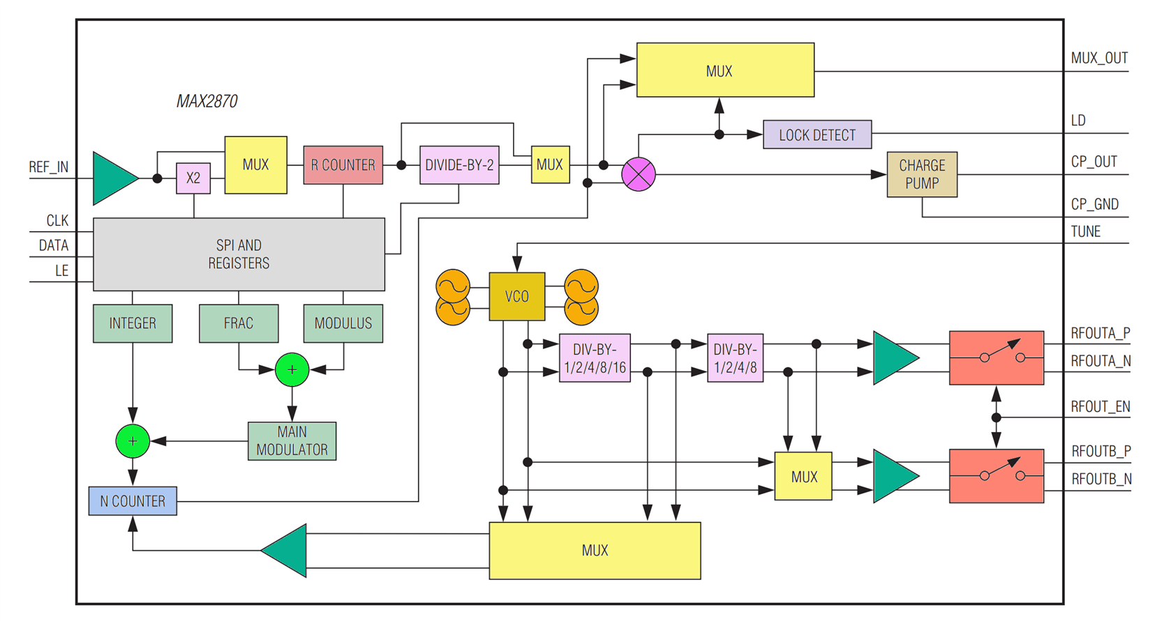
Internally, the MAX2870 uses a phase-locked loop (PLL) and it contains an integrated oscillator (VCO), so that very little external parts are needed; the main external thing that is required is the PLL loop filter (a network of resistors and capacitors).
The underside of the device has a removable PCB cover. In the photo below, the right side of the board contains the MAX2870 chip. Underneath the LCD flat-flex, is a GD32F103 chip (near-identical to STM32F103).

Is it a Sine Wave?
It is not. And that’s quite normal. It is closer to a square wave. Sometimes, you might actually want a square wave, for instance, if you’re driving some RF mixers. Furthermore, it’s often not such a big deal to convert to a sine wave by filtering off the harmonics. What can be more important is where the ‘spurs’ are, which are spurious unwanted signals that could be more difficult to filter out easily. Unfortunately most frequency synthesizers will generate spurs, and often the desire is to try to aim to have the spurs at frequencies that matter less.
Using It
It’s ultra simple to operate. I plugged a USB Type A to USB-C cable into a phone charger, and used it to power up the board (Note: a USB-C to USB-C cable will not work; the board is not wired up for that unfortunately).
Immediately, a menu appears, and it’s all self-explanatory. This is an instrument that can be learned and operated within seconds.

Measurements
I connected the output of the MAX2870 board to the spectrum analyzer (through a 20 dB attenuator since it’s good to be overly cautious when connecting something unknown; the measurements are compensated for that, so you don’t need to add 20dB to the values!).
The board has a 25 MHz crystal, and there is undoubtedly noticeable drift as expected while the board warms up, so it’s best not to use it for ten minutes or so.
First off, I decided to look at things from a distance, i.e., across a very wide frequency spectrum, to observe the level of harmonics where possible and just to see if there was anything too unusual going on! All looked good.


Next, it was time to zoom in and see things close-up; I used the same spot frequencies. The charts below show 100 kHz of spectrum, apart from the last trace, which shows 200 kHz of spectrum.


As can be seen from those spectrum traces, the fundamental output is quite constant. There isn’t much variation (about 1 dB) across almost the entire range of the frequency synthesizer. There’s only slightly more drop beyond 4 GHz, but it’s not much. For these measurements, I used a 0.6 m length of double-shielded RG316 coax, so there will be some loss there too. The visible spurs are quite low, they don't have a lot of power, especially for the low frequencies, and VHF.
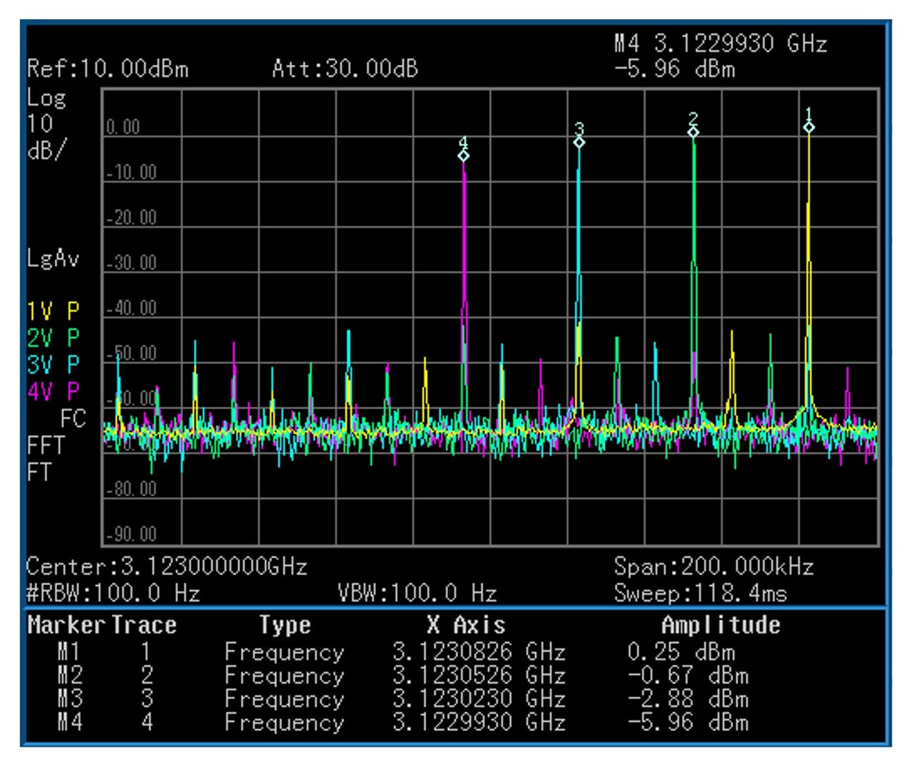
For all the measurements above, I used the maximum output setting on the board, which is labeled +5 dBm, which isn’t actually the case, as can be seen. I’m not sure of the reason (the MAX2870 datasheet is confusing; it suggests that the single-ended output power is the same as the differential configuration). The four overlaid traces show the effect of the four configurable output levels at four close-together spot frequencies. At this frequency range ballpark, the output measured from -6 dBm to +0.25 dBm across the four configurable levels.
Problems
I think these are the main problems with the device:
1. From the menu, frequencies can be entered in steps of 10 kHz, however, beyond some point past a GHz (I didn’t try to narrow it down) only 20 kHz steps are supported, even though the user can still enter values with 10 kHz steps. For those keen to use the board as a frequency synthesizer for radio communication, the 10 kHz minimum granularity could be an issue (it depends on whether the demodulation method will be analog, or software-defined).
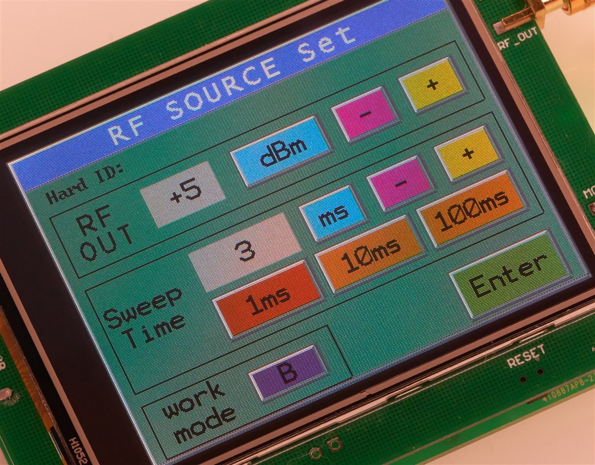
2. The sweep function (see the photo below to see how part of the configuration is set) isn’t as useful as it could have been. It only works in steps of 1 MHz, even though the user can enter values with 10 kHz granularity. It’s also buggy, for instance, the start and stop frequencies are never reached, just the in-between values, and sometimes I needed to restart the unit when reconfiguring the settings. If 1 MHz or higher sweep steps are acceptable, then the MAX2870 is quite fast at switching frequencies. It was possible to step across large frequency ranges (hundreds of MHz) with steps of just a few milliseconds.
3. The output could have been much better. The design uses a single-ended output. It would have improved the signal quality if there had been a transformer on the differential output.
4. The lack of documentation about the USB control!
5. Not a top-quality design. If you tap the device, it affects the output slightly. The loop filter capacitors could be upgraded to NP0/C0G, perhaps.
There are a few minor issues, too; for instance, there was a typo on the main menu! The button to stop the output was labeled ‘Quite’. There’s actually a quick fix for that; the microcontroller isn’t protected, and it is possible to read the contents (using any 'SWD' programming tool), and edit the text string in the binary data, and then re-write it to the chip. Mine is now labelled ‘Halt ‘.
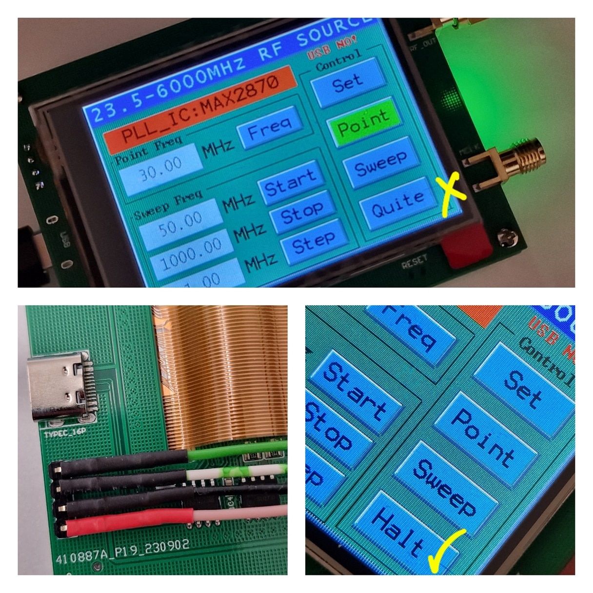
There are also a few minor software bugs, but powering off/on solves that. Incidentally, the device remembers the previous settings, so they are stored in non-volatile memory.
Recommended or Not?
For the above reasons, I’d have to say no. While it is a very convenient-to-use device, with actually very decent signal quality, and with a nice simple user interface, I don’t think it is worth the 45 GBP asking price. I think it would be far better to buy a MAX2870 board (or just the chip, but availability isn’t always good) and add your own microcontroller to it. The photo below shows there's really not much to it. Another benefit of doing that is then the frequency selection granularity can be increased, rather than be restricted to 10 kHz steps. If a custom board was to be made, then the MAX2871 is pin and software compatible, but with better performance.

There are also other options. For low frequencies, up to a few tens of MHz, direct digital synthesis is low-cost. Typical ICs to check out are AD9850 and AD9834. The AD995x series (e.g. AD9954) are great for up to 100 MHz or so.
For frequencies up to about 200 MHz, the Si5351 is usually an excellent choice. There’s some maths involved to control it, but it’s a solved problem, with plenty of open source code available.
Summary
The MAX2870 board that I tried had decent signal quality, and had an easy-to-use touchscreen interface, but it doesn’t justify the cost. It’s great to be able to have the access to signals across a huge range (21.5 to 6000 MHz), but there are better ways to get this capability. Personally I think it’s more worthwhile to buy a MAX2870 IC or a breakout board for it, and then add your own microcontroller and user interface.
Thanks for reading!
Top Comments