element14 Community
element14 Community
    Register Log In
  • Site
  • Search
  • Log In Register
  • Community Hub
    Community Hub
    • What's New on element14
    • Feedback and Support
    • Benefits of Membership
    • Personal Blogs
    • Members Area
    • Achievement Levels
  • Learn
    Learn
    • Ask an Expert
    • eBooks
    • element14 presents
    • Learning Center
    • Tech Spotlight
    • STEM Academy
    • Webinars, Training and Events
    • Learning Groups
  • Technologies
    Technologies
    • 3D Printing
    • FPGA
    • Industrial Automation
    • Internet of Things
    • Power & Energy
    • Sensors
    • Technology Groups
  • Challenges & Projects
    Challenges & Projects
    • Design Challenges
    • element14 presents Projects
    • Project14
    • Arduino Projects
    • Raspberry Pi Projects
    • Project Groups
  • Products
    Products
    • Arduino
    • Avnet & Tria Boards Community
    • Dev Tools
    • Manufacturers
    • Multicomp Pro
    • Product Groups
    • Raspberry Pi
    • RoadTests & Reviews
  • About Us
    About the element14 Community
  • Store
    Store
    • Visit Your Store
    • Choose another store...
      • Europe
      •  Austria (German)
      •  Belgium (Dutch, French)
      •  Bulgaria (Bulgarian)
      •  Czech Republic (Czech)
      •  Denmark (Danish)
      •  Estonia (Estonian)
      •  Finland (Finnish)
      •  France (French)
      •  Germany (German)
      •  Hungary (Hungarian)
      •  Ireland
      •  Israel
      •  Italy (Italian)
      •  Latvia (Latvian)
      •  
      •  Lithuania (Lithuanian)
      •  Netherlands (Dutch)
      •  Norway (Norwegian)
      •  Poland (Polish)
      •  Portugal (Portuguese)
      •  Romania (Romanian)
      •  Russia (Russian)
      •  Slovakia (Slovak)
      •  Slovenia (Slovenian)
      •  Spain (Spanish)
      •  Sweden (Swedish)
      •  Switzerland(German, French)
      •  Turkey (Turkish)
      •  United Kingdom
      • Asia Pacific
      •  Australia
      •  China
      •  Hong Kong
      •  India
      •  Japan
      •  Korea (Korean)
      •  Malaysia
      •  New Zealand
      •  Philippines
      •  Singapore
      •  Taiwan
      •  Thailand (Thai)
      •  Vietnam
      • Americas
      •  Brazil (Portuguese)
      •  Canada
      •  Mexico (Spanish)
      •  United States
      Can't find the country/region you're looking for? Visit our export site or find a local distributor.
  • Translate
  • Profile
  • Settings
Test & Tools
  • Technologies
  • More
Test & Tools
Forum If you need help on Test and Measurements, please post your question here!
  • Blog
  • Forum
  • Documents
  • Files
  • Members
  • Mentions
  • Sub-Groups
  • Tags
  • More
  • Cancel
  • New
Join Test & Tools to participate - click to join for free!
Actions
  • Share
  • More
  • Cancel
Forum Thread Details
  • Replies 48 replies
  • Subscribers 390 subscribers
  • Views 5520 views
  • Users 0 members are here
  • test
  • 测试
  • application
  • and
  • measurement
  • oscilloscopes
  • measurements
  • fluke
  • 示波器
Related

If you need help on Test and Measurements, please post your question here!

e14 Contributor
e14 Contributor over 15 years ago

This thread has been closed to new questions.

However, we welcome you to Post Your Question about Test & Measurement in the element14 Community Test & Measurement group. You'll find many fellow members and experts who have just the answer you're looking to find! 


Thank You, Your Friends at element14 Community

image


Jim Newell

Jim has worked for Fluke for a little over 31 years working in Manufacturing production and Quality assurance for the first 15 years. In the last 15 years he has focused on technical support as a Application Engineer for all of the Electrical Industrial products such as Handheld Oscilloscopes, Digital Mulitmeters and Power Quality Analyzers.  He enjoys the challenge of helping people and the famous saying the only dumb question is the one you didn’t ask are often joked about among his customers.


  • Sign in to reply
  • Cancel
Parents
  • e14 Contributor
    e14 Contributor over 12 years ago

    Hi Jim,


        I have a question that I believe is only somewhat related to testing though I hope you might be able to help.  I am trying to verify the functionality of a TI Webench regulator design.  To do this, I thought that I could breadboard the design using through hole components.  After wiring and double checking the design, the regulator gave no output voltage.  I get the sense that for some reason, the small tps regulator chip cannot drive breadboarded components.  Do you have any initial reactions?  Thanks for any help,


    - Zach

    • Cancel
    • Vote Up 0 Vote Down
    • Sign in to reply
    • Cancel
  • michaelkellett
    michaelkellett over 12 years ago in reply to e14 Contributor

    Breadboarding switch mode power supplies won't usually give satisfactory results and wiht modern fast devcies switching at > 100kHz is probably not worth the effort. However, you would expect some output. It would help (to help you) if you posted the circuit and a picture of the breadboard. Do you have an oscilloscope ?


    MK

    • Cancel
    • Vote Up 0 Vote Down
    • Sign in to reply
    • Cancel
  • e14 Contributor
    e14 Contributor over 12 years ago in reply to michaelkellett

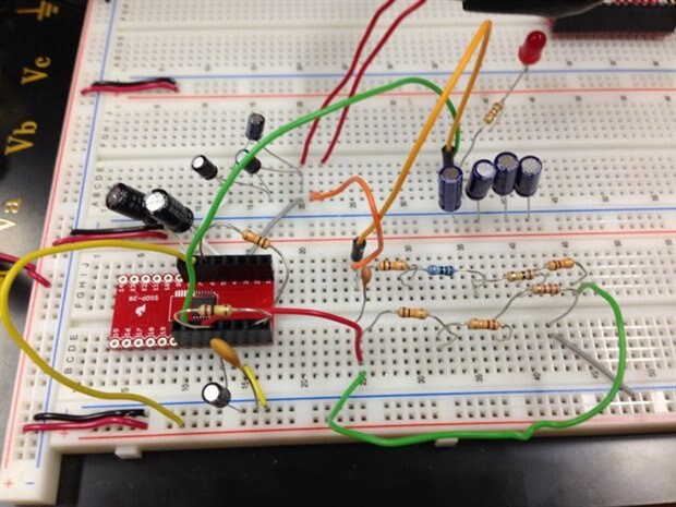
    Thanks for your reply.  We scrounged for the components so the breadboard is not very clean.  We do have an oscilloscope.  Just noise on the output side while the input was held at 12 with a DC Power supply.  The supply also registered no current draw.  We added a simple led and resistive load, but obviously no success

    imageimage

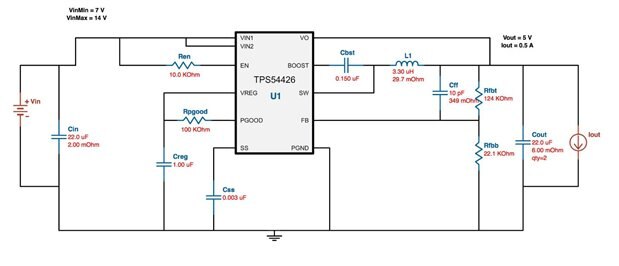
    This is the webench schematic, though I have one in eagle with the pin numbers.  The webench hides the fact that PGND and SW consist of 2 pins each

    • Cancel
    • Vote Up 0 Vote Down
    • Sign in to reply
    • Cancel
  • michaelkellett
    michaelkellett over 12 years ago in reply to e14 Contributor

    I've looked quite hard at your breadboard and I can't see L1 !


    This chip is absolutely not suitable for breadboarding - look at TI's recommended pcb layout on page 15 of the datasheet - they aren't joking  - you need a layout like this for the chip to work as advertised.


    Your breadboard layout, if it works at all, will be electrically very noisy and inefficient, probably unstable and may be bad enough for parasitic inductance in odd places to damage the chip.


    I wouldn't attempt to get a chip like this going in a new design without access to a 'scope - it is necessary to look at waveforms to make sure that it is operating correctly - a DMM is not enough.


    MK

    • Cancel
    • Vote Up 0 Vote Down
    • Sign in to reply
    • Cancel
Reply
  • michaelkellett
    michaelkellett over 12 years ago in reply to e14 Contributor

    I've looked quite hard at your breadboard and I can't see L1 !


    This chip is absolutely not suitable for breadboarding - look at TI's recommended pcb layout on page 15 of the datasheet - they aren't joking  - you need a layout like this for the chip to work as advertised.


    Your breadboard layout, if it works at all, will be electrically very noisy and inefficient, probably unstable and may be bad enough for parasitic inductance in odd places to damage the chip.


    I wouldn't attempt to get a chip like this going in a new design without access to a 'scope - it is necessary to look at waveforms to make sure that it is operating correctly - a DMM is not enough.


    MK

    • Cancel
    • Vote Up 0 Vote Down
    • Sign in to reply
    • Cancel
Children
  • e14 Contributor
    e14 Contributor over 12 years ago in reply to michaelkellett

    Hi Michael,


        thanks for the response.  I think at the time of this picture actually there are a few things missing, but I fixed them consequently.  The feedback hadn't been wired correctly in this picture.  The inductor is a through hole kind, thought the pins are quite small.  We weren't sure that they were connecting onto the breadboard so I alligator clipped them to some jumpers and stuck them in.  I think the inductor jumpers are the red one's going off the top of the page.  It seems like at this point, trying to breadboard these components is somewhat helpless.  Has anyone ever had an issue with Webench designs?  It was somewhat of a trivial test, but since we couldn't get any output I thought that we should investigate why that might be the case. 

    • Cancel
    • Vote Up 0 Vote Down
    • Sign in to reply
    • Cancel
  • michaelkellett
    michaelkellett over 12 years ago in reply to e14 Contributor

    If it simulates OK I would expect it to work as long as the layout is reasonable and the parts you use are the same as you simulated. You do need to be very careful with Cout and Cin which must be simulated with the correct esr values. The inductor must be simulated with the correct internal series resistance and must be rated for the peak current (check the data sheet to see how to work this out.)

    This is a reasonably fast switcher and won't be very forgiving, some of the older designs from National Semiconductor (now part of TI) in their 'simple switcher' range worked at much lower frequencies and you might get away with a worse layout.

    The reason that you really need a scope is that one of the most common ways that switchers malfunction is to pulse for  a short time, then stop, then start again and this can result in very large ripple currents and bad ripple on the supply but a DMM won't see it. Just to make life interesting some switchers deliberately work in pulse skipping mode at low powers.

    I wouldn't quite give up if you are really keen - try a much neater breadboard layout with a slower switcher or if you want to practice soldering try an "air" layout (ie DIL chip in a socket on its back with the parts soldered to the leads directly. Put the Cin and Cout and L on first so they get the really short leads. It's a bit of an art but can be effective.


    http://www.razorconcepts.net/img/sun/circuit.jpg


    The picture was pulled from the web - it seems that most people don't call it air wiring. Try googling "dead bug wiring"


    MK

    • Cancel
    • Vote Up 0 Vote Down
    • Sign in to reply
    • Cancel
  • e14 Contributor
    e14 Contributor over 12 years ago in reply to michaelkellett

    Thanks MK,


        Since we don't have single caps and resistors with the right values, I think dead bug wiring might be a bit difficult and our switcher is 400kHz I think.  I guess we'll try to do our best and see what happens.  I'll post some more results or questions after we play around with it a bit. 

    • Cancel
    • Vote Up 0 Vote Down
    • Sign in to reply
    • Cancel
element14 Community

element14 is the first online community specifically for engineers. Connect with your peers and get expert answers to your questions.

  • Members
  • Learn
  • Technologies
  • Challenges & Projects
  • Products
  • Store
  • About Us
  • Feedback & Support
  • FAQs
  • Terms of Use
  • Privacy Policy
  • Legal and Copyright Notices
  • Sitemap
  • Cookies

An Avnet Company © 2026 Premier Farnell Limited. All Rights Reserved.

Premier Farnell Ltd, registered in England and Wales (no 00876412), registered office: Farnell House, Forge Lane, Leeds LS12 2NE.

Follow element14

  • X
  • Facebook
  • linkedin
  • YouTube