


I am using an Omron H7EC pulse counter to display pulse output from a typical 2-wire reed switch water meter with pulse output. I am able to get pulses to show up on the Omron counter. However, I am planning to use 3-wire Hall-effect flow sensors for an irrigation project and I'd like to know how to hook up the Omron counter to display pulses from the 3-wire sensor and not use the more expense 2-wire flow sensors. 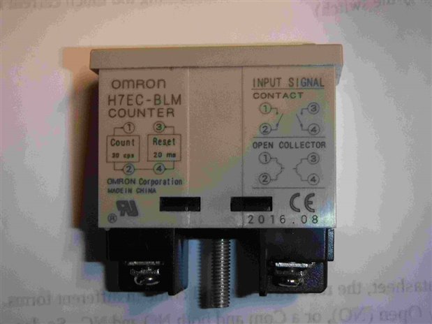
With Hall-effect flow sensors, there is a signal wire, and a 5vdc negative and positive wire for power. Using an Arduino board, I supply the 5vdc to the 3-wire flow sensor and the signal wire goes to the digital input on the Arduino. Metering shows up via the Arduino IDE and the serial monitor with my laptop/desktop.
So my question is how to run the 3-wire Hall-effect flow sensor to the Omron H7EC counter. I only need this as a quick test out in the field to verify flow sensor operation. Not worried about GPMs or liters/sec. as calibrated water flow but just raw pulse counts. Obviously, I'm going to use the signal wire for one connect, but that leaves the other 2 wires from this flow sensor which need the 5vdc power supply. So do I use a negative or positive wire to connect to the other terminal on the Omron counter? If so, is there going to be a 10k resistor or diode or some additional components on one of the other 2 wires to get the pulses to display on the Omron counter?

