

Hello all,
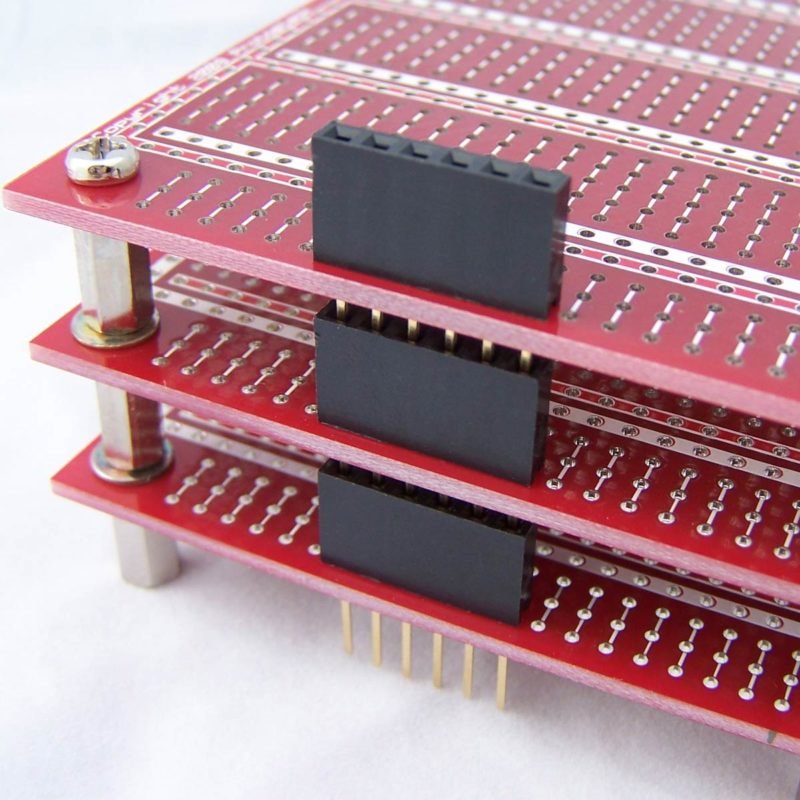
I have a project in which I am making a data logger for different temperature sensors and comparing both at the same time, the thing is that I have 2 boards, a main board with female socket pins like an arduino and connected to them is an adapter board that looks something like this
On the main board I have a USB male plug that powers the whole device with 5V but all my components use 3.3V so I have a LDO in the main board that lowers the 5V into 3.3V.
The problem is that I want to make it as a mobile device that you can take anywhere you want and log the data from the sensors, therefore I am adding a LiPo battery in the adapter board that is on the top and also adding a power management device that handles the recharging of the battery and the supply of the whole device and disconnects the battery from the system when the USB is plugged in a PC, I cannot change the design of the main board because it is more time consuming and would take more than a month to have the PCB made.
So after the short explanation of my device please see the image below to get a better understanding of my problem.
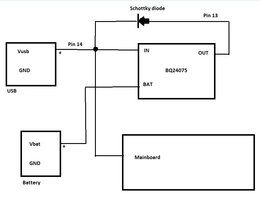
Would there be a problem if I place the connections like this? Would there be a short circuit where the pin 13 and 14 meet?
The BQ24075 has overvoltage protection, it supports up to 1.5A charge current, also has reverse current, short-circuit and thermal protection.
May be I have already answered my question but I just want a second opinion on this forum, multiple brains helping each other are better than having one confused brain trying to solve multiple problems at the time.


