element14 Community
element14 Community
    Register Log In
  • Site
  • Search
  • Log In Register
  • About Us
  • Community Hub
    Community Hub
    • What's New on element14
    • Feedback and Support
    • Benefits of Membership
    • Personal Blogs
    • Members Area
    • Achievement Levels
  • Learn
    Learn
    • Ask an Expert
    • eBooks
    • element14 presents
    • Learning Center
    • Tech Spotlight
    • STEM Academy
    • Webinars, Training and Events
    • Learning Groups
  • Technologies
    Technologies
    • 3D Printing
    • FPGA
    • Industrial Automation
    • Internet of Things
    • Power & Energy
    • Sensors
    • Technology Groups
  • Challenges & Projects
    Challenges & Projects
    • Design Challenges
    • element14 presents Projects
    • Project14
    • Arduino Projects
    • Raspberry Pi Projects
    • Project Groups
  • Products
    Products
    • Arduino
    • Avnet Boards Community
    • Dev Tools
    • Manufacturers
    • Multicomp Pro
    • Product Groups
    • Raspberry Pi
    • RoadTests & Reviews
  • Store
    Store
    • Visit Your Store
    • Choose another store...
      • Europe
      •  Austria (German)
      •  Belgium (Dutch, French)
      •  Bulgaria (Bulgarian)
      •  Czech Republic (Czech)
      •  Denmark (Danish)
      •  Estonia (Estonian)
      •  Finland (Finnish)
      •  France (French)
      •  Germany (German)
      •  Hungary (Hungarian)
      •  Ireland
      •  Israel
      •  Italy (Italian)
      •  Latvia (Latvian)
      •  
      •  Lithuania (Lithuanian)
      •  Netherlands (Dutch)
      •  Norway (Norwegian)
      •  Poland (Polish)
      •  Portugal (Portuguese)
      •  Romania (Romanian)
      •  Russia (Russian)
      •  Slovakia (Slovak)
      •  Slovenia (Slovenian)
      •  Spain (Spanish)
      •  Sweden (Swedish)
      •  Switzerland(German, French)
      •  Turkey (Turkish)
      •  United Kingdom
      • Asia Pacific
      •  Australia
      •  China
      •  Hong Kong
      •  India
      •  Korea (Korean)
      •  Malaysia
      •  New Zealand
      •  Philippines
      •  Singapore
      •  Taiwan
      •  Thailand (Thai)
      • Americas
      •  Brazil (Portuguese)
      •  Canada
      •  Mexico (Spanish)
      •  United States
      Can't find the country/region you're looking for? Visit our export site or find a local distributor.
  • Translate
  • Profile
  • Settings
Test & Tools
  • Technologies
  • More
Test & Tools
Forum Fuse /Power supply troubleshooting
  • Blog
  • Forum
  • Documents
  • Files
  • Members
  • Mentions
  • Sub-Groups
  • Tags
  • More
  • Cancel
  • New
Join Test & Tools to participate - click to join for free!
Actions
  • Share
  • More
  • Cancel
Forum Thread Details
  • Replies 19 replies
  • Subscribers 358 subscribers
  • Views 3684 views
  • Users 0 members are here
Related

Fuse /Power supply troubleshooting

gio_dude
gio_dude over 8 years ago

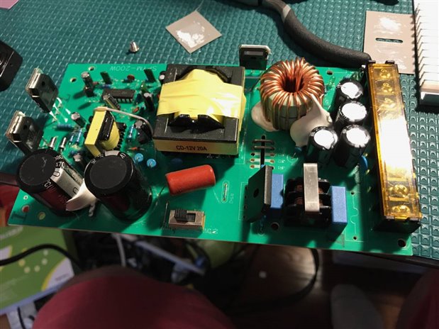
My friend at work built a 3d printer from a kit and his power supply went out. He said it made a pop noise and got no power from it. He ordered a new one already and gave me the old one and I would like to try and fix it.


Once I took it apart the first thing i saw was a fuse that looked blown. I got no continuity on the fuse from my multimeter. I unsoldered the fuse and the writing on it looks to be P5AL 250v or F5AL 250v.


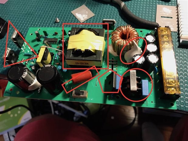
1) is there anything else you guys can recommend me testing or looking for.


2) I found this on amazon it looks to be the right fuse but can I solder leads to it.

https://www.amazon.com/BUSHIBU-F5AL-Fast-Blow-Glass-Fuses/dp/B01NAQH2TB/ref=sr_1_2?s=industrial&ie=UTF8&qid=1496014763&sr=1-2&keywords=F5AL+250v


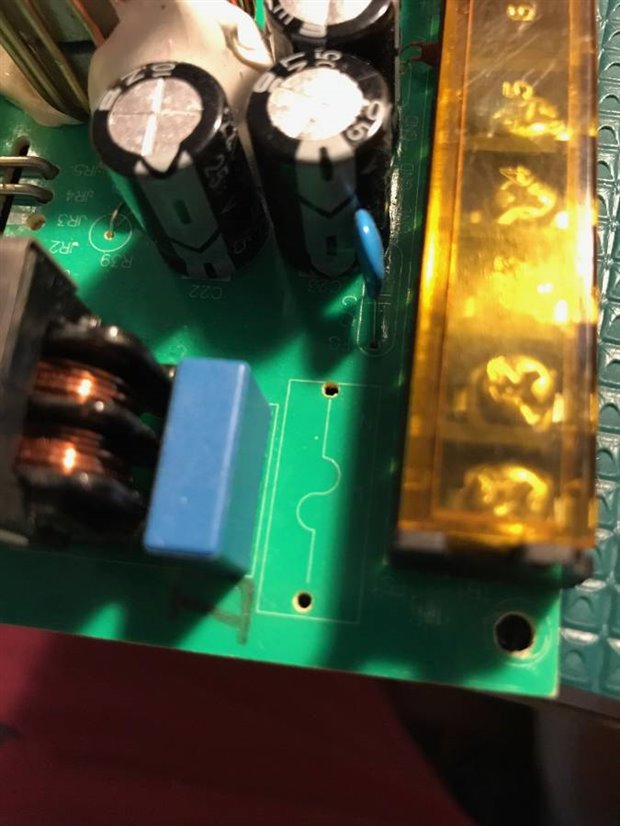
3) do you think I can put a holder on the PCB incase it blows again it would be easier to change. I attached a picture of where it was on the PCB.


imageimageimage

  • Sign in to reply
  • Cancel

Top Replies

  • jw0752
    jw0752 over 8 years ago +5
    Hi Giovanni, If you want to solder leads on the new fuse here is a procedure that I have used. File each end of the new fuse so you can see brass. This makes the solder adhere better. Use a hot iron and…
  • mcb1
    mcb1 over 8 years ago +5
    The supply pictured is a switchmode supply, and the fuse has definately gone bang. As jw0752 said it has lethal voltages and the first stage they rectify the mains voltage, filter it and then chop it to…
  • jw0752
    jw0752 over 8 years ago in reply to gio_dude +5
    Hi Giovanni, Let's start with in circuit testing. Do you have an analog multimeter? I ask as it is easier to visually make these tests watching a needle than trying to interpret a digital display that…
Parents
  • mcb1
    mcb1 over 8 years ago

    The supply pictured is a switchmode supply, and the fuse has definately gone bang.


    As jw0752 said it has lethal voltages and the first stage they rectify the mains voltage, filter it and then chop it to arrive at the final voltage, or voltages.

    Replacing the fuse is the least of your problems, you'll need to test some other parts to find died and took out the fuse.


    I was shown a really good trick for testing switch mode supplies.

    if you wire the mains through a 100-150W lamp, if there is a short, it will light the lamp, rather than creating minature explosions and causing more damage.


    Obviously some care is required, but the idea is the lamp is in series with the phase and can be achieved using a simple box with a lead and plug at one end, and cord socket on the other end.


    Mark

    • Cancel
    • Vote Up +5 Vote Down
    • Sign in to reply
    • Cancel
  • gio_dude
    gio_dude over 8 years ago in reply to mcb1

    Ok so not as simple as I would have liked it.


    Thank you everyone for you advise. I not sure I'm going to use this power supply again because I still don't trust my self yet with lethal voltages. I am in the USA so its 120v but still kind of scary.


    I would like to continue testing it even if I don't plan to power it up since I have already learned some much from just the one post. Sorry I'm very new.


    from what I'm reading I need to test most of the parts out of circuit. So before I start desoldering and getting confused I would like help identify parts because I'm still struggling with that a little.


    Triangle = spym 13009 mx38 is written on it. google says its a switch mode transistor is that how you guys are able to identify that the power supply is a switch mode one.


    square= ? not sure what this is.


    rectangle= says cv 400 b275jq on it


    oval= what is this goo its also near the caps on the left


    pentagon= has four pins + AC - is this the bridge rectifier?


    circle = not sure.


    image

    • Cancel
    • Vote Up +3 Vote Down
    • Sign in to reply
    • Cancel
  • DAB
    DAB over 8 years ago in reply to gio_dude

    As Mark and John have said.  Proceed cautiously.


    When the fuse goes, that means that there is significant problems within the remaining circuitry.


    Finding all of the broken or stressed components can be a time consuming task, which is why most of these devices are considered through away items.


    When I encounter a bad power supply, I usually just part them out.  Test the components I want to reuse and go on.


    Actually repairing the device is usually too expensive to contemplate.


    DAB

    • Cancel
    • Vote Up +2 Vote Down
    • Sign in to reply
    • Cancel
  • jw0752
    jw0752 over 8 years ago in reply to gio_dude

    Hi Giovanni,

    Let's start with in circuit testing. Do you have an analog multimeter? I ask as it is easier to visually make these tests watching a needle than trying to interpret a digital display that jumps around. Set your Ohm meter to Rx1


    The circle is very hardy and will not likely be damaged. It is a common mode inductor which filters out interference.


    The Pentagon is a bridge rectifier. It is possibly damaged. There are four diodes in this package and for each diode the meter should show continuity when the leads are hooked up one way and no continuity if they are hooked up in reverse polarity. Note there is a + and - which are the outputs and 2 side ways S's. This is the input from the AC power. The diodes are laid out between the + and the S's and between the - and the S's. You may see some resistance between the + and the - as well as between the two ss but you should not see a short.


    The oval under the glue is unknown but probably not the problem.


    The rectangle is a capacitor and probably not the problem as they can tolerate quite high voltages


    The Square is a switching transformer that is used to drop the high input voltage to the lower output voltage and not likely the problem.


    The Triagles are likely power MOSFETS. Looking at them from the front labeled side their leads are likely left to right Gate - Drain - Source. This is the most common configuration. You want to make sure that there is not a short between the Drain and Source on each one. Put you meter probes on the Drain and Source and then note the reading . Switch the probes and repeat. Even if these are not shorted they may have failed open so further testing may be necessary out of circuit. There is another device above the transformer that looks like a MOSFET but it is a Double Diode and used to turn the power from the switching transformer back into DC current. It is most likely ok but you can test it just like you did the bridge. From the center pin to each outer pins you should get a reading on the meter in one direction and not in the other.


    Try these tests and let us know what you find out. Do not plug in the unit until we have talked a bit more.


    John

    • Cancel
    • Vote Up +5 Vote Down
    • Sign in to reply
    • Cancel
  • kas.lewis
    kas.lewis over 8 years ago in reply to jw0752

    Thank you John for taking the time to explain this to those of us who don't know the ins and outs of power supplies image


    Kas

    • Cancel
    • Vote Up +3 Vote Down
    • Sign in to reply
    • Cancel
  • gio_dude
    gio_dude over 8 years ago in reply to jw0752

    Dab I agree probably easier to scrap it and buy a new one from all the post here and knowing my skill level I probably won't be able to fix it. this is more a learning thing at this point and boy have I learned a lot from these post.


    John thank you so much for the explanation of the parts that helps me put proper names for me to do more research and learn more about those components. I have a digital multimeter still learning how to use it.


    I removed the bridge rectifier and tested it in diode mode with the black probe on the minus pin i get nothing touching the red probe to each pin. when I put the red probe on the minus pin I get around .63 and .62 on the middle ac pins and .97 on the plus pin.


    the part behind the transformer says spym 30100 the it has a picture of two arrows going into each other with parallel lines in the middle.


    all this power supply has been sitting for about two months unplugged and unused I understand there is a risk to what I'm doing and i'm trying tot red lightly. I don't plan to power this unit unless I feel extremely safe.


    Thank you

    Giovanni

    • Cancel
    • Vote Up +2 Vote Down
    • Sign in to reply
    • Cancel
  • jw0752
    jw0752 over 8 years ago in reply to gio_dude

    A little follow up.


    The white glue is just for stabilizing components that do not have good mechanical attachments. The power supply may be used in an environment with lots of vibration and this keeps the heavy components from breaking loose.


    The Triangle components SPYM 13009 are not MOSFETs as I said before but switching NPN transistors as you mentioned. Incidentally these are similar transistors to the ones that are commonly used in the switching driver circuits of the common CFL (compact Florescent lights). The configuration of their leads from left to right are likely: Base - Collector - Emitter. Check between the Collector and Emitters for Shorts.


    Take general sequence of the circuit begins in the lower right corner where the AC power attaches and then works it way around the edge clockwise until the output attaches to the screw terminal at the upper right of the board. The circuit likely has current protection on the output so the most likely place for failure will be in the circuit along the lower and left edge. Once we get to the transformer and after failures will probably not blow the fuse but just shut down the switch. This is speculation as I can not do more than guess at the actual circuit without seeing it.


    John

    • Cancel
    • Vote Up +3 Vote Down
    • Sign in to reply
    • Cancel
  • jw0752
    jw0752 over 8 years ago in reply to gio_dude

    The bridge out of the circuit should give OL on the connection of the meter between the s and s. Between the plus and each s with the black probe on the plus you should get OL. If you put the red probe on the minus you should get OL to each of the s s. This assumes that the test polarity of your ohmmeter  circuit is like most of the meters I have seen.


    When you read your meter make sure you are aware of the "K" or "M" that may be displayed as these can drastically change what the numbers indicate.

    .63 is basically a short.  .63K is 630 ohms and .63M is 630,000 ohms. If you indeed got .63 ohms when you tested across the AC (ss) terminals then the bridge is bad and probably caused the fuse to blow.


    John

    • Cancel
    • Vote Up +3 Vote Down
    • Sign in to reply
    • Cancel
  • gio_dude
    gio_dude over 8 years ago in reply to jw0752

    Thank you I was wondering about the glue that makes sense now


    I attached some pictures of readings and the bridge rectifier mine doesn't have a tilde (side ways S) it just says AC which makes sense since that is the symbol for AC.


    my multimeter isn't auto ranging and after today I'm considering upgrading it.


    image

    imageimageimage

    • Cancel
    • Vote Up +1 Vote Down
    • Sign in to reply
    • Cancel
  • jc2048
    jc2048 over 8 years ago in reply to jw0752

    Giovanni is using the meter on the diode setting, so the reading is the forward voltage.

    • Cancel
    • Vote Up 0 Vote Down
    • Sign in to reply
    • Cancel
  • rachaelp
    rachaelp over 8 years ago in reply to gio_dude

    Giovanni Laucella wrote:


    Thank you everyone for you advise. I not sure I'm going to use this power supply again because I still don't trust my self yet with lethal voltages. I am in the USA so its 120v but still kind of scary.

    Hi Giovanni,


    Just for reference, even though you are in the US with "only" 120V, if you were working on an AC/DC converter that included power factor correction the nature of how the PFC works usually involves the voltage being boosted to much higher, so you could end up with voltages in the range of 400V on large capacitors so you are very right to be cautious when working on this type of circuit.


    Best Regards,


    Rachael

    • Cancel
    • Vote Up +2 Vote Down
    • Sign in to reply
    • Cancel
Reply
  • rachaelp
    rachaelp over 8 years ago in reply to gio_dude

    Giovanni Laucella wrote:


    Thank you everyone for you advise. I not sure I'm going to use this power supply again because I still don't trust my self yet with lethal voltages. I am in the USA so its 120v but still kind of scary.

    Hi Giovanni,


    Just for reference, even though you are in the US with "only" 120V, if you were working on an AC/DC converter that included power factor correction the nature of how the PFC works usually involves the voltage being boosted to much higher, so you could end up with voltages in the range of 400V on large capacitors so you are very right to be cautious when working on this type of circuit.


    Best Regards,


    Rachael

    • Cancel
    • Vote Up +2 Vote Down
    • Sign in to reply
    • Cancel
Children
  • mcb1
    mcb1 over 8 years ago in reply to rachaelp

    Here's a good reference for Power Supplies.

    http://www.hammondmfg.com/pdf/5c007.pdf


    The DC voltage on the filter capacitor for your supply with the Bridge Rectifier is 120 x 1.414 = 169.68 volts give or take a little.

    Caution is a good idea.


    The others are giving great advice, so I'm sure you'll eventually work out what went and took out the fuse.


    Mark

    • Cancel
    • Vote Up +2 Vote Down
    • Sign in to reply
    • Cancel
element14 Community

element14 is the first online community specifically for engineers. Connect with your peers and get expert answers to your questions.

  • Members
  • Learn
  • Technologies
  • Challenges & Projects
  • Products
  • Store
  • About Us
  • Feedback & Support
  • FAQs
  • Terms of Use
  • Privacy Policy
  • Legal and Copyright Notices
  • Sitemap
  • Cookies

An Avnet Company © 2025 Premier Farnell Limited. All Rights Reserved.

Premier Farnell Ltd, registered in England and Wales (no 00876412), registered office: Farnell House, Forge Lane, Leeds LS12 2NE.

ICP 备案号 10220084.

Follow element14

  • X
  • Facebook
  • linkedin
  • YouTube