

This blog documents focuses on the functionality of the Input Enable block of the electronic load that Robert Peter Oakes, jc2048 and Jan Cumps are designing. We're using an i²c port extender to drive this functionality. It will be mostly focusing on the firmware but let's also look at the electronics involved.
|
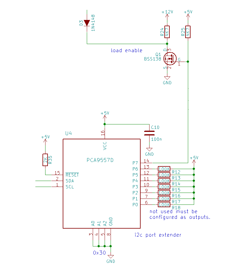
The circuit disables the output by pulling the signal that sets the load's current to ground. The switch that pulls it to ground is a FET.
The interface between that FET and the microcontroller is an i²c controlled port extender. We're using its P7 as the driver of that switch FET.
We'll have to create an RTOS task that puts all pins of the extender in correct mode. Then it has to listen and react on messages that indicate whether the input has to be on or off.
At the moment the task is only focusing on the single output pin of the port extender that we're using.
In the future this task may change into a more generic one that can set any of the available pin's function, then read and write as appropriate. We don't have to worry about that now. Nothing here prevents to make that generalisation later - we don't need it now. |
RTOS Tasks overview
| Task | Priority | Vital | Stack | Argument0 (schedule) | Comments |
|---|---|---|---|---|---|
| threadInputEnable | 10 | no | 1024 | 0 Managed by QUEUE_NAME_INPUTENABLE | reacts on a mail message to enable or disable the input |
RTOS MailBox overview
| MailBox | Message count | Comment | Functions |
|---|---|---|---|
| QUEUE_NAME_INPUTENABLE | 1 | wait: threadInputEnable() send: eloadInputEnable() |
(I mistakenly called all of this Output Enable initially. That's wrong. The load has an input)
SCPI Interface
| SCPI Command | status | Header 3 | Comment | Header 5 |
|---|---|---|---|---|
[:SOURce]:INPut[:STATe] <b> | todo | Set the input state to ON or OFF | INP ON INP OFF | |
| [:SOURce]:INPut[:STATe]? | todo | Query the input state | INP? |
Input Enable
The load is enabled on command, using RTOS MailBox and messaging.
The payload for a InputEnable message contains a boolean value that says if it's on or off.
typedef struct MsgInputEnable {
     bool value;
} MsgInputEnable;
The InputEnable task is started by RTOS. It inialises the Port Extender settings, then waits until it receives a message.
The i²c part is removed here for clarity
void *threadInputEnable(void *arg0) {


// ...

    mqd_t mq;
    struct mq_attr attr;


    attr.mq_flags = 0;
    attr.mq_maxmsg = 1;
    attr.mq_msgsize = MSGINPUTENABLE_SIZE;
    attr.mq_curmsgs = 0;
    mq = mq_open(QUEUE_NAME_INPUTENABLE, O_CREAT | O_RDONLY, 0644, &attr);


    while (1) {
        ssize_t bytes_read;
        bytes_read = mq_receive(mq, (char *)&d_msg, MSGINPUTENABLE_SIZE, NULL);


        /* wait for mailbox to be posted by writer() */
        if (bytes_read) {
            d_iotxBuffer[1] = d_msg.value ? 0x3F : 0xFF; // bit 7 low is output enable.
            if (! I2C_transfer(i2c_implGetHandle(), &d_ioi2cTransaction)) {
//                System_printf("I2C Bus fault\n");
//                System_flush();
            } else {
                bInputEnable_State = d_msg.value;
            }


        }
    }
}
The waiting doesn't take processor time. Check the DAC explanation to see how this is done. We're reusing the exact same RTOS mailbox mechanism here.
The state is stored as a variable in inputenable_impl.c.
An api function is provided to retrieve this:
// storage for the state
volatile bool bInputEnable_State = false;
// ...
bool inputenableImplGetInputEnable() {
    return bInputEnable_State;
}
The eload api (this is the generic interface for the whole instrument, it can serve events from the SCPI module and from other GUIs - hardware or software) provides two api functions to wrap this:
void eloadInputEnable(bool bEnable) {
    MsgInputEnable pMsg;


    // value has to be validated before it arrives here. We assume it's valid
    pMsg.value = bEnable;
    /* enqueue message */
    mqd_t mq;
    mq = mq_open(QUEUE_NAME_INPUTENABLE, O_WRONLY);
    if (mq != ((mqd_t)(-1))) { // only send data if the message queue has been initialised by the receiving end. Else our instrument isn't ready
        mq_send(mq, (char *)&pMsg, MSGINPUTENABLE_SIZE, 0);
    }
}
The SCPI implementation has two table entries to understand both set and get calls, and a service routine to fullfill the request. These routines call the eload api:
// ..
    {.pattern = "[:SOURce]:INPut[:STATe]", .callback = ELOAD_SetInputState,},
    {.pattern = "[:SOURce]:INPut[:STATe]?", .callback = ELOAD_GetInputState,},
// ..

static scpi_result_t ELOAD_SetInputState(scpi_t * context) {
    scpi_bool_t param1;

    /* read first parameter if present */
    if (!SCPI_ParamBool(context, ¶m1, TRUE)) {
        return SCPI_RES_ERR;
    }
    eloadInputEnable(param1);
    return SCPI_RES_OK;
}


static scpi_result_t ELOAD_GetInputState(scpi_t * context) {
    SCPI_ResultBool(context, eloadInputEnabled());
    return SCPI_RES_OK;
}
There is a reason for these three layers. Ask if you want to know them.
todo: investigate the i²c commands to set the port extender in the right initial state and drive it's output P7 high and low.
i²c communication
I'm using the NXP datasheet (PCA9557 is available from TI and NXP the one on my prototype is from NXP).
The address of our chip is determined by the pins A0 - A3:
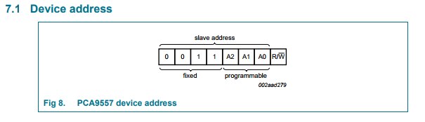
Because we've tied all of them to ground, our 7-bit address is 0x18.
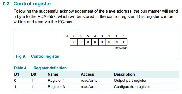
To have the right setup and give the right commands, we need to send instructions to two control registers.
Here are the relevant registers for setting the pin directions and setting an output value:
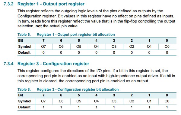
Our first communication will set all registers to output and drive them all high. That's going to be the initial state for our application.
We'll have to submit 2 times 2 bytes at initialisation, after setting the address:
The first time to set the direction.
- address + ~W
- 0x01 (output port register)
- 0xFF (all values high)
The second time we enable all as outputs.
- address + ~W
- 0x03 (configuration register)
- 0x00 (all as output)
Then, during operation, when setting and resetting the P7 of the IC, we have to flip the highest bit in the output port register:
- address + ~W
- 0x01 (output port register)
- if enable: 0x3F; if disable 0xFF (we are keeping all other pins high because nothing is happening with them in the current implementation of the load).
Here is the full implementation of the input enable task, with i²c commands:
void *threadInputEnable(void *arg0) {


    MsgInputEnable d_msg;
    d_ioi2cTransaction.writeBuf = d_iotxBuffer;
    d_ioi2cTransaction.readBuf = d_iorxBuffer;
    d_ioi2cTransaction.slaveAddress = PORTEXTENDER_I2C_ADDR;
    d_ioi2cTransaction.writeCount = 2;
    d_ioi2cTransaction.readCount = 0;


    // initialise and set output to off


    // first set all outputs to high


    d_iotxBuffer[0] = 0x01; // control register: select output port register
    d_iotxBuffer[1] = 0xFF; // set each bit high in the output register
    if (! I2C_transfer(i2c_implGetHandle(), &d_ioi2cTransaction)) {
//        System_printf("I2C Bus fault\n");
//        System_flush();
    }


    d_iotxBuffer[0] = 0x03; // control register: select configuration register
    d_iotxBuffer[1] = 0x00; // set each bit low so that all 8 pins are outputs (recommended state for unused pins)
    if (! I2C_transfer(i2c_implGetHandle(), &d_ioi2cTransaction)) {
//        System_printf("I2C Bus fault\n");
//        System_flush();
    }


    // from now on we only write to the output port register.
    // Value d_txBuffer[0] can be fixed outside the loop


    d_iotxBuffer[0] = 0x01; // control register: select output port register


    mqd_t mq;
    struct mq_attr attr;


    attr.mq_flags = 0;
    attr.mq_maxmsg = 1;
    attr.mq_msgsize = MSGINPUTENABLE_SIZE;
    attr.mq_curmsgs = 0;
    mq = mq_open(QUEUE_NAME_INPUTENABLE, O_CREAT | O_RDONLY, 0644, &attr);


    while (1) {
        ssize_t bytes_read;
        bytes_read = mq_receive(mq, (char *)&d_msg, MSGINPUTENABLE_SIZE, NULL);


        /* wait for mailbox to be posted by writer() */
        if (bytes_read) {
            d_iotxBuffer[1] = d_msg.value ? 0x3F : 0xFF; // bit 7 low is output enable.
            if (! I2C_transfer(i2c_implGetHandle(), &d_ioi2cTransaction)) {
//                System_printf("I2C Bus fault\n");
//                System_flush();
            } else {
                bInputEnable_State = d_msg.value;
            }


        }
    }
}
Top Comments