


| Previous Blog |
|---|
| Project R.A.G. - Blog #1 - Mission Briefing |
Blog #2 - Strapped In For Launch - Connectors
1. Introduction
Hi! This will be my second blog for the Robot Assisted Garden project, in this blog I will cover some custom designed connectors. As to every electronics project, we need a way to connect different boards, sensors, modules, between each other. If a connector on one of the sensor fails, that may not be a huge issue (but it can be), but if a connector on the power supply loosens up or fails, the whole device will shut down. Of course, for every application there are off the shelf connectors which are designed for that and tested for high and low temperatures, official IP ratings and so on. But of course, since the usual use case for those robust connectors is military, facilities, automotive, they tend to get pretty pricey. Since I don't need anything like that and am making a proof of concept module I will be designing my own connectors using 3D printing and some low cost off the shelf connectors.
For what do I need connectors?
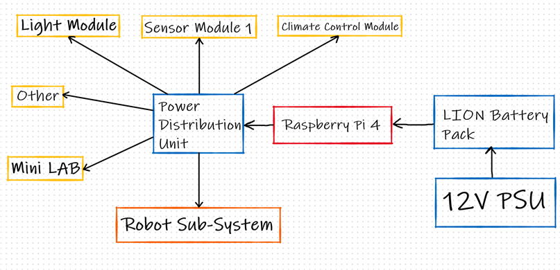
My project will have a modular design, where I'm going to have a central unit with the Raspberry Pi 4 which will control and communicate with the other modules in the project. The Raspberry will also control all of the power to the modules, since there will be a central power supply module backed up by a central battery bank in case of a power loss. In this way, if there is a power loss, the Raspberry can shut off unneeded modules like redundant sensor modules and so on. From there we can see that we need a connector for data transfer as well as a power connector to tie the modules between themselves.
Besides those 2 connectors which are used for connecting the different modules there is another connector I will be needing. As I've mentioned in the first blog, the robot will need to change it's head to perform different functions. Because there will be active components on the head of the robot, I need to get power and maybe another signal to the head of the robot somehow. One way to do this would be to have long cables which the robot could pull around as it's working, but those would catch on everything and just cause a big mess. My idea, why not design a sort of an automatic connector. It has to have 3 pins, and it has to engage when the to halves are close to each other, so I decided to go with magnets. Before going into the details on how I designed both of these connectors, let's make a short requirements list for both of them.
Requirements List
I will use this list as a main guideline to consider when designing these connectors, with sub-categories for both of the connectors for the things that are specific for both. But first, let's start with the ones which should apply to all of them with explanation as to why I think that is important:
- 3D printable and are possible to make at home
- It's easy coming up with a cool concept for how a connector can look and work, and it can probably be made using some hardware, but it maybe can't with 3D printing and normal tools. By this I mean, I don't want to go down the route where I'm designing my own custom pins which I have to make and so on, but rather, combine 3D printing with off the shelf parts, like 3.5mm connectors or barrel jack connectors.
- Humidity in mind
- These connectors are going to be in a project with plants and a lot of humidity, and while I cannot protect the magnetic one that much, I want to at least protect it's contacts from being directly accessible
- Simple to assemble
- There will be quite a few of these in the end in this project, so I don't want to spend half an hour on each one using glue and stuff like that. That's why I'll try using mostly mechanical bonds for these connectors, except where I need to use a bit of glue to hold in something
- Waterproof connector
- Support for 3.5mm jack
- Support for barrel jack
- Waterproof with use of small o rings
- Easily adaptable for different diameters of cables
- Locking connector
- Magnetic connector
- 3 pins
- Reason why I'm going with 3 pins is mostly because of one of the sensors I plan on using this way, as well as servo motors. The sensor in question is the soil humidity sensors which uses 3 pins, one for power, one for ground and one for data, while servos also use one for power, one for ground and one for PWM. In this way I can use both of them only with this one connector, of course, this means I'll need to have some kind of circuit between this and the microcontroller which would switch between the servo motor mode and sensor mode.
- Pull itself together and resist vibrations
- The connector needs to connect even when it's not completely engaged by the robot (let's say from 5-10mm apart) and it shouldn't disconnect from vibrations which will come during the robot operation. This can be solved with clever design of the whole connector while the connection itself can be secured by using 2 smalls magnets.
- 3 pins
Previous Work
This is something I've already tackled in one of my previous blogs: 3D Printed Locking Connector - Type 1 . In the blog I covered in detail the design process for that connector, and the waterproof connector I will cover now is an upgraded version of that. That connector turned out pretty good, one thing I redesigned was how the cable is mounted, since I didn't like the way I did it at all. Another thing is that I changed is that the first connectors body had to be printed at once with the connector locking nut, which on one hand is good, because that's where the nut should be, but I found a better solution for that. Here is how the old connector looked like.
2. Waterproof Connector
As I've already said, this will be an upgraded version of my first 3D printed connector. There are a few changes to the body of the connector, how it's printed, with the biggest changes being the O rings and how the cable is mounted. The key at the end of the connector will remain the same, and it is compatible with the panel connectors for this connector that I have already designed.
Idea
The main idea here was to copy the old design which was pretty good and upgrade it with rubber O rings. Rubber O rings are great thing, I managed to find a set with many different sizes for around 10$ and it proved to work great with 3D printing. It's a bit tricky to get the dimensions just right for embedded O rings, but I managed to do so after a few tries. In the next part I will go over the design for all of the components of the connector. The parts which are labeled as 3.5mm variant and barrel jack variant are for the panel mount part of the connector which is different in regards for the type of connector which is used.
Design
| {tabbedtable} Tab Label | Tab Content |
|---|---|
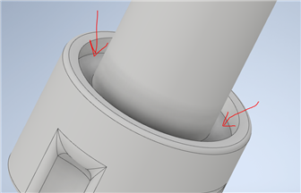
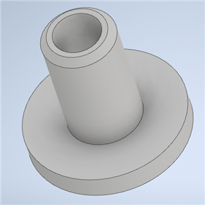
| Body of the Connector | Body of the connector This is the main part of the connector as the name implies. The length of the body of the connector can be made shorter for a shorter version of the connector. Here is a technical drawing for this part:
The weird shape at the top is the "key" for the other part of the connector. When you plug in into the other, it will stop this connector from turning in circles while you tighten it. As you can see at the top as well there is a shallow ring shaped hole, that is the part which is going to go over the O ring which is mounted on the panel connector. There are 2 O rings that can go on this part of the connector, one is in the small channel near the tip of the connector pictured here.
The other O rings goes where the cables enters the connector. My design philosophy was that the mushroom gets glued to the cable so when you tighten that mushroom down with the cable nut, it will compress the o ring and make that seal much better. The slot for the O ring can be seen on this picture.
Besides that, other things to point out is the thread at the top which is used for the cable nut. This of course isn't a standard thread, I designed it myself to be strong when 3D printed, the way I did this is by coiling a trapezoid around the body of the connector making the cut. The cable nut has the same thread as you will see soon, with just a slightly bigger radius due to the tolerances of 3D printing. In the end, this is how the model turned out.
|
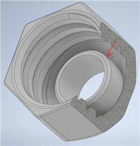
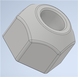
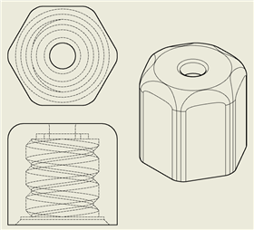
| Locking Nut | Locking Nut This here is the locking nut which goes over the body of the connector, it can slide up & down it, and it threads onto the panel connector to lock the connector in the place.
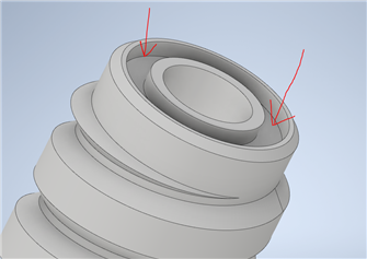
The thread on this nut was designed in the same way as for the cable nut and the thread on the body of the connector, the only noteable thing here is a small lip inside this nut, which serves the purpose of pressing the first O ring shown in the last tab. You can see that lip here
In the end, we end up with a model looking like this. It can be printed without any supports which goes also for the body of the connector, the trick for the nut is to turn it in a way that the smaller part is touching the buildplate. The overhangs are 45 degrees, which most modern 3D printers can handle without any issues.
|
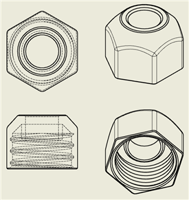
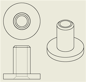
| Cable Nut | Cable Nut This part is used to tighten the cable in the connector so it can get pulled out. The design is pretty simple, one thing to not about this design, is that you need to either adjust or do some post process working on it if you wanna fit a larger cable through. Here is the technical drawing for this part.
The thread was made in the same way as for the other parts of this connector, just a trapezoid coiled cut, it has a slot on the inside for an O ring, but I found to be unnecessary since there is one underneath the mushroom which is the important one.
|
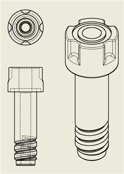
| Mushroom | Mushroom This is the last part needed for the connector, the mushroom. This is the smallest part and it's designed to be modified depending on the size of the cable you are planning to use. This is the only part on which I would recommend some glue. I'm personally not putting any, but I'm putting a smaller hole, and getting it wider by hand until I get a really really snug fit on the cable. For the most part I need this cable to be humidity resistant, but even without glue, if the the cable fits in snugly, it will be pretty water tight as well. The connector can accept cables up to 9mm, where at 9mm, you don't need this part at all. Here is the drawing for this part as well as how the 3D model looks like.
|
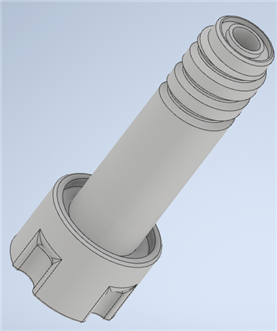

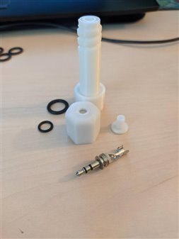
That would be all of the parts needed for that side of the connector. This side of the connector is same for both the 3.5mm jack as well as the barrel jack. I designed all of the parts so you can print them without using any supports, as for bed adhesion, you can go with a raft if you want to be sure you won't get an elephants foot at the bottom, or if you've dialed in your bed leveling, you can just go without it. Link to all of the STL files for 3D printing as well as STP files if you wish to edit the models yourself can be found on this link here: https://github.com/MilosRasic98/1MeterOfPi/tree/main/3D%20models/Waterproof%20Connector . Those files come without any warranty but you are free to do with them whatever you desire. If you do something cool with them please share them with me, I would love to see! Here is how this part of the build looks printed out.
3.5mm variant
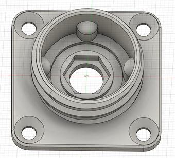
This is the part that will differ between the 3.5mm connector and the barrel jack connector. While it can work using only this connector for the cable mounted variant of the barrel jack, it just wasn't it. It was obvious that it was designed for it, even though it somehow fit. I did a few tweaks to make it work, but I will show that after going over this version of the connector first. Just like we did for all of the other parts, let's begin with a technical drawing of the part.
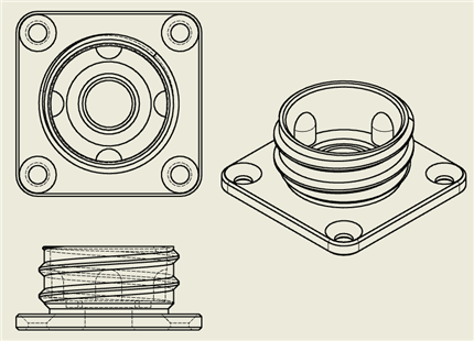
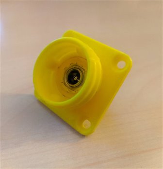
To mount it somewhere, I left holes big enough for M3 screws at each corner with a cone head, where the top of the cone on the model is 7mm in diameter. The thread of course matches the locking nut thread sot hey can work together, and you can also see the "key" that I talked about in the part about the body of the connector. Around the connector itself there is a small ring shaped channel left for an O ring to go in. This part is also designed with maximum overhangs of 45 degrees, so it can be printed out without any supports. As for the connector that goes inside it uses the standard 3.5mm female cable connector variant. Here is how it looks when it's printed.
Just like all of the other models, you can find 3D models for this link, both STL files and STP files on the GItHub link. On the picture you can see the 2 O rings used for this connector. The bigger one isn't that necessary, and you need to put in the connectors absolutely precisely for that one to have effect. Much more important is the small one inside the connector. To put it there I used a screwdriver and went in circles slowly, and then used a wider punch to just press it in firmly when it was inside all around.
Barrel jack variant (5.5/2.1mm)
While the above model can be used with a barrel jack connector, I had mixed success with it, because you need to use the barrel jack connector which is designed for a cable, of which I am not a big fan of. After trying to solder some thicker wires to it, the connector just melted inside itself and it had an internal short, that's why I did a redesign where in the same formfactor just using a different off the shelf connector, we can get much better results. Here is how that went, let's look at the changes on the model first.
Instead of a circular hole, you can now see a hexagonal hole going 2.4mm down. The reason for this is because I found barrel jack connectors which are designed to be mounted on a panel which come with a locking nut. This proved to a be a great thing, because with just a couple of small changes we can have a much better and sturdier connector. The normal ones requires a bit of super glue to hold in the connector properly, while this doesn't at all, but it still keeps the slot for the rubber O ring. Of course, to make it compatible with some of the things I've already designed for this project I kept the same outer form factor as the last one. Here is a picture of the printed version of this.
With that, the design process for these connectors is complete. Models for this one are available for free as well of course just like the rest on this link. With all of that complete, let's take a look at how these connectors used when cables are attached as well as when the panel mounted connectors are connected.
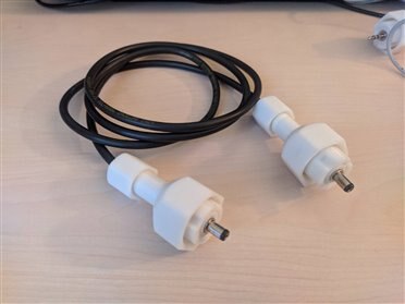
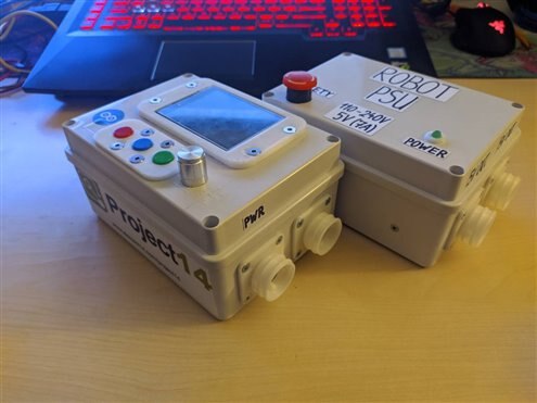
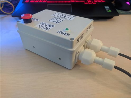
Finished Connector
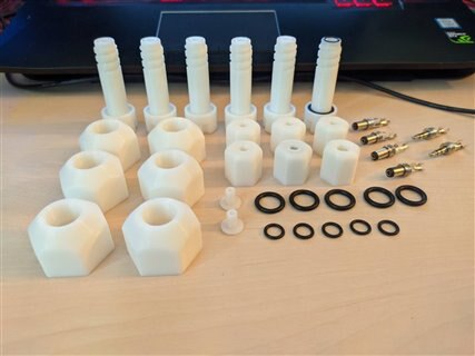
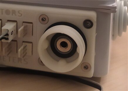
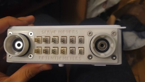
All of the pictures you're about to see are from my sensor kit for braccio project: Sensor Kit For BRACCIO . The robot, as mentioned before will be a part of the project as well. So here are some pictures of the cables I made for that project as well as the panel mounted connectors. These connectors will be present between all the different modules that will be found around my project. I may do a redesign and update if I manage to find a suitable 3.5mm female connector which is designed for panel mounting, as I have for the barrel jack. But until then, I will be staying with this design since it's working great.
3.Magnetic Connector
While the connectors I talked about will be used all around the project, this connector will be used only at one place, at the end of the robot arm. To explain my idea shortly for this project, I want this robot arm to go between 2 big pots where it can go and work on both of them. Because I want the arm to do multiple things I need multiple different tools at the top of the robot. One way to do this would be to have a rotating head with everything I need attached to it, but that would be too heavy and impractical. So, my idea is to design a quick release mechanism, where this robot could change the tool it's using, like a CNC would do, just not that precise and strong of course. Because I want some of the tools to have active components, like servos on the grippers and other tools, or sensors, I need a way to get power to that head as well as have a data line for sensors, or PWM line for servos. One way to do this would be to drag cables all over the project, but since the robot will be able to move about a meter, that would be a lot of cable to drag around which can catch on so many different stuff, another way is to have an energy source on every tool head, which isn't a good option either. So I went with the third option where I would have a connector on the robot which would go into the connector on the tool head.
Idea
Because I'm working with an arm that I can't be that precise with, the quick release mechanism will have to do the centering but It would be pretty difficult to just mount a connector on the side of the robot and call it a day. Let's say, for example, I wanted to use the 3.5mm jack again, it has the right number of pins, it's symmetrical, it has a lot of going for it, but, even if the robot is slightly off and the connector can't engage the whole quick release mechanism won't work. Even if it manages to center it properly, the tolerances for how far you need to push the connector in would be a big pain, it could maybe be done with some springs and stuff like that, but it's too complex. Instead of that, I had an idea to design a small connector using screws as terminals and screw heads as contacts, with both halves of the connectors having small but extremely strong 6.35x6.35mm magnets. If I have the magnets at the center of the connector, they would center the connector when engaging, and since those magnets are really strong they wouldn't let the connector disconnect due to vibrations and stuff like that. The robot would need to pull away for the connector to be disengaged. I will now show you how I designed the first working prototype, on which I'll base the final version. I can't do the final version yet, because it will heavily depend on the whole quick release mechanism, so I'll design those 2 at once for one of the next blogs but having this working prototype as the base for that. To design this part I used Fusion360.
Design
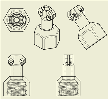
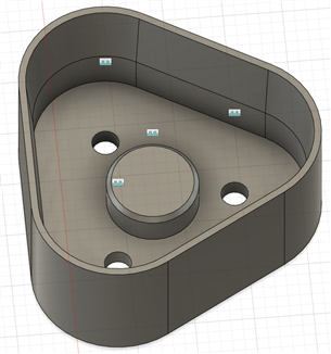
I kept the design really simple since this is just a proof of concept. As terminals and connection surfaces I used small M3 machine screws. To screw them in, I left a 2.4mm hole in the models and after that I went and cut the thread into the plastic. This is something I started doing recently and it's working out great honestly. The plastic is really easy for cutting threads. The connector has a triangular shape because of the 3 screws and magnet in the middle, any shape would work except a circle, because the magnet can't really orient the connector in that axis. Here are the 2 halves:
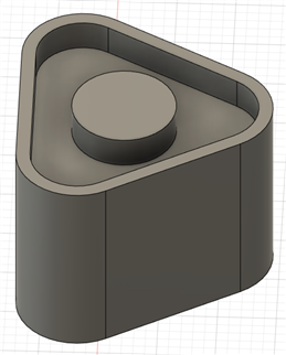
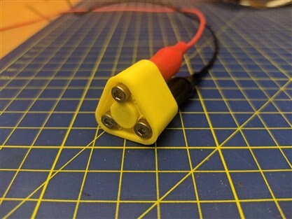
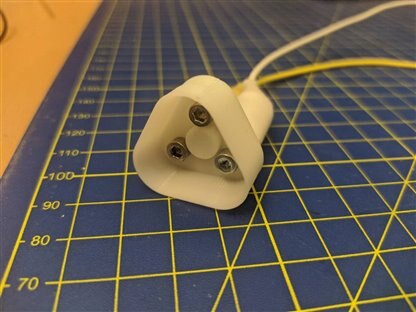
On the first picture is the part of the connector which will go onto the tool head, while on the second picture, the part of the connector that will be mounted on the robot. The main reason this design isn't finalized is because the connector which is mounted to the robot needs to move freely along one axis. If the connector is fixed on the robot and on the tool head there really isn't any point to the magnets. The best scenario for this design would be for the second part of the connector to be inside the shroud of the first part when the robot grabs a tool, because in that case the magnets can do their thing, and there is no chance of this connector falling out. But I'll talk more about that and show that once I finalize that design. For now, I printed this out in PLA, and hooked them up to a power supply and a small LED to test them out.
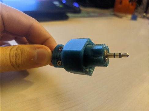
Finished Connector
After an hour or so of printing later I finished up with the first prototype. I won't be posting these files on GitHub since this is only a proof of concept, but I will post the final version for sure so everyone can download or use it in their own project if they find a place for it. To test out the connector I just used a small LED.
Here is a video of the connector working, you can see the magnets doing their thing and pulling the connector together, and not losing the connection even after some shaking. On the final design there will probably also be a spring pushing the connector into the other half, so there won't be any chance for the connector disconnecting unless the robot is changing tools.
In the second video we can see from how far the connector can actually pull itself together using the grid on my cutting mat. Those squares on the grid are 10mm x 10mm, so from the video, we can see it's pulling itself together at around 6-7mm, and that's looking at the outer plastic part, so the results is even better.
4. Conclusion
Looking at the requirements list from the start now, and going over it, we can see we have successfully finished all of the tasks up there. For the data and the power between modules we have the waterproof connectors and for the robot arm we have the magnetic connector. The design on the waterproof connector is final, with tweaks available for the length of the body of the connector and the size of the cable. The only thing I would possibly redesign at this point is the panel mount connector for the 3.5mm jack since it's using a cable connector, if I could find a panel mount connector that would mean I would completely erase the use of glue for these connectors. Another thing I I was thinking of trying maybe was to have to hole with a smaller diameter and heat up the connector with a lighter so it melts the plastic and it sets in like that.
For the magnetic connector, as I've already said, this is just the first working prototype, but I'm really happy with how it turned out and how it performs considering the small size of the magnets. I'll finalize the design when I finish up with the whole quick release mechanism which will come shortly, I'll post all of the files for it online then,
5. Fun news from the ISS
While I was working on this part of the project, something popped up in my feed about which I talked about in the last blog, so I thought why not put a short fun update section at the end of each blog if there are some news around it. The thing that popped up is that the astronauts aboard the ISS have harvested the first radishes that they were growing on the ISS inside the Advanced Plant Habitat-02. Here is the story!
6. What's next?
I wanted to write this blog to cover something that will show up in most of the blogs following up this one, the connectors. Next thing I will cover in my blogs is the Starter Kit that I received as one of the challengers, what's inside and what I'll be using through a short demo of that. While I'm working on that in the background the printer is hard at work making the test pieces for the quick release mechanism which I will hopefully finalize shortly. In the meantime I got some of the boards, sensors and modules I'll be needing for the project, while I'm, waiting for the others to arrive. Another thing that will come shortly is the mechanical build that will include the 2 big pots and the rail system as well as tests of the robot going up and down the rails! Hope I'll have all of that out shortly!
7. Summary
This was a simple design that will make it's way through a lot of my projects, not only this one, it's pretty easy to make and I found it's working really good for now. I'm aware it's not maybe as strong or heat resistant as off the shelf automotive grade connectors but it more than finishes the job I need it to do for my projects. In the future I may give it a go at trying to design a slim version of this connector, since it's pretty thick compared to the connector itself on the inside. All of the relevant links for this competition, link to the next and previous blog as well as my GitHub where I'm uploading all of the models can be found underneath. Thanks for reading the blog, hope you liked it and found it interesting!
Milos
Relevant links for the competition:
Link to my GitHub where you can find all of the files used for this project (code, 3D models,...):
Link to my Project Collection:
| Previous Blog | Next Blog |
|---|---|
| Project R.A.G. - Blog #1 - Mission Briefing | Project R.A.G. - Blog #3 - Lift Off |
Top Comments