


| Previous Blog |
|---|
| Project R.A.G. - Blog #8 - Mechanical Build P2 - Robot On Rails |
Blog #9 - Water & Rail Module
1. Introduction
Hi! This will be my ninth blog for the 1 Meter of Pi - Design Challenge. We're almost there, one more blog after this to hit 10! In the last blog I went over how I managed to fix the mechanics and electronics behind both of the movement systems present on the project. That being of course, the robot which had some surgery done to it and the rail system where I sorted out all of the electronics. You can find that blog linked at the top and at the bottom of this blog. In this blog, I will cover the last module I'll be making for this project, the Water & Rail module. I wanted to build a LAB Module as well, but due to the deadline being in just a few days, I won't have the time unfortunately. I will talk more about that module and the idea of it in my last blog which will wrap up the whole project. For now, let's take a look at the idea behind this module.
2. Idea & Plan
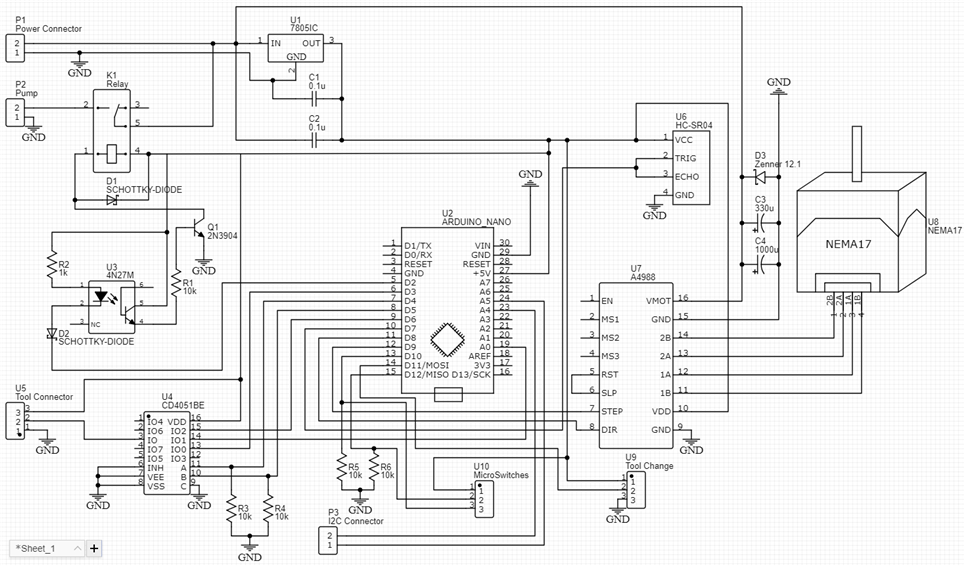
The diagram above explains everything I thought about for this module, but let's go step by step. Rather than having a single module for every little thing I decided to combine some of them. Now, in practice, this can be bad and good, on the one hand, we have fewer modules to worry about, on the other hand, if the module dies, it takes out a couple of system instead of just one. Let's see what I had envisioned for this module. Let's begin with the name, Water & Rail module. This module will take care of the second essential thing for our plants, and that is delivering water to them. To deliver water to them, I will use a small submersible 12V pump which I will turn on and off using a small relay which will a part of this module. The other word in the name is rail, this module will be controlling stepper motor which pushes the robot on the rails. If you're interested in that aspect of the project, you can check out the blog that is linked at the top and at the bottom of this one, where I went over everything about that subsystem. You can see outlined in green a HC-SR04 sensor as well, this will be used to measure how much we have left in our system for watering the plants. There is another critical functionality of this module that isn't in the name and that's playing with the tools on the robot. This module will control the servo in out Quick Tool Change Head which I covered in my fourth blog. Using a multiplexer, it will also communicate with all of the tools onboard the head over the magnetic connector that I covered in blog 2. Those would be all of the basic surrounding this module, we can now go and start designing the module part by part.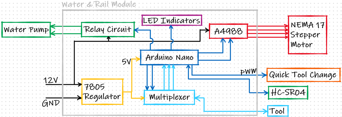
3. Design
There are 2 categories of designing we have to do for this module, the mechanical which is the enclosure and the electronics. I usually do the enclosure first and then the electronics, but this time, I decided to switch it up a bit. I will now go over the electronics, the design and the finished soldered perfboard and then cover everything about the enclosure.
Electronics
At the heart of the module will be an Arduino Nano as in rest of my modules. The size, price and the number of pins just make it a perfect candidate for this. The Nano will be surrounded by multiple subsystems which I will cover now one by one and the full schematic in the end will a combination of all of this subsystems made into a single schematic. Let's begin with the watering side, the relay circuit and the HC-SR04.
Relay circuit
As I've already talked about my Idea & Plan section, I want to use a small relay to turn on/off the power of a small 12V submersible pump for watering the plants. I could have just used an off the shelf module, but I want everything to be soldered to a single perfboard. I will be of course using a small 5V relay for this, but it's not as simple as just connecting the relay coil to one of the pins on the Arduino. Playing with relays is something I covered in my Braccio Sensor Kit blog and also touched upon in my seventh blog for this competition. We need a bit more circuitry for using the relay safely without damaging the Arduino. A simple example is a flyback diode on the relay. Here is what we can expect if we don't use one.

On the second, green, channel we can see a huge spike playing with the relay. This spike can absolutely kill our Arduino, specially if we're turning the relay on/off multiple times. A simple solution for that is adding a flyback diode, I used a Schottky diode for this purpose, and here is how it looks when we use that.
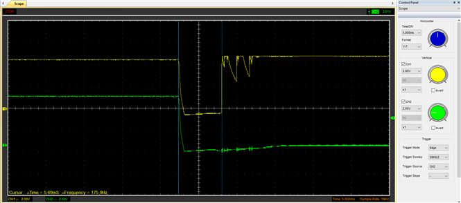
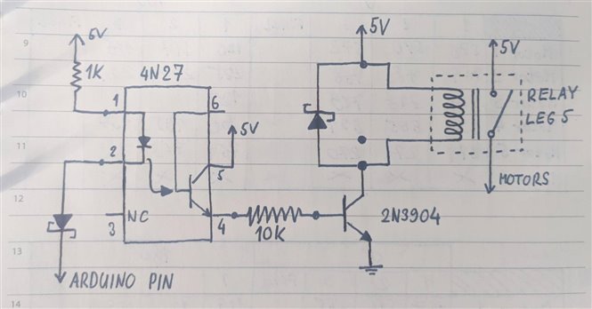
You can see that now, when we're powering down the relay, we're not getting a huge spike which can kill our Arduino. But that's just one part of the relay circuit, we also need to limit the current that the Arduino pin will have, since that can also damage the Arduino, another good thing would be to isolate one from another using an optocoupler. In the end, considering all of this, we end up with a circuit looking like this.
Circuit
Test
This is the same circuit I used for the robot arm, so I know it is functioning properly. Here is a short video I filmed back then of testing out this circuit to make sure it works as planned. The only thing to watch out here for is that we need to pull the output of the pin LOW to actually turn on the relay.
3 pin HC-SR04
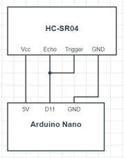
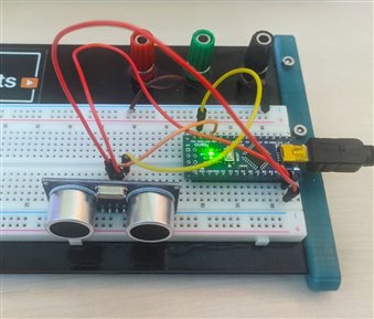
Now it's time to take a loot at the HC-SR04 ultrasound sensor. I think it can safely be said that this is the most popular sensor out there and for a reason. We're actually measuring something physical and getting pretty good data and it's really easy to use. The connector is designed use 3.5mm jacks and it's much easier for me to use something with 3 pins rather than 4 pins. A friend was doing some work with these sensors and mentioned to be a 3 wire mode for them so I wanted to check it out. Simply put, instead of using 4 wires, 5V, GND, Echo & Trigger, we would use 3 pins, 5V, GND and Data, where the echo and trigger pins are connected as a single pin. We can do this because those pins are never used at the same time. This is something I haven't considered trying, but just connecting the pins together and using NewPing library, everything worked great.
Circuit
I've seen some people connect the pins together using a resistor but I just connected the 2 together and got great results. The wiring is exactly the same as you expect on a standard sensor, just with both the Echo & Trigger pins being attached to the same digital pin on the Arduino.
Code
As for the code, I just used the example from the New Ping library that I've linked above. The library is extremely easy to use with one line needed for reading the sensor data. The only thing I changed from the example code is that I've defined both of the pins to be pin 11. The example in question can be found under Examples --- NewPing --- NewPingExample.
// ---------------------------------------------------------------------------
// Example NewPing library sketch that does a ping about 20 times per second.
// ---------------------------------------------------------------------------


#include <NewPing.h>


#define TRIGGER_PIN  11  // Arduino pin tied to trigger pin on the ultrasonic sensor.
#define ECHO_PIN     11  // Arduino pin tied to echo pin on the ultrasonic sensor.
#define MAX_DISTANCE 200 // Maximum distance we want to ping for (in centimeters). Maximum sensor distance is rated at 400-500cm.


NewPing sonar(TRIGGER_PIN, ECHO_PIN, MAX_DISTANCE); // NewPing setup of pins and maximum distance.


void setup() {
  Serial.begin(9600); // Open serial monitor at 115200 baud to see ping results.
}


void loop() {
  delay(200);                     // Wait 50ms between pings (about 20 pings/sec). 29ms should be the shortest delay between pings.
  Serial.print("Ping: ");
  Serial.print(sonar.ping_cm()); // Send ping, get distance in cm and print result (0 = outside set distance range)
  Serial.println("cm");
}
Test
After connecting everything and uploading the code to the Arduino, here are my test results. Everything worked great, the only bug it seemed to have is that it wouldn't detect the range sometimes and just display 0cm distance, so to fix that, I'll just make sure to not use values which are either 0cm or extremely high, since those will indicate that it was a bad read on the sensor side. My idea for this sensor is for it to be above the surface of the liquid and measure the distance between the sensor and the liquid, in that way, I will get how high the water level is in my container without using any contact or mechanical sensors.

Motor driver circuit
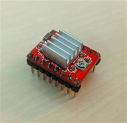
This part of the circuit I covered in detail in my last blog: Project R.A.G. - Blog #8 - Mechanical Build P2 - Robot On Rails . There, I talked about what is necessary to do to protect both the motor driver and the driver from frying up. I've fried up 2 of the DRV8825 drivers because I didn't protect them while using them. If you're interested in more detail, check out that blog, here, I'll just show the final circuit that I will be using which will surround the driver itself.
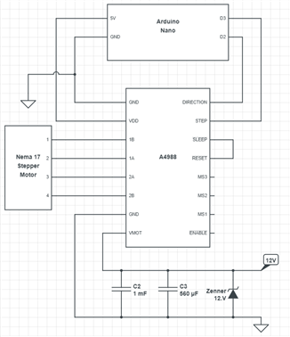
Essentially, what you need to protect the driver are capacitors at the input, but a Zenner diode proved to be a great addition as well. Another thing to be careful of is turning the motor by hand a lot and fast, that can kill the driver easily and get it to pretty high temperatures, over 100C. But this circuit above proved to work great for me.
Multiplexer circuit
This is in my opinion the most interesting part of this module, the multiplexer circuit. I'll first begin by explaining my idea for using a MUX for this use case and go over what I'm going to use and how I'm going to use it. Let's first take a look at a zoomed in picture of the diagram, where the MUX is.

Circuit
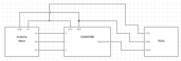
We can see here that the MUX is a connection between the Arduino Nano and the tool on our robot. If we go back to my fourth blog where I covered the quick tool change mechanism, the idea was for the robot to have multiple different tools which can be anything from grippers, sensors, camera holders and so on. The part where the MUX comes in handy is when I want to do all of that using just one connector. Using a multiplexer allows me to choose to where I want to route the tool signal. I might want to route it to an analog pin and read the value from that, I might want to route it to a PWM pin so I can control a servo, or maybe an interrupt pin so I can trigger and even when the tool on the robot detects something and so on. Here is a schematic explaining what I mean.
CD4051BECD4051BE
The multiplexer I will be using is a CD4051BECD4051BE from Texas Instruments, it's an Analog Multiplexer/Demultiplexer which will be perfect for our application. I've had prior experience with them and they worked great. One thing to be wary off when using them is to tie the selector pins to ground if you're not using them. More info on this part and the datasheet can be found on these links:
- https://export.farnell.com/texas-instruments/cd4051be/multiplexer-8-channel-16dip/dp/3124932?st=CD4051BE
- https://www.ti.com/store/ti/en/p/product/?p=CD4053BE
There are a few variants of this chip with the CD4052BECD4052BE and CD4053BECD4053BE with the differences being they have a couple of smaller multiplexers onboard, while the CD4051BECD4051BE comes with 1 8 channel multiplexer. I will be using the CD4051BECD4051BE. I will now go through the pinout of this chip and make a small test to showcase the functionality of this multiplexer.
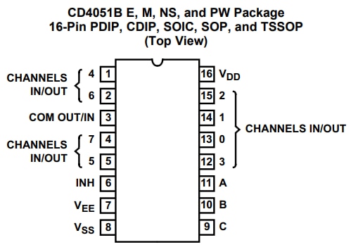
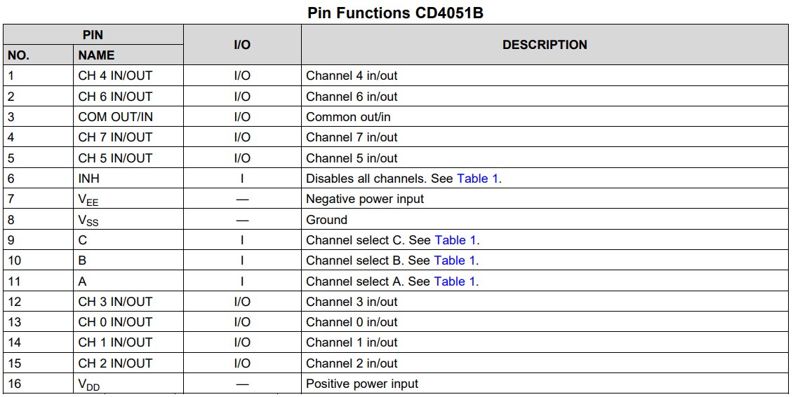
The datasheet is great with really clear instructions. Here we can see the pinout of the chip and the function of all of the pins. Let's take a look at how to use this pin by pin. We have the power supply pins first, the chip can go up to 20V but I will be using it at 5V, I will be using it by connecting Vdd to 5V, Vee & Vss to GND. With the pins A,B & C we can select which one of the 0-8 channels will be connected to the COM OUT/IN. The table of what is the least significant bit in this case can also be found in the datasheet.
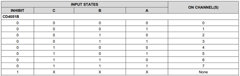
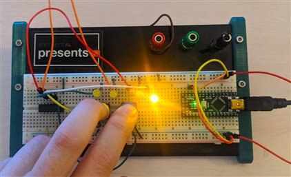
As you can see from the table, the least significant bit is A, followed by B and then finally by C. INH pin on the chip is used to disable all of the channels and we should connect it to ground when soldering it to our perfboard. To showcase the functionality of this chip, I'll just connect this multiplexer with a couple of LED-s with 5V at the COM IN/OUT pin to show how we can turn on/off 8 LED-s using only 3 inputs.
Test circuit
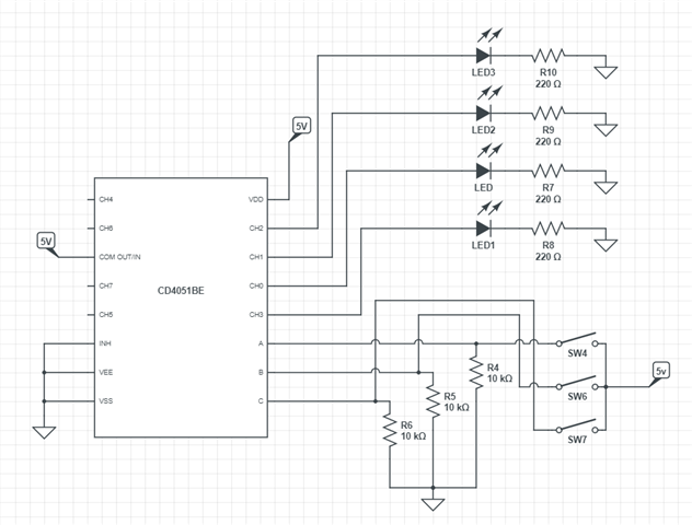
On the picture above you can see how everything should be connected. The LED-s above are connected only to the first 4 channels, so we can get away by using only the least 2 significant bits, the A & B. Though, as I've mentioned above, you should then connect C to the ground, that's why you can see I have a pull down resistor on all of the switches. I'll now wire this up and show you a short demonstration for this.
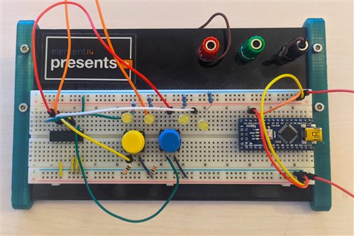
In this picture, you can see everything connected like on the schematic above, except the C input on the multiplexer which I tied to ground since I'm only working with 4 LED-s. The Arduino is on the perfboard because I will be using it as a 5V power source for this demonstration.
Test
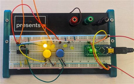
On the pictures above we can see the first 2 states. If nothing is pressed we will have the channel zero active - connected to our COM IN/OUT which is connected to 5V which is why are first LED is shining. If we press the first button, we can see the second LED light up, that is channel 1.
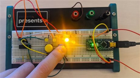
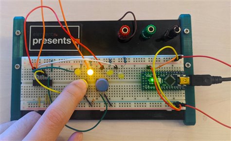
On these 2 pictures we can see the last 2 states. When only the second button is pressed we have the third LED shining, and when we press both buttons at the same time we have the fourth LED shining. It's a really simple concept which can be used and is used often to save a lot of pins. While I know that a lot of people have played around with this already, I thought it would be a good idea to share a small demonstration like this on how to use something like this, because it's really easy to use and you can get a lot of good results. Here is a short video for this test.
That would be all about this part of the circuit. You can now see how I plan on using this in my project. The COM IN/PUT pin will be connected to the connector that goes to the tool on the robot, while the CH0, CH1, CH2 pins for example are connected to an interrupt pin, PWM capable pin and an analog pin. Then I just connect A & B to 2 random digital pins and I can control like that to what the tool is connected.
Full schematic
And here is the full schematic for this module. You can see that it's made out of smaller parts that we have covered in this blog. The only thing left to do is turn on the soldering iron and get to work. There's not too many components, but I'll try going slowly nevertheless to avoid any additional work on the board if possible.
Soldering the perfboard
Here are the pin connections for the Arduino, I've chosen them mostly on the features of the pins, for example, I've connected the limit switches to interrupt pins so I can have an interrupt procedure to work as soon as one of those switches is activated, or the pins on which a servo will be attached had to be PWM and so on.
| # | Arduino Pin | Special Feature | Connected to |
|---|---|---|---|
1 | D2 | Interrupt | Microswitch 1 |
| 2 | D3 | PWM, Interrupt | Microswitch 2 |
| 3 | D4 | Pump relay | |
| 4 | D5 | PWM | Tool change servo |
| 5 | D6 | PWM | Tool 1 - Servo - Mux channel 0 |
| 6 | D7 | Mux A | |
| 7 | D8 | Mux B | |
| 8 | D9 | PWM | STEP |
| 9 | D10 | PWM | DIRECTION |
| 10 | D11 | PWM | HC-SR04 |
| 11 | D12 | Tool - digital input - Mux channel 2 | |
| 12 | A0 | Tool - Sensor - Mux channel 1 | |
| 13 | A4 | SDA | SDA |
| 14 | A5 | SCL | SCL |
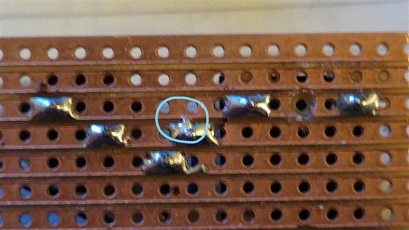
After a couple of hours of soldering, I've ended up with this board. The board with the lines underneath instead of just dots makes my life so much easier for soldering, but even easier would have been to just design a PCB rather than trace everything wire by wire. The result still ended up looking good.
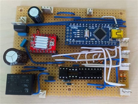
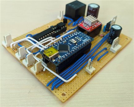
We have 8 connectors in total on the board, I went again with the nylon connectors since they are really easy to crimp and make a really easy way to connect the board to the connectors inside the enclosure. The board did have a couple of faults that I had to fix, like where I miscounted the pins on the multiplexer, or just completely forgot to connect the stepper motor to the driver and then wonder why the motor isn't spinning. Besides those there were 2 such awful little shorts, but I managed to find them by sheer luck.
Enclosure
For the enclosure I went with another off the shelf electronics box, this one is the same one I used for the 12V power supply, it's a 150x110x70mm box. The only thing the box is missing of course is 3D printed connectors like the rest of the modules already have. As you can see from the board above, I need 8 connectors, but there's one that's is different from the others. While I managed to reduce the number of pins needed for the HC-SR04 sensor from 4 to 3, I can't do that on the Stepper. So I have 2 options. Use 2 connectors for the motor, or design a new connector using the 4 pin 3.5mm female jack which is made for soldering onto a board. I will try the latter and if it fails, I can always go back to the first option.
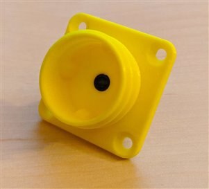
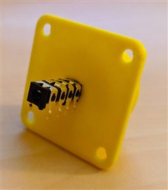
4 pin 3D printed connector
And here is another addition to the collection of 3D printed connecters I am using for this project. Until now, I've designed the 3.5mm one, barrel jack one, and USB one. This time, it will be another 3.5mm connector, but this time, with 4 pins instead of the usual 3. I couldn't find a female 3.5mm connector which is supposed to be panel mounted anywhere near me, but as soon as I do I will do another redesign, since the redesign with the barrel jack works so much better since no glue is needed and it's a pure mechanical bond. Let's get into the design for this connector.
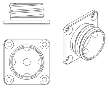

To design these, I used Fusion360 and for printing I used my Ender 3 Pro. To print them out I used standard quality settings sliced with Cura 4.6 at 0.2mm layer height using a 0.4mm nozzle. As for temperatures, nozzle at 205C and bed at 60C and printed using Creality Yellow PLA. You can find the models for this connector both in STP and STL form as well as all other of my models on the GitHub repository dedicated for this project. Here is a link for the folder where you can find the 3D models for this and other connectors: 3D printed locking connector - Models. You are free to do with these models whatever you want, so enjoy!
Besides this connector, I needed 7 more connectors for this project, 5 of them being the 3.5mm variant and 2 more of the barrel jack variant. In the end, the enclosure ended up looking like this.
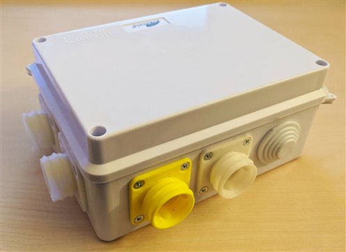
I am missing a few of the actual connectors that go inside my printed ones, so I won't be connecting and soldering all of them now until I get those connectors. Until then, this module is finished, so let's play around a bit with it and do some testing with it to see what it can do. Of course, that means, we need a bit of code to do that, so let's start with that.
4. Software
This won't be the final code of course, but it will about 90% there. This code will test out all of the functionality of this module except the I2C inter module communication. We have a couple of things to test:
- Seeing the robot move on the rails
- Seeing the end stop switches working
- Water pump working
- Tool change and tool working
To begin with the code, let's just take a look at the libraries I'll be using for this code. There will 2 of them in total, one being the standard Arduino Servo library for controlling the servo motors and the other being the NewPing library about which I talked above in the blog which is used for the HC-SR04 sensor. Let's take a look at the code now:
/*
 *                                                  Water & Rail Module
 *
 * ___________________________________________________________________________________________________________________
 * This code is for the Water & Rail module featured in my project for 1 Meter of Pi design challenge on element14.com
 * You are free to do with this code whatever you want!
 * ___________________________________________________________________________________________________________________
 *
 */


//  Libraries
  #include <NewPing.h>
  #include <Servo.h>


//  Pins
  #define Pin_MSwitch1 2
  #define Pin_MSwitch2 3
  #define Pin_Pump 4
  #define Pin_ToolChange 5
  #define Pin_ServoTool 6
  #define Pin_MuxA 7
  #define Pin_MuxB 8
  #define Pin_Step 9
  #define Pin_Direction 10
  #define Pin_HCSR04 11
  #define Pin_ToolInput 12
  #define Pin_ToolSensor A0
  #define Max_Distance 200


//  Setting up the HC-SR04
  NewPing WaterLevelSensor(Pin_HCSR04, Pin_HCSR04, Max_Distance);


// Setting up the servo motors
  Servo toolChangeServo;
  Servo toolServo;


//  Constants
  int containerDepth = 30; // This constant defines how deep our water storage container is, the measuremnt is in cm
  double containerSurface = 25; // The surface area of the container in cm^2
  int stepperDelay = 1000;  // This delay determines the speed of our stepper motor


//  Variables
  volatile bool limitSwitch1 = false; // This variable is for the first of the 2 limit switches on the rail
  volatile bool limitSwitch2 = false; // This variable is for the second of the 2 limit switches on the rail
  int muxA = 0;
  int muxB = 0;
  int selectedTool = 0;


/*
 *
 *  FUNCTIONS
 *
 */


//  Function for calculating how much water is left in the sytem
double LiquidLevel(){

    int sensorReading = 0;
    double liquidLevel = 0;
    double sensorData = 0;
    int i = 0;

    while(i < 3){
        sensorReading = WaterLevelSensor.ping_cm();
        if(sensorReading > 0 && sensorReading <= containerDepth){
            sensorData += sensorReading;
            i++;
          }
        delay(50);
      }

    sensorData = sensorData/3;
    liquidLevel = (containerDepth - sensorData)*containerSurface;
    liquidLevel = liquidLevel/1000; //  Converting the value to L

    Serial.print("Current volume of water in the container is: ");
    Serial.print(liquidLevel);
    Serial.println("L");

    return liquidLevel;
  }


// Function for turning on and off the water pump
void TurnPump(String s){
    if(s == "on" || s == "ON" || s == "1" || s == "On"){
        digitalWrite(Pin_Pump, LOW);
      }
      else if(s == "off" || s == "OFF" || s == "0" || s == "Off"){
          digitalWrite(Pin_Pump, HIGH);
        }
  }


// Function for giving plants a set amount of water
void WaterPlants(double volume){
    double startVolume = LiquidLevel();
    if(volume > startVolume){
        Serial.println("Not enough water");
      }
      else{
          double endVolume = startVolume - volume;
          while(LiquidLevel() >= endVolume){
              TurnPump("On");
            }
            TurnPump("Off");
            Serial.print("Water left for watering the plants is: ");
            Serial.print(LiquidLevel());
            Serial.println("L.");
        }
  }


//  Interrupt Pin Function 1
void LimitSwitch1On(){
    limitSwitch1 = true;
    Serial.println(1);
  }


//  Interrupt Pin Function 2
void LimitSwitch2On(){
    limitSwitch2 = true;
    Serial.println(2);
  }


//  Interrupt Pin Function 3
void LimitSwitch1Off(){
    limitSwitch1 = false;
    Serial.println(3);
  }


//  Interrupt Pin Function 4
void LimitSwitch2Off(){
    limitSwitch2 = false;
    Serial.println(4);
  }


// Function for moving the robot on rails
void MoveRobot(int dir, int numberOfSteps){


    if(dir == 0 || dir == 1){
      digitalWrite(Pin_Direction, dir);
      }
      else{
          return;
        }


    for(int i = 0; i < numberOfSteps; i++){


      if((dir == 0 && limitSwitch1 == false)||(dir == 1 && limitSwitch2 == false))
        digitalWrite(Pin_Step, HIGH);
        delayMicroseconds(stepperDelay);
        digitalWrite(Pin_Step, LOW);
        delayMicroseconds(stepperDelay);
      }

  }


//  Function for moving the robot until he reaches one end
void MoveRobotToStart(){
    digitalWrite(Pin_Direction, 0);
    bool continueLoop = true;
    while(continueLoop == true){
        if(digitalRead(Pin_MSwitch1) == 0){
            digitalWrite(Pin_Step, HIGH);
            delayMicroseconds(stepperDelay);
            digitalWrite(Pin_Step, LOW);
            delayMicroseconds(stepperDelay);
          }
          else{
              continueLoop = false;
              Serial.println("Limit switch 1 activated");
            }
      }
  }


//  Function for moving the robot until he reaches the other end
void MoveRobotToEnd(){
    digitalWrite(Pin_Direction, 1);
    bool continueLoop = true;
    while(continueLoop == true){
        if(digitalRead(Pin_MSwitch2) == 0){
            digitalWrite(Pin_Step, HIGH);
            delayMicroseconds(stepperDelay);
            digitalWrite(Pin_Step, LOW);
            delayMicroseconds(stepperDelay);
          }
          else{
              continueLoop = false;
              Serial.println("Limit switch 2 activated");
            }
      }
  }


//  These functions are for using the ToolChange servo on the robot
void TakeTool(){
    toolChangeServo.write(0);
  }

void ReleaseTool(){
    toolChangeServo.write(180);
  }


// Function playing with the tool on the robot
void ChangeToTool(int toolNumber){
    switch(toolNumber){
        case 0:
          muxA = 0;
          muxB = 0;
          Serial.println("You have chosen the Servo tool.");
          break;
        case 1:
          muxA = 1;
          muxB = 0;
          Serial.println("You have chosen the Sensor tool.");
          break;
        case 2:
          muxA = 0;
          muxB = 1;
          Serial.println("You have chosen the Input tool.");
          break;
        case 3:
          muxA = 1;
          muxB = 1;
          Serial.println("You have chosen an undefined tool.");
        default:
          Serial.println("Error: Tool index out of range!");
      }
    if(toolNumber >= 0 && toolNumber <=3){
        selectedTool = toolNumber;
        digitalWrite(Pin_MuxA, muxA);
        digitalWrite(Pin_MuxB, muxB);
      }
  }


void ServoTool(int angle){
    if(selectedTool == 0){
      if(angle >= 0 && angle <= 180){
        toolServo.write(angle);
        }
        else{
            return;
          }
      }
      else{
          Serial.print("You have not chosen this tool, the tool which is selected currently is number ");
          Serial.print(selectedTool);
          Serial.println(". In order to use this tool, you must select tool 0 first");
        }
    }


int SensorTool(){
    if(selectedTool == 1){
        return analogRead(Pin_ToolSensor);
      }
      else{
          Serial.print("You have not chosen this tool, the tool which is selected currently is number ");
          Serial.print(selectedTool);
          Serial.println(". In order to use this tool, you must select tool 1 first");
        }
  }


int InputTool(){
    if(selectedTool == 2){
        return digitalRead(Pin_ToolInput);
      }
      else{
          Serial.print("You have not chosen this tool, the tool which is selected currently is number ");
          Serial.print(selectedTool);
          Serial.println(". In order to use this tool, you must select tool 2 first");
        }
  }


/*
 *  START OF OUR PROGRAM
 */


void setup() {


  //  Starting up Serial at 9600 baud rate
    Serial.begin(9600);


  //  Setting up all of the pins
    pinMode(Pin_MSwitch1, INPUT);
    pinMode(Pin_MSwitch2, INPUT);
    pinMode(Pin_Pump, OUTPUT);
    pinMode(Pin_MuxA, OUTPUT);
    pinMode(Pin_MuxB, OUTPUT);
    pinMode(Pin_Step, OUTPUT);
    pinMode(Pin_Direction, OUTPUT);
    pinMode(Pin_ToolSensor, INPUT);


  //  Setting up interrupts for the MicroSwitch pins
    attachInterrupt(digitalPinToInterrupt(Pin_MSwitch1), LimitSwitch1On, RISING);
    attachInterrupt(digitalPinToInterrupt(Pin_MSwitch2), LimitSwitch2On, RISING);
    attachInterrupt(digitalPinToInterrupt(Pin_MSwitch1), LimitSwitch1Off, FALLING);
    attachInterrupt(digitalPinToInterrupt(Pin_MSwitch2), LimitSwitch2Off, FALLING);


  // Making sure the pump is turned off when starting the module
    TurnPump("Off");


  // Attaching servos to their deisgnated pins
    toolChangeServo.attach(Pin_ToolChange);
    toolServo.attach(Pin_ServoTool);
    delay(10000);
}


// Test function
void Bounce(){
    for(int i = 0; i < 2; i++){
        MoveRobotToStart();
        delay(200);
        MoveRobotToEnd();
        delay(200);
      }
  }


void loop() {
  Bounce();
  TurnPump("On");
  delay(15000);
  TurnPump("Off");
  delay(3000);
  TurnPump("On");
  delay(15000);
  TurnPump("Off");
  Bounce();
  TakeTool();
  delay(500);
  ReleaseTool();
  delay(500);
  TakeTool();
  delay(500);
  ServoTool(180);
  delay(500);
  ServoTool(0);
  delay(500);
  ServoTool(180);
  delay(500);
  ServoTool(0);
  delay(500);

}
The code consists of mostly function that I've written which are designed to do different things, from turning on/off the pump, to homing the robot on the rails. There will be more function added than this in the future which will take into account I2C communication, another thing I want to do is convert the stepper steps into cm which is done easily enough. Main programming and control part will be done by the Raspberry, the point of the Arduino in the module is to listen to the commands from the Raspberry and execute them. With the code done, let's get to the fun part!
5. Testing the module
As I've already mentioned above, there are a couple of things I want to test out to know that everything is working as supposed to. I will show the 4 tests I conducted, the first one being to see if the servos are moving as they should, where one is getting it's data over the multiplexer, the second test will be activating the pump over our relay circuit, the third test will be letting are astronaut going from one end of rails to the other and finally combining all of those at once. These will be simple sequential tasks, but using a timer can go a long way with this module if needed.
1. Test --- Servo & servo over multiplexer
2. Test --- Water pump
3. Test --- End to end on rails
4. Test --- Combined test
6. What's next?
With the last module finished, all that's left now is to connect everything together and build the rest of the structure. When I say connect everything together, there are 2 things I am talking about, one being print out a lot of the locking connectors for the cables and solder everything and another being program everything to work in unity. My next blog will cover the finishing mechanical build, where I will be mounting the structure that will go above the robot and rails and have the LED lights mounted to it for illuminating the plants. When it's out, the next blog will be linked at the bottom of this blog.
7. Fun news from the ISS
In this segment fun news from the ISS, while I didn't find any more recent news than the radish harvest 2 which I covered in the last blog, I found a cool timelapse of those radishes growing onboard the ISS. You can check out the video below!
8. Summary
Another module wrapped up and 1 more blog to hit 10 blogs! Everything works as expected and I'm pleased with that, it's a good thing that I've done the research and fixes on the stepper driver prior to making this module, because I don't have to go and modify this module a lot. As of writing this blog, there are only a couple of days left until the deadline, so, once again, off to the races to makes this work! All of the relevant links for this competition, link to the next and previous blog as well as my GitHub where I'm uploading all of the models can be found underneath. Thanks for reading the blog, hope you liked it and found it interesting!
Milos
Relevant links for the competition:
Link to my GitHub where you can find all of the files used for this project (code, 3D models,...):
Link to my Project Collection:
| Previous Blog | Next Blog |
|---|---|
| Project R.A.G. - Blog #8 - Mechanical Build P2 - Robot On Rails | Project R.A.G. - Blog #10 - Mechanical Build P3 (Final) |
Top Comments
-

DAB
-
Cancel
-
Vote Up
+2
Vote Down
-
-
Sign in to reply
-
More
-
Cancel
-

milosrasic98
in reply to DAB
-
Cancel
-
Vote Up
+1
Vote Down
-
-
Sign in to reply
-
More
-
Cancel
Comment-

milosrasic98
in reply to DAB
-
Cancel
-
Vote Up
+1
Vote Down
-
-
Sign in to reply
-
More
-
Cancel
Children