


#2 The Mechanism of IPC semaphore
Table of Contents
1 Rocking the IPC@the Core
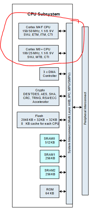
Themes of At the Core challenge is pushing the limits of Dual Core on the PSoCTm 62S4, to take advantage of the dual core architecture of the PSoC 62 microcontroller. Here is the CPU subsystem with Cortex-M0+ core and Cortex-M4 core.
Inter-processor communication (IPC) provides the functionality for multiple processors to communicate and synchronize their activities. IPC hardware is implemented using two register structures.This allows for building varying models of interface,
■ IPC Channel: Communication and synchronization between processors is achieved using this structure.
■ IPC Interrupt: Each interrupt structure configures an interrupt line, which can be triggered by a ‘notify’ or ‘release’ event of any IPC channel.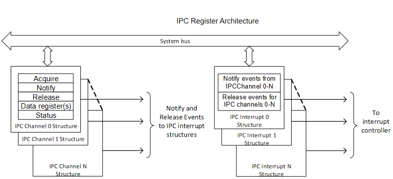
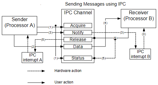
To make it simplified, to understand IPC, one can take IPC channel as kind of LOCK. The IPC channels can be used to implement locks for some form of mutually exclusive access to a shared resource. When multiple processors share a resource, the processors are capable of acquiring and releasing the IPC channel. So the processor can assume an IPC channel as a lock. This IPC mechanism can avoid confict on resource access.
For PSoC 62S4, the shared resource is accessible by two 32-bit register IPC_STRUCTx_DATA0 and IPC_STRUCTx_DATA1. These registers can be considered as the shared data memory for the channel. Typically, these registers will hold messages that need to be communicated between processors. If the messages are larger than the combined 64-bit size, place pointers in one or both of these registers. It takes some time to understand every details in graph below,
With all the reference files list below, one can get full picture. But just remember, the IPC channel is one LOCK to shared Memery for M0+ core and M4 core to access safely. And Infineon’s ModusToolbox 3.0 is just the perfect software development platform.
2 ModusToolbox 3.0 for IPC project
In addition to Modus Toolbox, PSoC creator is alternative choice for IPC project.
But PSoC 62S4 is not supported for now. So use Modus Toolbox IDE instead,
3 WorkFlow for PSoC 62S4 dual-core IPC Project
3.1 Startup sequence
After device reset, only CM0+ executes; CM4 is held in a reset state. CM0+ first executes Infineon system and security code. After CM0+ executes the system and security code, it executes the application code. In the application code, CM0+ may release the CM4 reset, causing CM4 to start executing its application code.
3.2 Create a dual-core application
- Create new application based on an existing dual-CPU code example. Use any code example with a repo name that includes “dual-CPU” as a start point. For most cases, the mtb-example-psoc6-dual-cpu- empty-app is a good choice. That is easy to start but it takes more time to debugg.
- Or convert single-core application to a dual-core application.
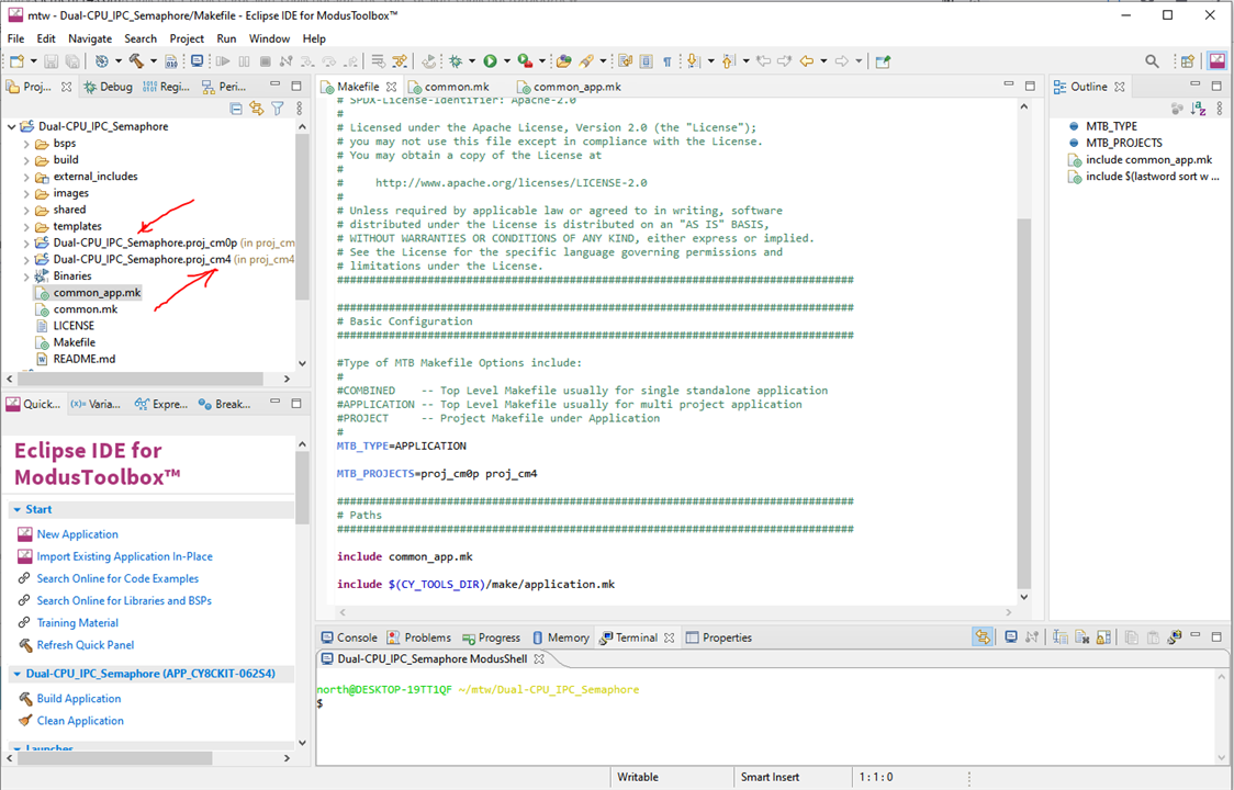
Change Makefile variables – Open the Makefile of the application and modify the variables. The common.mk and common_app.mk Makefiles at the root level of the dual-core application shall be modified as well such as MTB_TYPE, APPNAME, COMPONENTS, and DISABLE_COMPONENTS and add new values for variables such as COMPONENTS and DISABLE_COMPONENTS.
Customizing linker scripts - The CM0+ and CM4 projects each have their own linker scripts supplied by the BSP. By default, the CM0+ CPU consumes only 8192 [0x2000] bytes of flash and 8192 [0x2000] bytes of SRAM. If CM0+ project requiresmore memory, both linker scripts require changes.The CM0+ linker script is located at directory - bsps/TARGET_APP_<BSP_NAME>/COMPONENT_CM0P.
Sharing libraries and peripherals - The deps folder of each project contains the list of libraries used by that project. As described earlier ModusToolbox use Library Manager to manage BSP and libraries.
Create source files - Coding for the customized project. Balance performance and low power status.
4 Create IPC Semapore Project
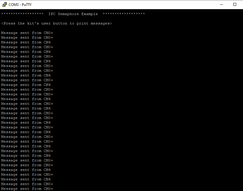
The sample project share the UART hardware block to send messages to the computer. An IPC semaphore controls access to the UART to avoid situations where both CPUs attempt to send messages at the same time. The same IPC semaphore is also used to synchronize the initialization code between the two CPUs. The example provides an option to disable semaphore usage to observe how it affects the system. An LED on the kit indicates whether the semaphore is being used.
The main code in M0+ core,
int main(void)
{
    cy_rslt_t result;

    /* Initialize the device and board peripherals */
    result = cybsp_init() ;
    if (result != CY_RSLT_SUCCESS)
    {
        CY_ASSERT(0);
    }
    /* Enable global interrupts */
    __enable_irq();

    /* Lock the sempahore to wait for CM4 to be init */
    Cy_IPC_Sema_Set(SEMA_NUM, false);

    /* Enable CM4. CY_CORTEX_M4_APPL_ADDR must be updated if CM4 memory layout is changed. */
    Cy_SysEnableCM4(CY_CORTEX_M4_APPL_ADDR);

    /* Wait till CM4 unlocks the semaphore */
    do
    {
        __WFE();
    }
    while (Cy_IPC_Sema_Status(SEMA_NUM) == CY_IPC_SEMA_STATUS_LOCKED);

    /* Update clock settings */
    SystemCoreClockUpdate();

    for (;;)
    {
        /* Check if the button is pressed */
        if (Cy_GPIO_Read(CYBSP_SW2_PORT, CYBSP_SW2_PIN) == 0)
        {
        #if ENABLE_SEMA
            if (Cy_IPC_Sema_Set(SEMA_NUM, false) == CY_IPC_SEMA_SUCCESS)
        #endif
            {
                /* Print a message to the console */
                Cy_SCB_UART_PutString(CYBSP_UART_HW, "Message sent from CM0+\r\n");

            #if ENABLE_SEMA
                while (CY_IPC_SEMA_SUCCESS != Cy_IPC_Sema_Clear(SEMA_NUM, false));
            #endif
            }
        }
    }
}
The main code in M4 core,
int main(void)
{
    cy_rslt_t result = CY_RSLT_SUCCESS;

    /* Initialize the device and board peripherals */
    result = cybsp_init();
    if (result != CY_RSLT_SUCCESS)
    {
        CY_ASSERT(0);
    }

    /* Enable global interrupts */
    __enable_irq();

    /* Free the hardware instance object iff initialized by other core
     * before initializing the same hardware instance object in this core. */
    cyhal_hwmgr_free(&CYBSP_UART_obj);
    cyhal_hwmgr_free(&CYBSP_DEBUG_UART_RX_obj);
    cyhal_hwmgr_free(&CYBSP_DEBUG_UART_TX_obj);
    cyhal_hwmgr_free(&CYBSP_SW2_obj);

    /* Initialize retarget-io to use the debug UART port. */
    result = cy_retarget_io_init(CYBSP_DEBUG_UART_TX, CYBSP_DEBUG_UART_RX,
            CY_RETARGET_IO_BAUDRATE);
    CY_ASSERT(result == CY_RSLT_SUCCESS);

    /* Initialize the User Button */
    result = cyhal_gpio_init(CYBSP_USER_BTN, CYHAL_GPIO_DIR_INPUT, CYHAL_GPIO_DRIVE_PULLUP, CYBSP_BTN_OFF);
    CY_ASSERT(result == CY_RSLT_SUCCESS);

    /* Initialize the User LED */
    result = cyhal_gpio_init(CYBSP_USER_LED, CYHAL_GPIO_DIR_OUTPUT, CYHAL_GPIO_DRIVE_STRONG, LED_STATE);
    CY_ASSERT(result == CY_RSLT_SUCCESS);

    /* Unlock the semaphore and wake-up the CM0+ */
    Cy_IPC_Sema_Clear(SEMA_NUM, false);
    __SEV();

    /* \x1b[2J\x1b[;H - ANSI ESC sequence for clear screen */
    printf("\x1b[2J\x1b[;H");

    printf("******************  IPC Semaphore Example  ****************** \r\n\n");

    printf("<Press the kit's user button to print messages>\r\n\n");

    for (;;)
    {
        if (cyhal_gpio_read(CYBSP_USER_BTN) == CYBSP_BTN_PRESSED)
        {
        #if ENABLE_SEMA
            /* Attempt to lock the semaphore */
            if (Cy_IPC_Sema_Set(SEMA_NUM, false) == CY_IPC_SEMA_SUCCESS)
        #endif
            {
                /* Print a message to the console */
                printf("Message sent from CM4\r\n");

            #if ENABLE_SEMA
                while (CY_IPC_SEMA_SUCCESS != Cy_IPC_Sema_Clear(SEMA_NUM, false));
            #endif
            }
        }
    }

}
Compare the two codes, it can be found that M0+ core start M4 core by release the RESET signal,
Cy_SysEnableCM4(CY_CORTEX_M4_APPL_ADDR);
Check the IPC semaphore LOCK with the while loop,
while (Cy_IPC_Sema_Status(SEMA_NUM) == CY_IPC_SEMA_STATUS_LOCKED);
Toggle the LOCK status with
Cy_IPC_Sema_Set(SEMA_NUM, false) == CY_IPC_SEMA_SUCCESS
Thus, semaphore channel start exchange DATA.
5 IPC semaphore Build and Run
Build the dual-core project with one-click, two-stage build. Stage 1, build for Core M0+
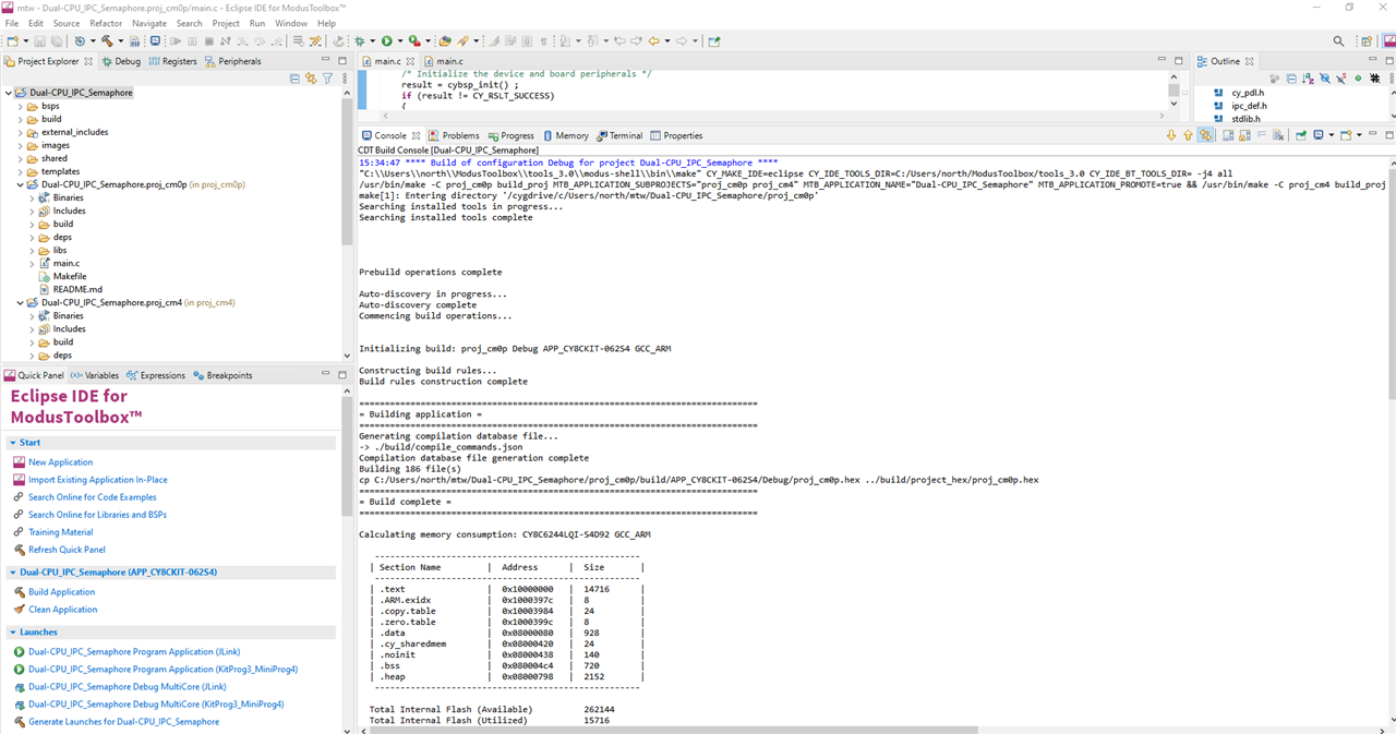
Stage 2 , build for Core M4, and return with no errors.
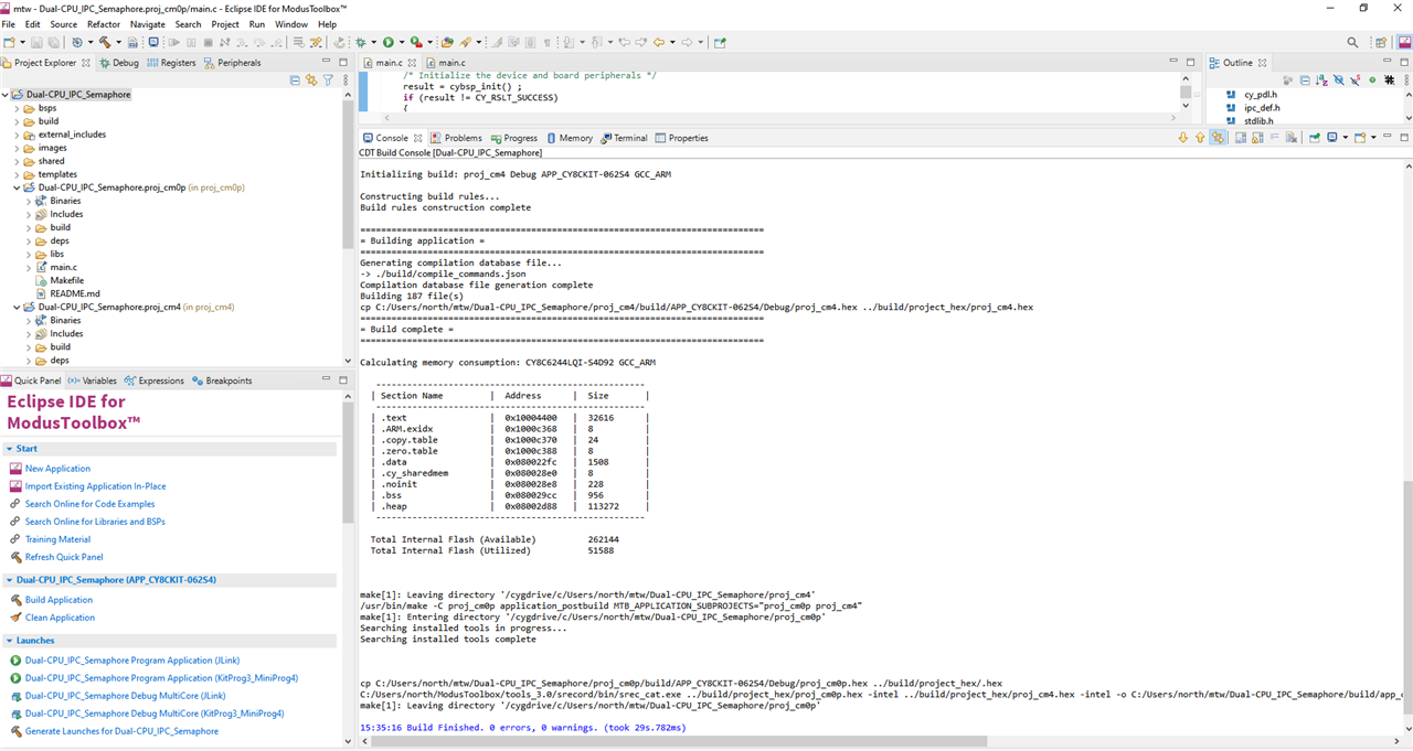
Program the code
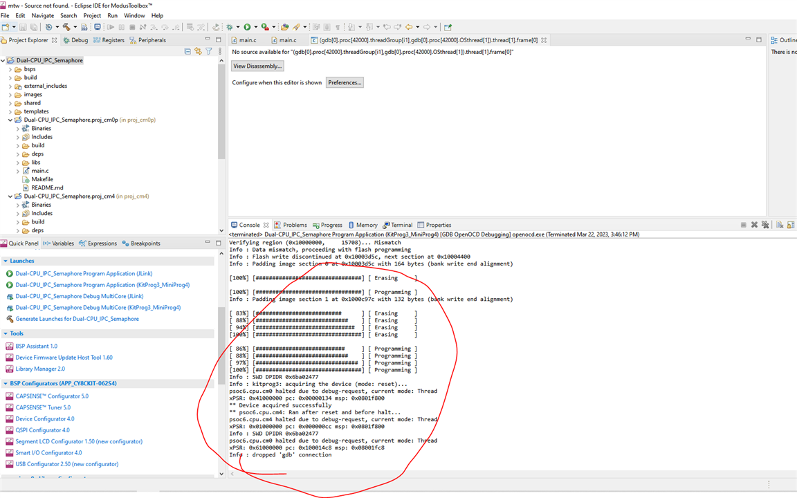
Run with information exchange , toggling interlock status of semaphore channel M0+ core and M4 core
6 Summary
This blog gives general work flow for Dual-CPU project, as start point for construting Tennis Picker Project.
Reference
1) Infineon-PSoC_6_MCU_CY8C61x4_CY8C62x4_Architecture_Technical_Reference_Manual_PSoC_61_PSoC_62_MCU-AdditionalTechnicalInformation-v04_00-EN.pdf
2) Infineon-AN215656_PSoC_6_MCU_Dual-CPU_System_Design-ApplicationNotes-v10_00-EN.pdf
3) https://infineon.github.io/mtb-pdl-cat1/pdl_api_reference_manual/html/group__group__ipc.html
| #3 Rover Platform |
Top Comments