


For all the parts to this project, click here! Smart Doorbell System
Introduction
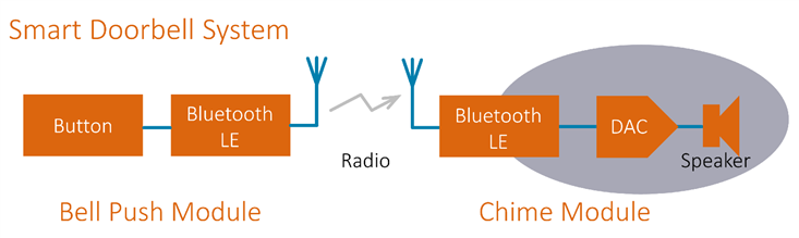
The Smart Doorbell System is an idea for a home bell-push/chime system with better range and features than expected from existing systems!
The project will use a Texas Instruments integrated circuit (IC) called the CC2640R2F which internally contains Bluetooth Low Energy (LE) functionality (this will be a wireless doorbell system!) and built-in microcontroller too.
Naturally a key part of the doorbell system is the chime or tone announcement feature! This blog post discusses the audio (chime) related functionality circled in the diagram below.
If you’re interested to know more about the doorbell project then click the link above to all the earlier parts of the project, otherwise read on here, to see how to incorporate digital audio into a project. The information here is relevant to any project that requires sound, and sound effects. Examples could include Bluetooth musical instruments and toys, and sound or speech alerts for virtually any product.
Why Digital Audio and Sound Synthesis
Traditionally doorbells and alerts used a mechanical chime or buzzer, and in modern times sometimes it is done electronically with a chime generator circuit. Some sound fine but others sound awful with a poorly-replicated chime sound. Some of these electronic circuits use analog sound generators, and some use a digital to analog converter (DAC). It can be a simple DAC; if hi-fi is not required then fairly low-resolution digital to analog converters are perfectly good for intelligible alerts and speech. The landline phone systems throughout the world rely on 8000 samples per second of 8-bit digital audio, although manipulations (A-law and u-law) are done to provide the equivalent of a 13-bit converter.
A few years ago I remember speaking to someone working for the toy company Leapfrog at a trade show, and they mentioned that their toys used higher quality sound chips in their toys compared to the competition (at the time), and this was one of the subtle ways people could tell they were high quality toys compared to the competition. It wasn’t all about looks; parents and children wanted electronic toys to sound good too.
I wanted the ability to have high quality programmable chimes and alerts, so digital audio is ideal. The samples can be stored in memory, or could be generated on the fly using algorithms. Although I didn’t necessarily want CD quality, I figured 16-bit audio was a nice target.
I was keen to explore digital audio with the CC2640R2 Bluetooth LE chip, because it internally has a digital audio interface. I was also keen to perform sound synthesis using algorithms, rather than just store audio files (e.g. WAV files) of sampled chime effects. The CC2640R2 has a high performance ARM Cortex-M3 that runs at a speedy 48MHz, so it would be a shame not to use some of that capability for sound effects algorithms.
High quality sounds and other alerts are really great for Bluetooth projects. Small wearable devices and the higher-end Bluetooth headphones out there already have audio alerts for indicating status and battery level for example. So, the procedure and code described in this blog post should be relevant to non-doorbell projects too.
Digital Audio Interface: I2S
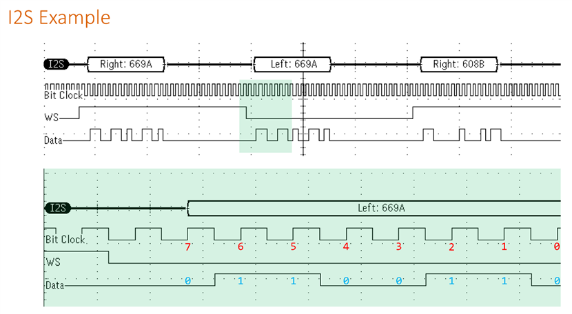
One standard method of transferring digital audio across a circuit board is known as I2S. It is quite flexible and allows for various sample rates and DAC resolution (bits). It is a serial interface and has three main signals; the names vary but often they are known as the bit clock, the word clock (or left/right clock or LR clock), and the data signal. For certain scenarios a high frequency signal called MCLK is also needed (especially for audiophile use-cases) but it isn’t needed for a chime. Bidirectional audio can be achieved by having a second data signal wire. For a chime, bidirectionality is not needed of course.
The diagram below shows the signals. The top half is the zoomed-out view, and the lower half in green is zoomed in to a little area. Data is clocked on the rising edges of the bit clock, and the most significant bit is transferred first. The word or LR clock has a 50% duty cycle, and left and right audio sample data is transferred alternately.
The zoomed-in area shows the byte value 0x66 (the most significant byte from the 0x669A value that is being shown in the zoomed-out view).
I2S Digital to Analog Converter (DAC)
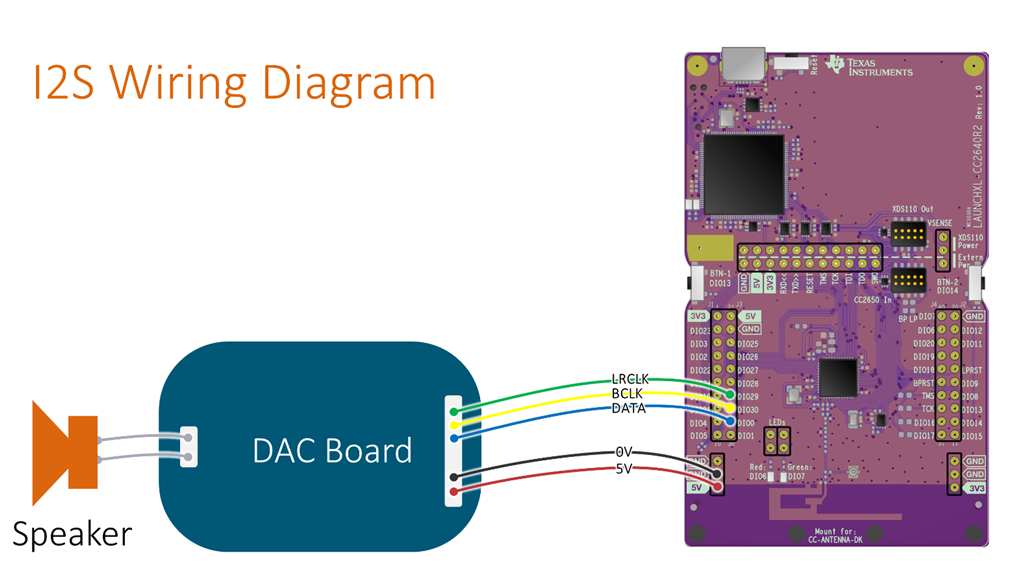
To convert to analog, an external DAC is required. As mentioned in the previous blog post, I decided to test with a DAC board intended for a BeagleBone Black for now (see here: BBB - Building a DAC - part 2 ), until the circuit board is created for this project. The DAC board uses a Texas Instruments PCM5101 chip which requires very little additional circuitry, is of hi-fi quality (it is found in $300 commercial headphone DACs for PCs) and is quite low cost (around $1.20 in quantities of 1000).
The diagram here shows how to wire up the DAC board (any I2S DAC board can be used) to the CC2640R2 board, if you want to try out digital audio and coding sound effects!
I2S Software
Although the CC2640R2 comes with a lot of software, the audio stack is currently in a state of development, with recent commits just a few weeks ago. As a result, it took longer than expected to get the audio functionality working. Anyway, after studying the datasheets and the latest code, I was able to get reasonable results. I may revisit and upgrade to the latest audio stack code at a later date. The information in this section is relevant if you wish to use the code, for example to perhaps build on it and create new projects. Otherwise, you may wish to ignore this section and move on to the next one, which covers sound generation/effects!
The code is attached to the blog post (this code is interim code, and won't be placed on github; it is just attached for anyone who wishes to experiment while I'm still working on this project).
In part 3 I briefly examined the software stack and there was a diagram that showed the key components. As part of DriverLib, Texas Instruments supplies I2S code (in files i2s.c and i2s.h). There is a software stack called I2SCC26XX.c which provides a higher-level interface to audio. The key functions are I2SCC26XX_init, I2SCC26XX_open, and I2SCC26XX_startStream. I wrote a file called audio_handler.c which communicates to that higher-level audio interface.
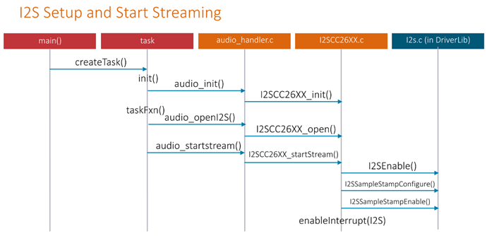
My code registers an interrupt handler and then calls I2SCC26XX_init and I2SCC26XX_open with the desired configuration structures passed as parameters. These configuration structures define the sample rate and bits, and how frequently I want interrupts to occur. When the chime module needs to generate audio, the I2SCC26XX_startStream function is called. As soon as this function is called, the I2SCC26XX software stack will call the interrupt handler every 5 milliseconds.
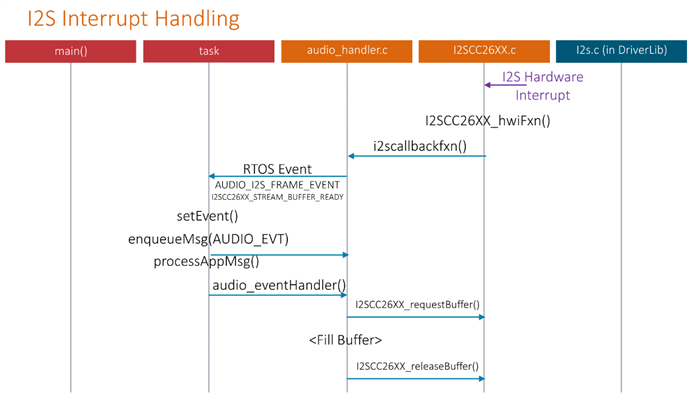
It is the job of my code to use that interrupt to generate a message for the operating system (OS) that the running thread can read; it will fill a buffer every 5 milliseconds with the next chunk of audio that needs to be played. I chose a value of 5 milliseconds to reduce the amount of RAM usage; the more frequent the interrupts, the smaller the buffer needs to be. That’s it! In principle it is easy, but it did take me a few days of effort to figure it out. The development environment is great; it is easy to set up breakpoints but I reduced reliance on that, and used print statements over the serial UART console.
For now, I have hard-coded the bitstream configuration to be 16-bit digital audio at 16k samples per second. This is a fairly good capability for a chime I think; it is sufficient for up to 8kHz sounds. I have chosen a mono output (both the left and the right channels will play the same sound, I don’t need stereo. The relevant files of code are attached to this blog post for anyone who wants to experiment now, rather than waiting for the end result. When it is run on the CC2640R2 board, press the button labelled BTN2 on the board and the I2SCC26XX_startStream function will execute and the audio will be generated.
Sound Synthesis
For a more detailed look at sound synthesis, check out this blog post: Sound Synthesis and the Billion Dollar Paper
Also, there is a nice practical series using the Arduino here: Simple Arduino Music Box: Envelopes
In order to incorporate sound effects into the CC2640R2, techniques from computer music can be used. Nowadays sophisticated music effects are possible with very complex algorithms, but virtually all 1980’s electronic pop music used simpler systems that should be more than adequate for a doorbell chime.
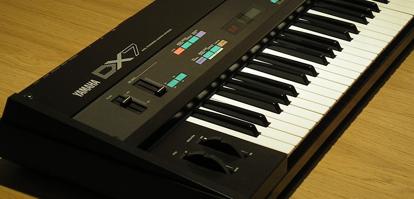
There are basic functions that are needed, such as the ability to create oscillators in software, for any note or to form musical chords for instance. For more realistic sounds, combining oscillators with amplitude adjustment and summation of the outputs, allows for most of the capabilities from the 1980’s : ) These building blocks can be combined for FM synthesis, much like Yamaha music keyboards from that era. Having multiple oscillators provides more ‘voices’ for the effects. Certain combinations can reasonably replicate music instruments like the piano, clarinet and so on. The blog post mentioned earlier describes how this is possible.
The oscillator function was created by storing an array of values that would generate a single cycle of a sinewave. For now, I’ve used 1000 samples of the sine wave. The CC2640R2 has 128 kbytes of Flash memory, so an array of 1000 samples takes negligible storage space. To generate the table, MATLAB code was used (it is further below; see the section titled Sine Arrays in C). The idea is that sounds can be created or synthesized by manipulating the data from this array.
In C++ an oscillator could be formed as an object; I decided to use C code for a bit more portability, and define all oscillator information in a C structure. Each oscillator is set up at any desired frequency (up to 8kHz), phase and amplitude. Then, every 5 milliseconds, the oscillators are ‘played’ for 80 samples (since 80 samples represents 5 milliseconds at 16,000 samples per second) into a buffer. The buffer is streamed out to the DAC of course. For now I have just three oscillators but this can be increased. I still need to implement the rest of the capabilities and for now the code just enables a single oscillator at the desired frequency.
Sine Arrays in C
A simple piece of code was created called csinearray (written in MATLAB) that is useful for creating a C array. It is useful for any project that needs a sine table pre-calculated.
To run it, type something like:
y = csinearray(100, 16, 10, 1);
This will create an array of 100 16-bit signed values and print them to the screen with 10 values per row. Then it can be copy-pasted into your C code!
function [ y ] = csinearray( granularity, bits, perline, signed )
%Generate a C array that constructs a complete (2pi) sine wave
%   Example: y=csinearray(64, 8, 10, 0);
%   where the first parameter is the number of samples of the sinewave
%   the second parameter is the number of bits (for example 8 or 16)
%   and the third parameter is how many values to put on one line of
%   the output of the printed C array and the fourth parameter is
%   set to 1 if a signed output is wanted, or set to 0 for unsigned.
m=2^bits;
m=m/2;
t=0:(2*pi)/granularity:2*pi;
y=sin(t);
if (signed==0)
  y=y+1;
end
y=y*m;
fprintf('const <type> sinearr[');
fprintf('%d', granularity);
fprintf('] = {\n');
fprintf('    ');
cc=1;
lc=0;
fin=0;
while fin==0
    if (signed==0)
      fprintf('0x%04x', round(y(cc)));
    else
      fprintf('0x%04x', typecast(int16(round(y(cc))),'uint16'))
    end
    lc=lc+1;
    cc=cc+1;
    if (cc>granularity)
      fprintf('};\n');
      fin=1;
    elseif (lc>=perline)
      lc=0;
      fprintf(',\n');
      fprintf('    ');
    else
      fprintf(', ');
    end
end % end while

end
As an example, if I run the code as follows:
y = csinearray(24, 8, 5, 1);
The output is:
const <type> sinearr[24] = {
0x0000, 0x0021, 0x0040, 0x005b, 0x006f,
0x007c, 0x0080, 0x007c, 0x006f, 0x005b,
0x0040, 0x0021, 0x0000, 0xffdf, 0xffc0,
0xffa5, 0xff91, 0xff84, 0xff80, 0xff84,
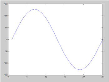
0xff91, 0xffa5, 0xffc0, 0xffdf};
Plotting it reveals this sine wave:
Putting It All Together
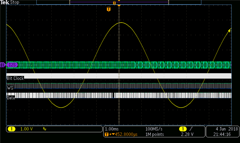
The work in this blog post was tested out, and the oscilloscope screenshot shows the result; a 200Hz good quality output.
Summary
This blog post focussed on the audio output capabilities, and successfully generated a good quality tone. The structure is in place for more advanced sounds.
A full sound synthesiser isn’t perhaps in the scope of this design challenge, but I intend to generate interesting sounds, including hopefully using FM synthesis. I believe this will be useful for many projects that require audio alerts. Some Bluetooth wearables and other devices may not always have space for a display, but tones, chimes and speech are another option for them. I think it’s nice to have good differentiators like high quality effects, compared to competitor products. This is fairly straightforward to do since the CC2640R2 supports digital audio and has the performance for implementing a synthesizer.
Next Steps
The next blog post will post a bit of a challenge, work trip coming up! Anyway, hopefully I can now proceed with the printed circuit board design, since the work in this blog post has confirmed for me that a key part of the functionality, the chime audio output, can function using digital audio. I needed this, to feel more confident laying out the circuit.
Top Comments