


BLOG# 2 - Beats Per Minute Nano
A Heart Rate Monitor using the Arduino Nano 33 IoT Board
Research & Experimentation
This is my 2nd blog post in a series of blog post for the Design Challenge: Design for A Cause 2021
Updated
version 1.2
| <<< PREVIOUS BLOG | NEXT BLOG >>> |
|---|---|
| Blog# 3 Beats Per Minute Nano - System Design |
INTRODUCTION
Since I have not used Arduino before I will need to research and experiment with the IDE and Connecting sensors and other components to it.
This blog will document my attempts to learn more about the Arduino Nano 33 IoT.
The Challenge Kit Arduino Nano 33 IoT
Connecting the Nano to the IDE.
If your already familiar with the Nano IDE, you can skip this section
-
-
Development environment
- My development environment consist of 2 pc's. One running Windows 10 and the other running Linux Ubuntu (My OLD/NEW Linux Developer workstation.).
-
- I am using VSCode with the PlatformIO extension, which is claimed to function like the Arduino IDE. I will also be using the Arduino IDE. I use VS Code and I'm interested in using it to develop for the Nano.
-
- There is plenty of instructions on using PlatformIO on YouTube and the Internet. I have included my links in the references.
-
- I will be presenting my notes on getting it up and running on my Windows10 and Ubuntu system.
-
- Using the video on YouTube VS CODE With PlatformIO follow the following steps:
-
-
-
-
- Install the Arduino IDE, if you do not have it already installed on your Workstation...
- Follow the instructions on Getting started with the Arduino NANO 33 IoT to experiment with the IDE and run the blink
- Install VS Code
- Add the PlatformIO extensions
- Attach the Nano to the workstation and review this section of the video at: 13:56 - PlatformIO Basics with Arduino Uno
- Try the demo sketch from the video
-
-
-
-
COMMENTS
- I installed the Arduino IDE as suggested in the PlatformIO video. But I jumped right into VS Code and ran into problems finding the Nano 33 IoT and the code did not run.
- Then I went back to step2 and ran thru the instruction there. I was able to find the Nano 33 IoT device and the blink sketch worked fine.
- Then I went back into VS Code and created a new project and the Nono 33 IoT worked fine?
- I then followed the same steps on my Linux Workstation
- I installed the Arduino IDE as suggested in the PlatformIO video. But I jumped right into VS Code and ran into problems finding the Nano 33 IoT and the code did not run.
-
-
-
Experiments
- I will be experimenting with a few example sketches. Here are my Notes
- I Tried the following experiments on the PlatformIO Documentation site:
- Unit Testing of a Blink Project
- NOTES
- I watched and used the following YouTube Videos to Experiment with the Development environment.
- I will be experimenting with a few example sketches. Here are my Notes
-
-
-
-
-
- Another YouTube Video
-
-
-
-
-
-
-
- NOTES:
-
-
-
Connecting the Heart Sensor to the Nano
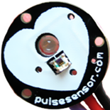
- I tested the Heart rate sensor by following the videos on the PulseSensor website
- And using some of the examples in the PuleSensor Playground Library
-
-
A Library of Examples
-
This video shows you the best way to install the PulseSensor.com code examples.
-
Pro Tip: You don't need GitHub.com to download our code anymore. Use the Arduino IDE for stable and tested code.
- The Video details how to install the "PulseSensor Playground" on the Arduino IDE. The following steps are sumerized here:
- go to Sketch > Include Library > Manage Library...
- In the search box place "PluseSensor"
- Install or update to the latest version.
- Once this library is installed you will see the PulseSensor examples in IDE dropdown!
- To select an example project, go to: `File > Examples > PulseSensor Playground > GettingStartedProject`.
- To install the PlusSensor Playground in the VSCode PlatformIO IDE. Following the following steps.
- If you do not have a project open yet start a new project.
- In VSCode go to the PlatformIO the "Libraries" TAB.
- In the search box place "PluseSensor"
- Press the Add to Project button.
-
-
The "GettingStartedProject"
- This project uses the Arduino UNO. But here are the pins you can connect to the Nano 33 IoT.
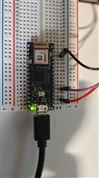
- You will be connecting the following wires from the PulseSensor to the Nano 33 IoT
- I Have the 3 pins configured as the last project
- RED to Pin 2 - +3V3
- Black to Pin 14 - GND
- Purple to Pin 4- A0 Analog ADC
- I Have the 3 pins configured as the last project
-
-
- Photo of the Nano 33 IoT on a breadboard the Pulse sensor wires connected.

-
-
- Using the Arduino IDE
-
-
-
-
- Once you've installed the Playground, go to: File > Examples > PulseSensor Playground > Getting Started
- Upload to your Arduino Nano, and place the PulseSensor on your fingertip. You should see Arduino's built-in LED (near Pin 13) blink with you heartbeat.
- This basic sketch is designed to work with the Arduino Serial Plotter, a tool for visualizing the kind of analog signals that Pulse Sensor puts out.
- While the sketch is running and your Arduino board is connected to your computer USB, click on: Tools > Serial Plotter
-
-
-
-
-
- My video of the program running with the serial plotter running.
-
-
-
-
- Using VSCode PlatformIO IDE
- If you have installed the PulseSensor Librar y follow the steps above.
- Then cut and past the code from the Arduino IDE in the main.c program.
- Attach the USB cable to the Nano.
- press the -> at the bottom of the IDE to compile and run the code
- press the icon that looks like a electrical plug on the bottom toolbar to open the Serial monitor.
- Using VSCode PlatformIO IDE
-
-
- Getting (Calculating) BPM:
-
This page describes 3 examples in the PluseSensor Playhouse library.
- Getting_BPM_to_Monitor
- PulseSensor_BPM
- PulseSensor_BPM_Alternative
-
-
- There are 3 different ways to get BPM from the PulseSensor.
- As in the last example it uses the Arduino Nano.
- I Have the 3 pins configured as the last project
- RED to Pin 2 - +3V3
- Black to Pin 14 - GND
- Purple to Pin 4- A0 Analog ADC
- The first Example "Getting_BPM_to_Monitor"
- I was unable to get it to run? Why?
-
-
- It would not give any error, just not display the blinking LED and the Terminal output did not display as described
- Seems that this example does not work on the Nano 33 IoT
- The second Example PulseSensor_BPM
- Does not work either.
- Just blinked the Nano orange LED rapidly.
- The third Example PulseSensor_BPM_Alternative
- Worked great !!
- This is the only example out of the three that works on the NANO 33 IoT
-
- PulseSensor Processing Visualizer Sketch
- This uses the Tool "Processing ", that can be downloaded from https://processing.org/download/
- Install this sketch from the Git repository and run it to display data from the Example PulseSensor_BPM_Alternative
- Getting (Calculating) BPM:
-
-
-
- You will need to change the variable called outputType, and by default it is set to SERIAL_PLOTTER. You need to change it to PROCESSING_VISUALIZER
- Here it is running on my Windows Workstation
-
-
-
-
Notes and Comments
- I was successful in experimenting with both the Ardunio IDE and VScode with PlatfomIO extensions.
- Both of the two project mentioned above were completed with the Pin assignment described.
- Both very helpful
- On the "Getting (Calculating) BPM"
- Example 1
-
- I was unable to get it running.
- It would not give any error, just not display the blinking LED and the Terminal out did not run?
- Not sure why
- I was unable to get it running.
- Example 2
-
- I Was Unable to get working correctly
- HOWEVER The code stipulates that Interrupts are used and it appears that Nano 33 IoT does not support interrupts.
- The Orange LED will blink rapidly if it fails in the setup method.
- Example 3
- Worked great
- It does not include interrupts
- The BPM and IBI values get sent over Serial and can be visualized by the Arduino Serial Plotter,
- OR with our Processing Visualizer, or Pulse Sensor Mac App.
-
-
- I was unable to get the debugger working in PlatformIO and did not see the existence of on in the Arduino IDE?
- It WOULD BE Nice if there was one.
- If anyone knows what I'm missing Please let me know
- It WOULD BE Nice if there was one.
- I was unable to get the debugger working in PlatformIO and did not see the existence of on in the Arduino IDE?
Connecting the OLED to the Nano
-
An OLED Example Project
- II was able to connect the OLED display to my Arduino by following the following project on instructables.com/
-
My Notes and Comments
- The example is using a different Nano model, I was able to get it working on my Nano 33 IoT just fine
-
The example wired an external 5v supply, but I found that a connection to my Nano +3v3 pin worked fine.
- I placed the OLED on the same breadboard as the PulseRate sensor described above .
- The 4 pins of the OLED, are inserted to the breadboard female pins 24, 25 ,26 and 27, and jumper wires are connected to the Nano breadboard pins 8,9,2 and 14 respectively.
- GND pin (27) - Nano GND (14)
- VCC pin (26) - Nano +3v3 pin (2)
- SCL pin (25) - Nano A5 pin (9)
- SDA pin (24) - Nano A4 pin (8)
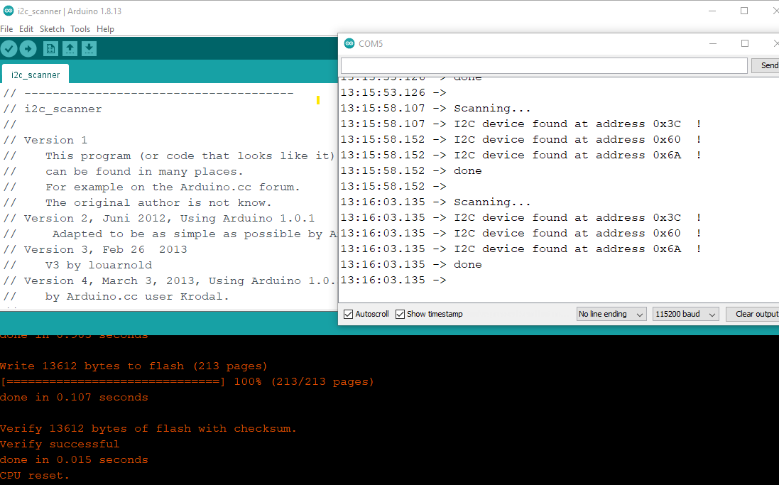
- It was suggested to run the sketch I2C_Scanner, to find out the I2c address of the OLED board, which I did and it return 3 addresses. I assumed 2 were for the Nano 33 IoT. So I unplugged the OLED and ran the Sketch. Sure enough, by process of elimination, I was able to rule those 2 out of the possible addresses.
- The 4 pins of the OLED, are inserted to the breadboard female pins 24, 25 ,26 and 27, and jumper wires are connected to the Nano breadboard pins 8,9,2 and 14 respectively.
-
-
-
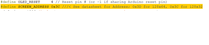
I found that the address of the OLED was the same as the one defined in the code described later in another Step. 
-
-
-
-
-
I2C_Scanner run 
-
-
-
-
- Now you are instructed to Install the OLED Libraries from the IDE.
- I found that installing them with the Arduino IDE library manager worked out great. The Example Project gives the links to the 2 GitHub repos if your interested.
- I also found it easy to search for "Adafruit_SSD1306" and installing it while clicking on the option to include dependence's, installed the "Adafruit_GFX_Library" as well. Nice!!
- Finally I ran the OLED test sketch described in the Example Project
- I opened the example in
- "Examples/AdaFruitSSD13061/ssd1306_128x64_i2c"
- I did not have to change the I2C Address as described in the example project., because it was already set to the value of 0x3c,
- Built it and ran it (Refer to video below)
- I ran it for about 15 minutes on the +3v3 of the Nano 33 IoT and it ran the dropping stars until I unplugged it.
- I opened the example in
- Now you are instructed to Install the OLED Libraries from the IDE.
-
-
Results Videos
| Breadboard Front View | Breadboard Pin view |
|---|---|
Conclusions and Summary
Summary
I conducted experiments on the following
-
The Arduino IDE to connect to the Nano 33 IoT.
- The Arduino IDE and the VSCode extension PlatformIO
- Used both Windows 10 and Linux workstation to perform my experiments.
- Connected the PulseSensor to the Nano 33 IoT and conducted some experiments.
- Connected the OLED to the Nano 33 IoT
Conclusions
- This was a very long blog, but I found it necessary to understand the Arduino IDE, the Nano 33 IoT and the connections of PulseSensor and the OLED.
- This will give me the understanding of the Tech, so I can design ,implement and test my project.
- I have only scratched the surface of the capabilities of the Nano 33 IoT. I have listed some other experiments to conduct in Appendix B. I'd like to circle back on these after I finish the design challenge. But for now onto the next Blog.
Appendices
Appendix A - PIN Descriptions
|
||||||||||||||||||||||||||||||||||||||||||||||||||||||||||||||||||||||||||||||||||||||||||||||||||||||||||||||||||||||||||||||||||||||||||||||||||||||||||||||||
|---|---|---|---|---|---|---|---|---|---|---|---|---|---|---|---|---|---|---|---|---|---|---|---|---|---|---|---|---|---|---|---|---|---|---|---|---|---|---|---|---|---|---|---|---|---|---|---|---|---|---|---|---|---|---|---|---|---|---|---|---|---|---|---|---|---|---|---|---|---|---|---|---|---|---|---|---|---|---|---|---|---|---|---|---|---|---|---|---|---|---|---|---|---|---|---|---|---|---|---|---|---|---|---|---|---|---|---|---|---|---|---|---|---|---|---|---|---|---|---|---|---|---|---|---|---|---|---|---|---|---|---|---|---|---|---|---|---|---|---|---|---|---|---|---|---|---|---|---|---|---|---|---|---|---|---|---|---|---|---|---|
(*) As opposed to other Arduino Nano boards, pins A4 and A5 have an internal pull up and default to be used as an I 2C Bus so usage as analog inputs is not recommended. Opposed to Arduino Nano boards that support 5V operation, the 5V pin does NOT supply voltage but is rather connected, through a jumper, to the USB power input. |
Appendix - B Future Enhancements of interest
I am also interested in these topics and will experiment with them after I get the Heart rate sensor design running for the Challenge.
Using the Arduino IoT Cloud
LINK to Project page
Complete the Project on the Nano 33 IoT
Notes and Comments
Experimenting with selected projects from the Element14 community: Blynk, IFTTT, Azure
LINK to Project page
Complete the Project on the Nano 33 IoT
Notes and Comments
Using MongoDB Atlas if Possible?
Connect to MongoDB Atlas with C
Write the data from the Heart Sensor Project to the Database.
REFERENCES
|
|
|---|---|
Installing VS code and the PlatformIO extensionsto your Workstation that the Nano will be plugged into. |
VS CODE With PlatformIO |
PlatformIO Official Site |
Official Site |
PlatformIO Tutorials and Examples |
PlatformIO Tutorials and Examples |
Unit Testing of a Blink ProjectUsing VS Code and PlatformIO The goal of this tutorial is to demonstrate how simple it is to use Unit Testing. |
Unit Testing of a Blink Project |
PlatformIO YouTube Video TutorialWould you like to have a better tool to program your Arduino or ESP boards? More productive, more flexible, but still compatible with all our Arduino sketches and libraries. Also easy to use? |
|
How to Program Arduino in VSCode (Using Platform.io) |
How to Program Arduino in VSCode (Using Platform.io) |
|
Arduino Nano 33 IoT Spec sheet Describes the 30 pin connectors. |
Speci sheet |
| <<< PREVIOUS BLOG | NEXT BLOG >>> |
|---|---|
| Blog# 3 Beats Per Minute Nano - System Design |