element14 Community
element14 Community
    Register Log In
  • Site
  • Search
  • Log In Register
  • About Us
  • Community Hub
    Community Hub
    • What's New on element14
    • Feedback and Support
    • Benefits of Membership
    • Personal Blogs
    • Members Area
    • Achievement Levels
  • Learn
    Learn
    • Ask an Expert
    • eBooks
    • element14 presents
    • Learning Center
    • Tech Spotlight
    • STEM Academy
    • Webinars, Training and Events
    • Learning Groups
  • Technologies
    Technologies
    • 3D Printing
    • FPGA
    • Industrial Automation
    • Internet of Things
    • Power & Energy
    • Sensors
    • Technology Groups
  • Challenges & Projects
    Challenges & Projects
    • Design Challenges
    • element14 presents Projects
    • Project14
    • Arduino Projects
    • Raspberry Pi Projects
    • Project Groups
  • Products
    Products
    • Arduino
    • Avnet Boards Community
    • Dev Tools
    • Manufacturers
    • Multicomp Pro
    • Product Groups
    • Raspberry Pi
    • RoadTests & Reviews
  • Store
    Store
    • Visit Your Store
    • Choose another store...
      • Europe
      •  Austria (German)
      •  Belgium (Dutch, French)
      •  Bulgaria (Bulgarian)
      •  Czech Republic (Czech)
      •  Denmark (Danish)
      •  Estonia (Estonian)
      •  Finland (Finnish)
      •  France (French)
      •  Germany (German)
      •  Hungary (Hungarian)
      •  Ireland
      •  Israel
      •  Italy (Italian)
      •  Latvia (Latvian)
      •  
      •  Lithuania (Lithuanian)
      •  Netherlands (Dutch)
      •  Norway (Norwegian)
      •  Poland (Polish)
      •  Portugal (Portuguese)
      •  Romania (Romanian)
      •  Russia (Russian)
      •  Slovakia (Slovak)
      •  Slovenia (Slovenian)
      •  Spain (Spanish)
      •  Sweden (Swedish)
      •  Switzerland(German, French)
      •  Turkey (Turkish)
      •  United Kingdom
      • Asia Pacific
      •  Australia
      •  China
      •  Hong Kong
      •  India
      •  Korea (Korean)
      •  Malaysia
      •  New Zealand
      •  Philippines
      •  Singapore
      •  Taiwan
      •  Thailand (Thai)
      • Americas
      •  Brazil (Portuguese)
      •  Canada
      •  Mexico (Spanish)
      •  United States
      Can't find the country/region you're looking for? Visit our export site or find a local distributor.
  • Translate
  • Profile
  • Settings
Enchanted Objects
  • Challenges & Projects
  • Design Challenges
  • Enchanted Objects
  • More
  • Cancel
Enchanted Objects
Blog More Datasheet Studying
  • Blog
  • Forum
  • Documents
  • Polls
  • Files
  • Events
  • Mentions
  • Sub-Groups
  • Tags
  • More
  • Cancel
  • New
  • Share
  • More
  • Cancel
Group Actions
  • Group RSS
  • More
  • Cancel
Engagement
  • Author Author: crjeder
  • Date Created: 11 Jun 2015 8:06 PM Date Created
  • Views 1351 views
  • Likes 3 likes
  • Comments 6 comments
  • sama5d4
  • smart_key_hooks
  • atmel_sama5d4
  • enchanted_objects
  • pwm
  • arm
Related
Recommended

More Datasheet Studying

crjeder
crjeder
11 Jun 2015

Some of you might have recognized that I omitted one significant detail in the C code in my last post "Use WS2812B on the SAMA5D4 Xplained":

How is the correct PWM clock frequency of 2.4 MHz configured?


Clocks, Clocks and more Clocks

The peripherals of the SAMA5D44 (no, this is not a typo, that's the name of the SOC on the SAMA5D4 Xplainded board) all receive their own clock signal. Relevant for PWM is the peripheral clock as shown in the diagram from the datasheet (page 1448):

image

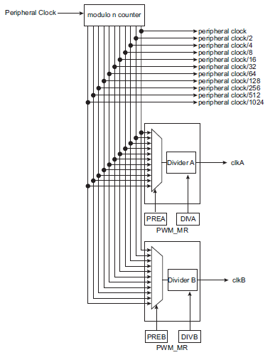
Most clocks in the SOC are controlled by the Power Management Controller. Contrary to the name this component does not (only) turn the power of integrated devices on and off, it mainly controls the distribution of clock signals. (By not providing a clock signal to a specific component it is turned off.) The programmer can individually request those peripheral clocks to be turned on or off and can select a division factor to be applied to the boards master clock MCK. The factor can be 1, 2, 4 or 8 and is applied to the master clock.

The frequency of the peripheral clock can be calculated by BOARD_MCK / divider. The divider can be read / set through the PMC_PCR register and BOARD_MCK is defined in board.h. This would be nice and easy to use but would work only in a bare metal environment where the clock can not be influenced by other processes. But since I do not intend to dump the Linux running on the board I have to consider these values as variables. Back to the datasheet. It turns out that the relevant values for master clock are the PMC Master Clock Register:

  • CSS: Master/Processor Clock Source Selection
  • PRES: Master/Processor Clock Prescaler
  • MDIV: Master Clock Division

Those values determine the true value of MCK (master clock).

MDIV is an other divisor for the master clock. It can be 1, 2, 3 or 4

The prescaler supports the division by a power of 2 of the selected clock between 1 and 64. The PRES and MDIV fields in PMC_MCKR programm the prescaler.

CSS can have several values to select one of the following clock sources:

  • Slow Clock
  • Main Clock
  • PLLACK
  • UPLL Clock

Now we know which clock source is selected an how it's frequency is divided to yield the peripheral clock. Next step is to find the frequency of the source. All source clocks are provided by the Clock Generator.

Slow clock can be selected to be either the 32 kHz on chip RC oscillator or the external 32768 Hz quartz. Selection is made by the OSCSEL bit in the Slow Clock Controller Configuration Register.

Main clock similarly can be configured to use internal or external 12 MHz sources, therefore is always 12 MHz.

UPLL generates frequencies which are higher than the base frequency (main ***) with a PLL. It is programmed through MULA field of the PMC Clock Generator PLLA Register. The MULA field is the PLLA multiplier factor. This parameter can be programmed between 0 and 127. If MULA is set to 0, PLLA is turned off, otherwise the PLLA output frequency is PLLA input frequency multiplied by (MULA + 1). The output is optionally dived by 2 (selected by PLLADIV2) the to generate PLLACK output.

UPLL Clock is fixed to 480 (40 x 12) MHz for USB High Speed.

The result is divided by the MCK_DIV to yield the frequency of the periphal clock wihch is the input into the PWM clock generation.

In C the above looks like that:

int get_periphal_clock_frequency(uint32_t ID)
 {
    int frequency, mck_div, mula;

    switch(PMC->PMC_MCKR & PMC_MCKR_CSS_Msk)
    {
        case 0:                                 // Slow Clock is selected
            if(SCKC->SCKC_CR & SCKC_CR_OSCSEL)  // XTAL selected
                frequency = 32768;
            else                                // internal RC selected
                frequency = 32000;
            break;
        case 1:                                 // Main Clock is selected
            frequency = 12000000;
            break;
        case 2:                                 // PLLACK is selected
            mula = (PMC->CKGR_PLLAR & CKGR_PLLAR_MULA_Msk) >> CKGR_PLLAR_MULA_Pos;
            frequency = 12000000 * (mula +1);
            break;
        case 3:
            frequency = 480000000;
            break;
    }

    PMC->PMC_PCR = PMC_PCR_PID(ID);     // config PMC register read mode for PWM clock
    mck_div = (PMC->PMC_PCR & 0x00ff00u) >> 8;  // read MCK divider -> PWM clock
    frequency = frequency / mck_div;
    return(frequency);
}
 }


Generating the desired frequencies


Back to the original problem, calculate the divisors for the PWM clock:

Now that we know the input to the above diagram we can go ahead and do some basic math. To calculate the parameters PREA and DIVA in order to get the desired frequency we have to calculate and factorize the required divider.

divider = peripheral_clock / desired_frequency

split divider in the form  2^prea×diva

Example:

divider = 260

factors of 260: 2^2×5×13

=> prea = 2 and  diva = 5×13 = 65

How is factorization done? The answer is astonishingly simple: do a trial division! Since we only need to know the factor which is a power of two this is further simplified to this:

int calculate_PWM_dividers(int frequency, int *div, int *pre)
 {
    uint32_t mck_div, f;
    int n;

    frequency = abs(frequency);             // no negative frequency
    f = get_periphal_clock_frequency(ID_PWM);
    *div = f / frequency;                    // required divisor

    // split div into pre and div
    // facorization of divider
    // pre -> power of 2
    // div = all other facors
    for(n=1; n <= 10; n++)
        if(*div % ((int) pow(2, n)) != 0) // if not a multiple of 2^n
            *pre = n - 1;         // then it was a multiple of 2^n-1
    *div = *div / ((int) pow(2, *pre));     // new divisor is the rest
 }

Wrap this code nicely in some error handling code and that's it.

  • Sign in to reply

Top Comments

  • crjeder
    crjeder over 10 years ago in reply to Workshopshed +1
    Plan double the time you are planning to spend I never thought that it could be that complicated to use such a simple feature like PWM. I guess that's the reason why AVR is still popular.
  • crjeder
    crjeder over 10 years ago in reply to Jan Cumps +1
    Of course you can have the code. I use c9.io as IDE so if you have an account we could try online colaboration, if not I can send it to you. At the moment I have not even compiled the code, maybe I should…
  • crjeder
    crjeder over 10 years ago in reply to Jan Cumps

    I discovered because I own a BeagleBone Black which comes with c9 preinstalled and I love it. Yo can easily develop and test e. g. node.js code. I never tested the collaboration, though. If you send me a PM with your e-mail addres I'll add you to the workspace.

    • Cancel
    • Vote Up 0 Vote Down
    • Sign in to reply
    • More
    • Cancel
  • Jan Cumps
    Jan Cumps over 10 years ago in reply to crjeder

    It's the first time that I see cloud9. I may give this a go (the ubuntu workspace sounds interesting)

    • Cancel
    • Vote Up 0 Vote Down
    • Sign in to reply
    • More
    • Cancel
  • crjeder
    crjeder over 10 years ago in reply to Jan Cumps

    Of course you can have the code. I use c9.io as IDE so if you have an account we could try online colaboration, if not I can send it to you.

    At the moment I have not even compiled the code, maybe I should do that first.

    • Cancel
    • Vote Up +1 Vote Down
    • Sign in to reply
    • More
    • Cancel
  • Jan Cumps
    Jan Cumps over 10 years ago

    crjeder I've been checking the previous post and this one. I got it that you didn't use the Linux driver and ASF solutions. One thing I couldn't understand is: are you running the compiled program on Linux or on bare metal?


    It would also be great if you could upload your program, even if it's in incomplete state. You're doing a few things there that I'd like to replicate.


    Regards, Jan

    • Cancel
    • Vote Up 0 Vote Down
    • Sign in to reply
    • More
    • Cancel
  • crjeder
    crjeder over 10 years ago in reply to Workshopshed

    Plan double the time you are planning to spend image

    I never thought that it could be that complicated to use such a simple feature like PWM. I guess that's the reason why AVR is still popular.

    • Cancel
    • Vote Up +1 Vote Down
    • Sign in to reply
    • More
    • Cancel
>
element14 Community

element14 is the first online community specifically for engineers. Connect with your peers and get expert answers to your questions.

  • Members
  • Learn
  • Technologies
  • Challenges & Projects
  • Products
  • Store
  • About Us
  • Feedback & Support
  • FAQs
  • Terms of Use
  • Privacy Policy
  • Legal and Copyright Notices
  • Sitemap
  • Cookies

An Avnet Company © 2025 Premier Farnell Limited. All Rights Reserved.

Premier Farnell Ltd, registered in England and Wales (no 00876412), registered office: Farnell House, Forge Lane, Leeds LS12 2NE.

ICP 备案号 10220084.

Follow element14

  • X
  • Facebook
  • linkedin
  • YouTube