


More Details on the WS2812B
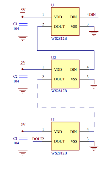
The mysterious signal from my previous post was for a WS2812B LED. It was shown in Fairy Dust has arrived!. It is a RGB LED with integrated controller. The LEDs can be easily chained together:
If you are really crazy you can build something like this with those:

With an estimated power draw of 3 KW  and 10.000 WS2812 LEDs this is really insane.
But back to the lab:
Besides of the power supply the LEDs use only a single pin for data transfer. The data is transmitted bit-wise by the "mysterious signall" with 8 bit per RGB but in GRB order (for whatever reason). After the last LED a reset signal is sent to start all over again. This is shown in the graph from the datasheet:
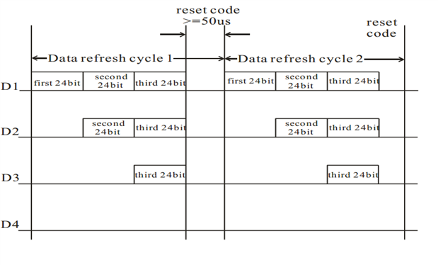
mcb1 pointed me to a link which gives valuable insight into the timing constraints of the protocol. Bottom line: The timing does not matter much as long as you can make sure that around the middle of the period the DIN line has the correct signal applied. No fancy assembly code needed and no high clock frequencies.
PWM Implementation of the WS2812B Protocol
The Basic flow is straight forward:

PWM on the SAMA5D4 Xplained
There are several options to programm the board. Those I evaluated are (form highest abstraction to lowest):
- Linux driver and API
- Atmel Software Framework (ASF)
- Low level GPL API by Atmel
The Linux driver does not support any kind of signaling the end of the period. More capable and less abstract is ASF but AFAIK SAMA5 series is not (yet) supported. So back to the ground level and (allmost) manually programm the registers using the GPL API. The following part of the C-code is heavily commented with information from (mainly) the datasheet. It is not yet ready and definitely not tested. But as it has taken me so long to find all this information it is time to publish it anyway:
/****
* PWM Initialization
* ------------------
*
* Before using the PWM macrocell, the programmer must first enable the
* peripheral clock in the Power Management Controller (PMC).
  ****/
    PMC_EnablePeripheral(ID_PWM);
    /* Disable to configure the first PWM channel */
    PWMC_DisableChannel(PWM, EXAMPLE_PWM_CHANNEL_INDEX0);

/****
* Before enabling the channels, they must be configured by the software
* application as described below: (p 1466)
* - Unlock User Interface by writing the WPCMD field in the PWM_WPCR.
****/
    PWM.PWM_WPCR |= PWM_WPCR_WPCMD;
/****
* - Configuration of the clock generator (DIVA, PREA, DIVB, PREB in the
*   PWM_CLK register if required).
****/
    mode = PWM_CLK_PREA() | (PWM_CLK_DIVA()); // require 2.4 MHz
    PWMC_ConfigureClocks(PWM, mode);
/****
* - Selection of the clock for each channel (CPRE field in PWM_CMRx)
****/
    mode = 0; // Begin configuring the CPRE register
    mode |= PWM_CMR_CPRE(PWM_CMR_CPRE_CLKA);
/****
* - Configuration of the waveform alignment for each channel
*   (CALG field in PWM_CMRx)
****/
    mode |= !PWM_CMR_CALG; // left alligned
/****
* - Selection of the counter event selection (if CALG = 1) for each
*   channel (CES field in PWM_CMRx)
****/
    mode |= !PWM_CMR_CES; // Don't care since CALG = 0
/****
* - Configuration of the output waveform polarity for each channel
*   (CPOL bit in PWM_CMRx)
  ****/
    mode |= PWM_CMR_CPOL;
    PWM.PWM_CH_NUM[0].PWM_CMR = mode; // Write CMR register
/****
* - Configuration of the period for each channel (CPRD in the
*   PWM_CPRDx register). Writing in PWM_CPRDx register is possible
*   while the channel is disabled. After validation of the channel, the
*   user must use PWM_CPRDUPDx register to update PWM_CPRDx as
*   explained below.
*   Source Clock Selection Criteria (p 1467):
* -- The event number written in the Period Register gives the PWM
*    accuracy. The Duty-Cycle quantum cannot be lower than 1/CPRDx
*    value. The higher the value of PWM_CPRDx, the greater the
*    PWM accuracy.
  ****/
    PWM.PWM_CH_NUM[0].PWM_CPRD |= PWM_CPRD_CPRD(3); // Period length
/****
* - Configuration of the duty-cycle for each channel (CDTY in the
*   PWM_CDTYx register). Writing in PWM_CDTYx register is possible
*   while the channel is disabled. After validation of the channel, the
*   user must use PWM_CDTYUPDx register to update PWM_CDTYx as
*   explained below.
  ****/
    PWM.PWM_CH_NUM[0].PWM_CDTY |= PWM_CDTY_CDTY(0);
/****
* - Configuration of the dead-time generator for each channel (DTH and
*   DTL in PWM_DTx) if enabled (DTE bit in the PWM_CMRx). Writing in
*   the PWM_DTx register is possible while the channel is disabled.
*   After validation of the channel, the user must use PWM_DTUPDx
*   register to update PWM_DTx
  ****/
/****
* - Selection of the synchronous channels (SYNCx in the PWM_SCM
*   register)
  ****/
    PWM.PWM_SCM |= PWM_SCM_SYNC0;
/****
* - Selection of the moment when the WRDY flag and the corresponding
*   DMA transfer request are set (PTRM and PTRCS in the PWM_SCM
*   register)
*
*      PTRM = 0 => DMA transfer request and WRDY are set to ‘1’ as soon as
*   the update period is elapsed
  ****/
    PWM.PWM_SCM |= PWM_SCM_PTRM;
/****
* - Configuration of the update mode (UPDM in PWM_SCM register)
  ****/
    PWM.PWM_SCM |= PPWM_SCM_UPDM_MODE1;
/****
* - Configuration of the update period (UPR in PWM_SCUP register)
*   if needed
  ****/
    PWM.PWM_SCUP = PWM_SCUP_UPR(0); // UPR = 0 -> update every period
/****
* - Configuration of the comparisons (PWM_CMPVx and PWM_CMPMx)
  ****/
    //PWM.PWM_CH_NUM[0] =
/****
* - Configuration of the event lines (PWM_ELMRx)
  ****/
    PWM.PWM_ELMR |= PWM.PWM_ELMR_CSEL0;
/****
* - Configuration of the fault inputs polarity (FPOL in PWM_FMR)
  ****/
    // Unused
/****
* - Configuration of the fault protection (FMOD and FFIL in PWM_FMR,
*   PWM_FPV and PWM_FPE1)
  ****/
    // Unused
/****
* - Enable of the Interrupts (writing CHIDx and FCHIDx in PWM_IER1, and
*   writing WRDYE, ENDTXE,TXBUFE, UNRE, CMPMx and CMPUx in PWM_IER2)
  ****/
    PWM.PWM_IER1 |= PWM_IER1_CHID0;
    PWM.PWM_IER2 |= PWM_IER2_WRDY;
    //PWMC_EnableChannelIt(*PWM, 0); //PWM_IER1 (same?)
/****
* - Enable of the PWM channels (writing CHIDx in the PWM_ENA register)
****/
    PWMC_EnableChannel(PWM, EXAMPLE_PWM_CHANNEL_INDEX0);
This is only the setup part, I have still to find out how to calculate the clock frequency / how to programm prescaler and divider to produce a 2.4 MHz PWM signal.
For the beginning I will poll the WRDY signal to find the end of the period an update the CDTY (duty) register manually. For better (multi-tasking) performance I want to update CDTY in the PWM_IrqHandler (interupt handler).
Top Comments