


Hello everyone.
This is my last blog post (I am considering one more, but most probably I will not be able to write them before deadline) as part Experimenting with Current Sense Amplifiers Design Challenge. In next blog post I will post complete summary, but before this I want to describe one issue which I found when I was experimenting with MAX40080 sensor and which I think is bug in digital logic implementation of chip. I originally found this issue when I was developing and especially testing my CLI utility for using MAX40080 without programming needed on Raspberry Pi.
Problem
My utility worked well but I noticed that when I for experimental purposes enabled Roll-over feature of FIFO, then first samples are correct but at some moment sensors start reporting samples with valid bit set, but current value is invalid, and voltage is zero (also invalid). By default sensor throws away new samples when FIFO overflow and FIFO Roll-over mode allows to change this behaviour and instead, sensor will overwrite oldest sample by newest.
I run my utility and pass its output over nl command which add number lines to output and have seen following behaviour:
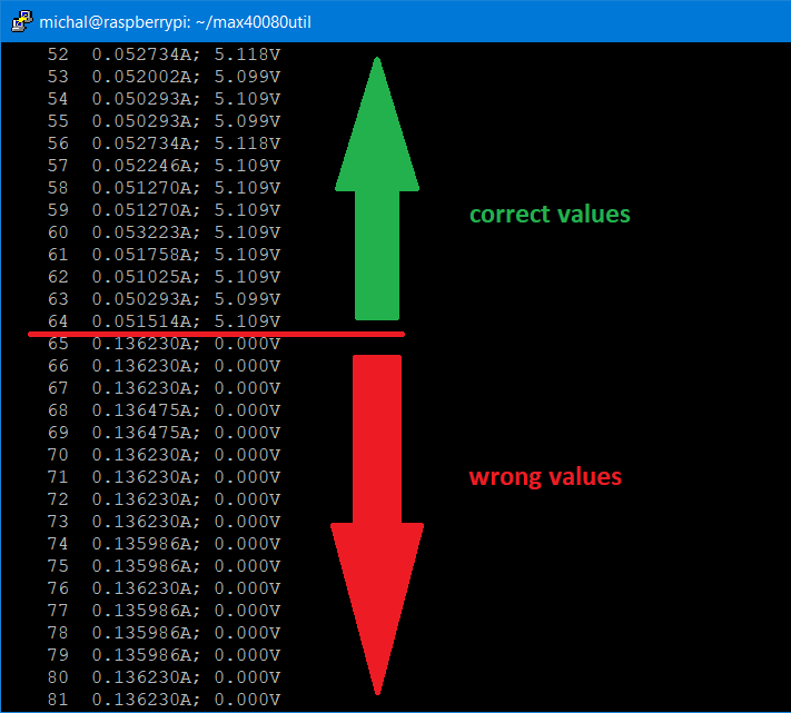
As you can see first 64 samples are correct, but then something strange happened. If I run command multiple time boundaries when sensor started providing invalid samples marked as valid is always at 64th sample (note that 64 is capacity of FIFO). Interestingly when I disabled roll-over feature everything worked well again. Roll-over is good feature which suits use case of most CLI utility use cases, but this issue prevented me to enable it in utility. It is commend now.
CLI Utility Internals
For further explanation it is good to know how does CLI utility works. CLI utility after start parse command line arguments and prepare configuration structure which is than used for writing into Configuration and FIFO_Configuration registers. After configuring sensor, CLI utility flushes all previous data from FIFO and then cleanup all interrupt flags. CLI utility generally do not use interrupt flags, but clearing is important for detection of FIFO overflow at the end of collection of samples. After it clears interrupt flags, it immediately starts reading from Measurement register (Current_Measurement, Voltage_Measurement or Current_Voltage_Measurement depending on configuration). After it receives value from sensor it checks if Data Valid bit is set. When it is set, then CLI utility prints sample. When it is not set, then it means that utility attempted to read sample when there were no sample in the FIFO yet. After required number of samples (-n parameter) is collected, then utility stops collecting samples and reads interrupt flags to check if FIFO overflow occurred anytime when collecting samples. Finally, utility reconfigure sensor to standby mode.
Further investigation
I tried to investigate issue furthermore. Note that at development time I was not sure if this is issue is caused by some bug in my code or sensor really provided this wrong data. I patched internals of my C library and added debug printing of all data received from sensor including data without valid bit set. These printing are marked with x at beginning on following screenshot. Samples with valid bit set are samples beginning with 8. Samples starting with 0 are samples received when there were no sample in the FIFO (without valid bit set). As you can see on the following screenshot after receiving 64th sample something very interesting happened and when preparing 65th sample MAX40080 shifted voltage value 0x022D to the right and marked this sample as valid.
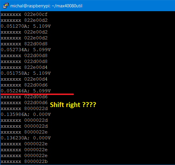
This resolved mystery where did invalid current values come from – It is voltage about 5V improperly interpreted as a current.
I tried some other experiment and found that this happens only when sampling both current and voltage. If I configured sensor to sample only current or only voltage, roll-over mode worked well.
I searched over the datasheet, and I did not find any restriction on using roll-over mode when sensor is configured for storing both current and voltage, so I decided to contact Maxim support and ask them about it. In fact, this was my 7th support request regarding MAX40080 on Maxim support. Maxim support works well and can help you. This is significantly different from support of my internet service provider which generally looks like “Did you tried turn it off and on?”. In previous tickets I reported some mistakes in datasheet (all were accepted. Maxim is working on new revision of datasheet but they did not publish them within contest period) and I asked about Flush Fifo bit behaviour which I described in my 4th blog. 7th case regarding this issue is not closed yet as of end of this contest, but Maxim Application Engineer navigated me to test some other test with inserting delay between readings. CLI utility attest to read data from sensor as fast as possible (and ignore possible readings when no data are prepared yet). For experiment I converted setup to MCU for being able to more precisely control timings of transactions and I tried to interleave sample readings with delay. When I set delay to similar time like period of sample rate divided by configured digital filter, then I was seeing another interesting behaviour (I added 3 columns with values to the printing. They are values of configurations and status register after reading sample, but they are not important now):
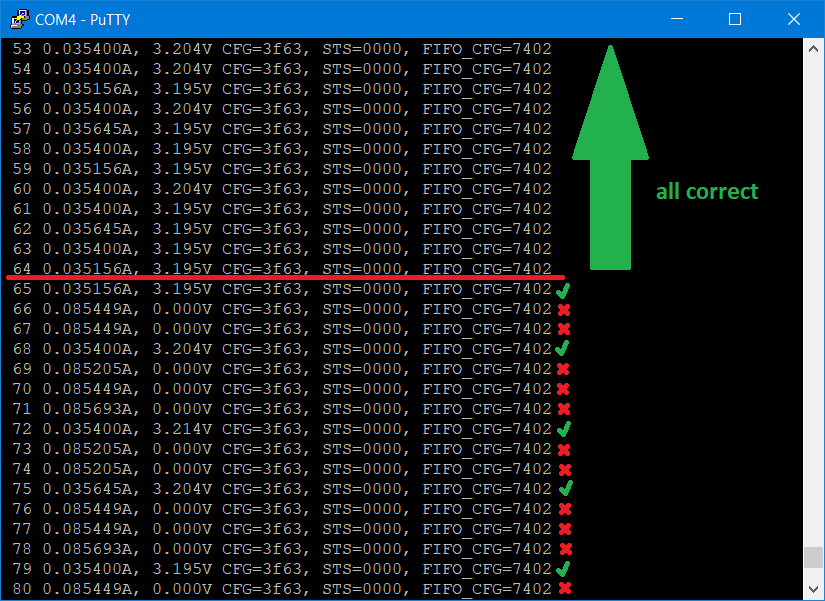
If I increased delay to time slightly more than is sampling period, then I received all samples correct. If I decreased it below, I was received only 64 samples valid, then all were incorrect and finally If I set delay to value similar to sampling period, then some of them was wrong and some of them was correct (higher delay results to fewer wrong samples)
Workaround
To summarize issue happens when both following points apply (when some of them is not satisfied, then sensor works well).
- Collecting both current and voltage
- FIFO roll over feature enabled in FIFO_Configuration register
Then you need to prevent reading samples from FIFO when there are no data. There are at least two ways how to ensure this:
- Read Status register and wait until number of available samples became non-zero (and check for overflow flag, because number of available samples is zero also when FIFO is full)
- Use FIFO overflow warning set to 1 sample and then sensor assert interrupt when new sample become available in FIFO
Maxim support is still investigating the issue, maybe they find some better workaround with knowhow of internal details. To me it looks like wrongly implemented digital logic which is responsible for interleaving voltage and current. This is description from datasheet:
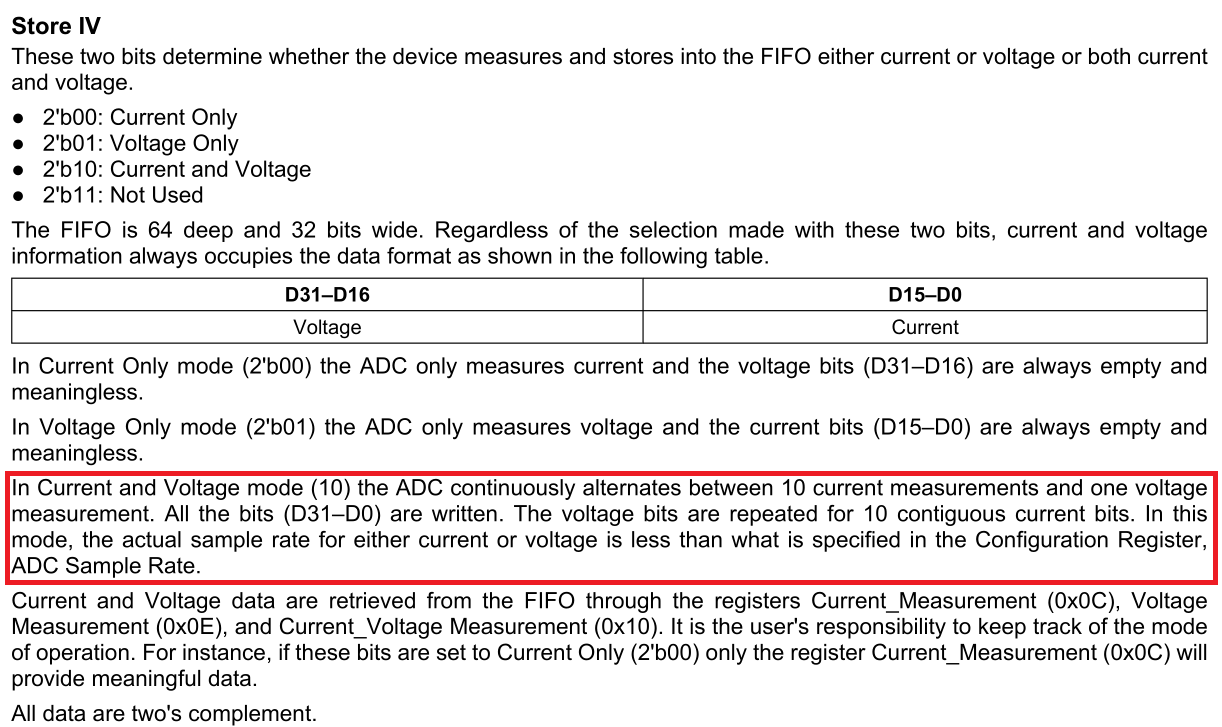
I think that when roll-over mode is enabled, then logic described above marks sample as valid sooner than it is really valid. But without knowhow of chip internals, it is hard to estimate what really happened inside chip.
Last words
Thank you for your attention and reading this blog post. In this blog post I described issue which I was facing when experimenting with MAX40080 CSA sensor. Contest is ending soon, and I will very soon post my summary of all my experiments, projects and what I have learnt and some other closing words. Stay tuned. Similarly, to all my previous blog post I welcome any feedback. Feel free to comment below.
Next blog: Blog #14: Experimenting with Overvoltage Detection
