


What is a Current sense amplifier?
The simplest technique for measuring current is to insert a small resistor, also called a current shunt, in series with the current to be measured. The voltage across the current sense resistor is measured, and the current is computed using Ohm’s Law based on the known value of the resistor. This method has the advantage of simplicity, low cost, and linearity. As the current measurement is based on calculating the voltage drop across shunt resistors used as current sensors the accuracy of the measurement depends on the accuracy of the resistor. So, the selection and placement of these shunts and the associated current sense amplifiers are critical to proper power distribution and efficiency.
A current sense amplifier is a special purpose integrated circuit differential amplifier that is designed to sense the voltage developed across a current shunt and output a voltage proportional to the measured current. The voltage across the current sense resistor is typically in the range of 1 to 100 millivolts, but may ride on the nominal bus voltage potential. The CSA is designed to have a high common-mode rejection ratio (CMRR) to eliminate the bus voltage from the output. These devices are designed to handle common-mode voltages in excess of their own supply voltage.
The choice of the current sense resistor must include attention to the resistor’s accuracy, temperature coefficient of resistance (TCR), and power rating. The resistance value determines the voltage drop across it for a given current value. It also determines the power dissipated by the sense resistor. Generally, the sense resistor’s value is a fraction of an ohm. Specialized resistors are available for this application. These resistors use metal elements in the form of plates, foil or film, or deposited thin or thick-film hybrid elements.
Difference between Current Sense Amplifier and Normal Amplifier
Normal amplifiers and current sense amplifiers have different specifications and they are made for specific things. There are many types of Op-Amps, you can read this article to know the popular Op-Amps IC and their applications. Normal amplifiers could not amplify a very small amount of voltage and have low CMRR. On the other hand, precision current-sense amplifiers could detect and amplify a very small amount of voltages as well as the CMRR is relatively high.
For the normal differential amplifiers or standard operational amplifiers, the power source is connected between two power supply rails (Vcc and Vee) and the amplifiers can only operate on the signals that lie behind the power rails or have common ground paths. An outside voltage of the used power rail could trigger the internal ESD protection diodes if an external voltage is applied to the input pin of the standard amplifier and could cause a large current to flow. But, current sense amplifiers are designed in a way that despite the low-voltage power rail (such as Vcc = 3.3 V and V = 0V), the amplifier can withstand a much higher pin voltage than the supplied Vcc. The amplifiers use an excellent power path protocol for their operation. Whenever the input voltage is lower than the VCC, the amplifier changes its input supply and gets powered by the input voltages.
How does a Current Sense Amplifier Work?
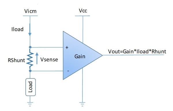
The working principle of a current sensing amplifier is based on Ohm's law. When load current flows through a shunt resistor (Rshunt) present on inputs, it generates a voltage drop called VSENSE. This voltage is generally small to limit power dissipation losses. VSENSE is then amplified with an internal current sense amplifier. The resulting output voltage (VOUT) is a voltage that is proportional to the Ioad current. It can then be processed with an ADC (analog-to-digital converter).
The MAX40080 Current Sense Amplifier
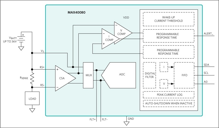
The MAX40080 is a high-precision, fast-response, bi-directional current-sense amplifier with digital output and a very wide input common-mode range from -0.1V (ground sensing) to 36V.
The device features an ultra-low 5μV input offset voltage and a very low 0.2% gain error. The low input offset voltage is especially important because it allows using a small sense resistor, thus saving power dissipation, but at the same time not compromising the measurement accuracy. The device also features a programmable input sensing range between ±10mV and ±50mV (or programmable input gain between 125V/V and 25V/V) which is very useful to enhance accuracy at low current.
The device includes an analog-to-digital converter with a programmable sample rate and 12-bit resolution (13-bit including sign bit for current measurement) and features an I2C compliant and SMBus compatible interface.
The device features a wake-up current threshold and auto-shutdown mode when the I2C is inactive. Both these features are designed to minimize power consumption.
The device is available in a small 12-pin WLP (and also a 12-pin TDFN) and is specified over the -40°C to +125°C extended operating temperature range.
Current 6 Click
Current 6 Click is a compact add-on board providing a precise and accurate current sensing solution. This board features the MAX40080, a current-sense amplifier from Analog Devices discussed above. This Click board delivers higher performance to industrial control and automation applications, load and power supplies monitoring, telecom equipment, and many more.
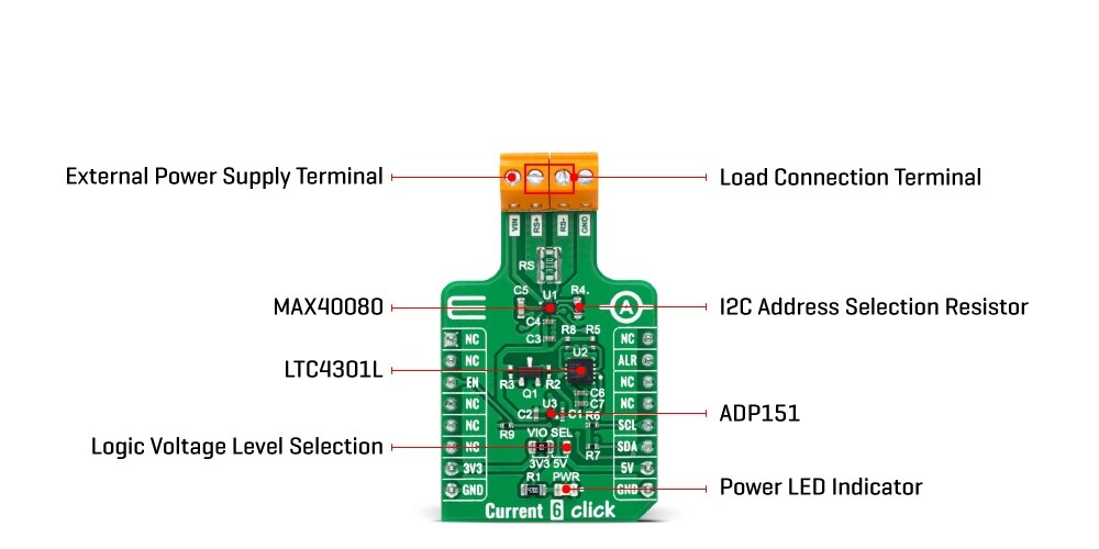
Current 6 Click as its foundation uses the MAX40080, a high-precision, fast sample-rate digital current-sense amplifier from Analog Devices. The MAX40080 measures current and common-mode voltage ranging from -0.1V to 36V and converts the data into digital form through an I2C-compatible two-wire serial interface allowing access to conversion results. Also, setting the input voltage sense using the I2C register, ±50mV or ±10mV, will allow one to select two measuring ranges from 0A to 1A or from 0A to 5A.
This Click board communicates with MCU using the standard I2C 2-Wire interface for configuring and checking the device's status. Standard I2C commands allow reading the data and configuring other operating characteristics. While reading the current/voltage registers, any measured current and voltage changes are ignored until the read is completed. The current/voltage register is updated for the new measurement upon completion of the read operation.
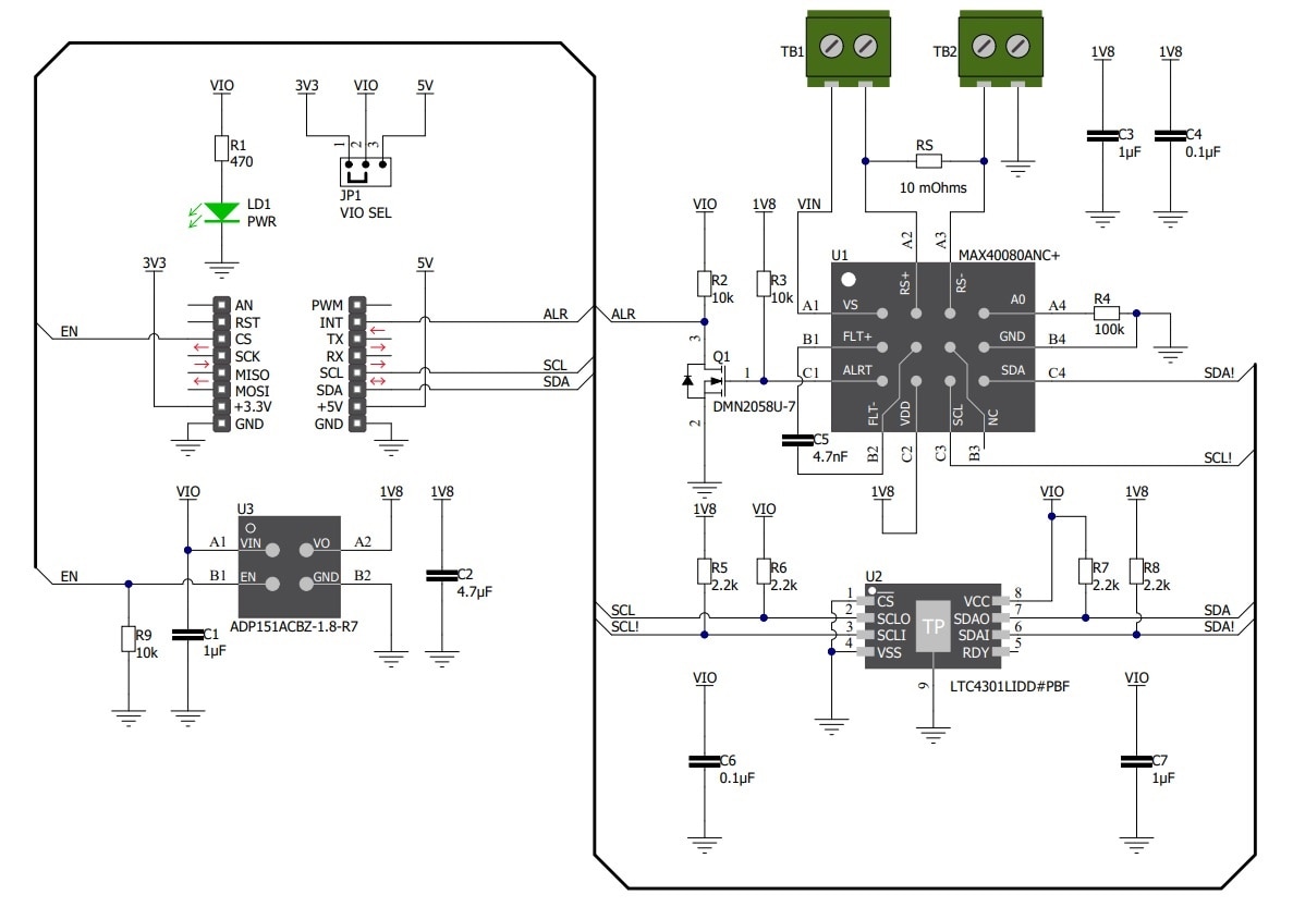
Schematic for Current 6 Click
Getting Started with Current 6 Click
I received a Pi 3 click shield/Expansion board and current 6 click for free from Element14 as part of this design challenge but unfortunately, I did not receive Raspberry Pi 3. I checked the user manual for Pi 3 click shield and found that it works with Raspberry Pi 2 B also. Fortunately, I have a Pi 2 in my parts bag. So, In this blog, I am going to use the current sense 6 click with my Raspberry Pi 2. MikroElektronika does not provide any library for the current sense 6 click for python or Raspberry Pi environment. So, I will use python library written by misaz. The library is here (https://github.com/misaz/MAX40080-PythonLibrary). Mr. misaz written an excellent blog on getting started with the current 6 click with Raspberry pi. You can find it here.
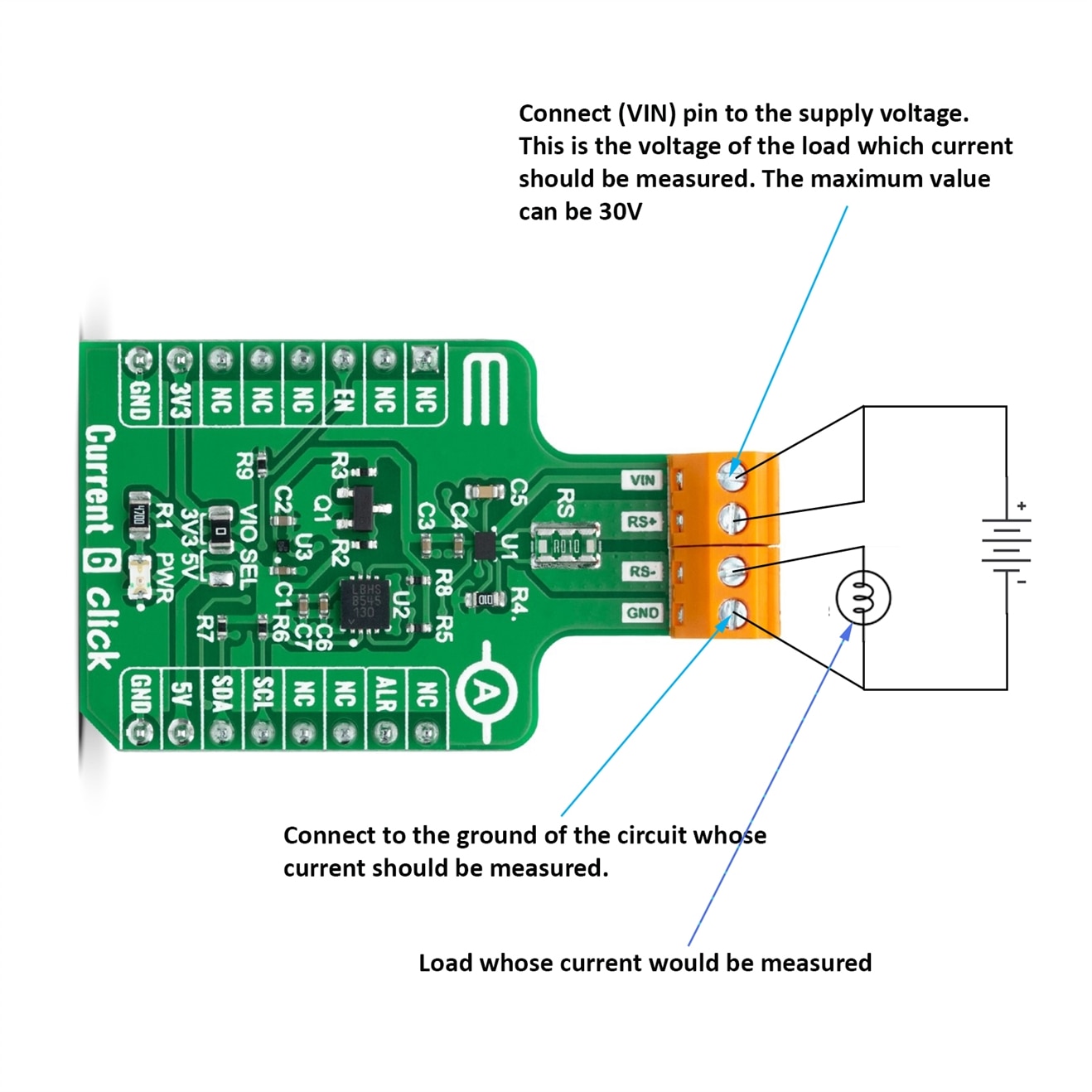
The connection for measuring current will be like in the following image.
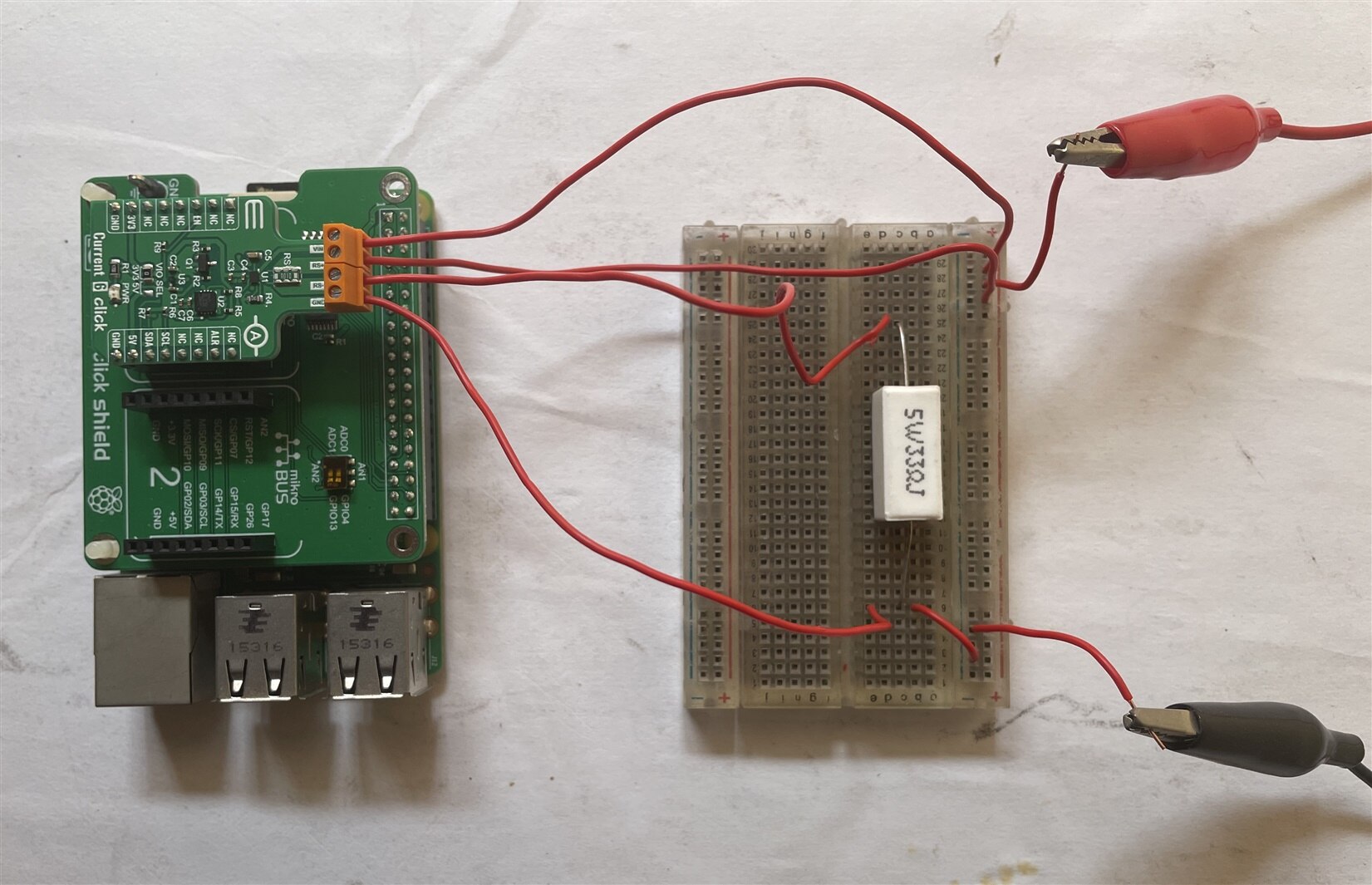
For testing purposes, I am using a 5W, 33ohm resistor with a power supply. I used high-current jumper wires for connecting the sensor to the measuring circuit. If your jumper wires can not handle much current you can get the wrong value for a significant voltage drop in the jumper wire. It is very important for high current measurement. Traditional breadboard jumper wires can handle around 1 A without a significant voltage drop.
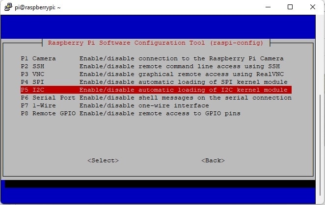
Now, enable i2c from the raspberry pi configuration. You can use the following command in the terminal to go to the configuration option.
sudo raspi-config
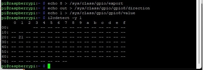
The current 6 click board should be enabled by providing high signal to the enable pin that is connected to CS pin of the mikroBUS socket. If you plug the current 6 click board into socket 1 of the expansion shield the CS pin will be connected to the GPIO 8 of the Raspberry Pi. So, you have to make this pin high to enable the current 6 click. The GPIO 8 Pin can be set as HIGH using the echo command from the terminal:
echo 8 > /sys/class/gpio/export
echo out > /sys/class/gpio/gpio8/direction
echo 1 > /sys/class/gpio/gpio8/value
You have to use GPIO 7 instead of 8 if you use 2nd slot.
Now you can detect your device using the following command from the terminal
i2cdetect -y 1
If you can detect your i2c device successfully then download the following two python libraries in your Pi. The first one is for i2c communication and the second one is for making the plot.
pip3 install smbus
pip3 install matplotlib
After downloading the above libraries create a python file and add the following code. You can create the file directly in your Raspberry Pi or if you access Raspberry Pi using a serial terminal it is better to create the python file on your pc and then transfer the file to the raspberry pi using any FTP client like WinSCP. I created the python file named current_plot.py.
import RPi.GPIO as GPIO
import smbus
import matplotlib.pyplot as plt
import time
GPIO.setwarnings(False)
GPIO.setmode(GPIO.BOARD)
GPIO.setup(8,GPIO.OUT)
GPIO.output(8,GPIO.HIGH)
max40080_addr = 0x21
bus = smbus.SMBus(1)
# set mode from standby to active
bus.write_i2c_block_data(max40080_addr, 0x00, [0x63, 0x00, 0x7D])
time.sleep(.1)
# check configuration
value = bus.read_i2c_block_data(max40080_addr, 0x00, 3)
print("cfg reg =", value)
# read measurement
value = bus.read_i2c_block_data(max40080_addr, 0x0C, 3)
print("data reg =", value)
measurements = []
for i in range(100):
value = bus.read_i2c_block_data(max40080_addr, 0x0C, 3)
filtered_flag = ((value[1] & 0x7F) << 8) | value[0]
sign_ext = ((filtered_flag & 0x4000) << 1) | filtered_flag
bytes_after = [sign_ext & 0xFF, (sign_ext & 0xFF00) >> 8]
measured_value = int.from_bytes(bytes_after, "little", signed="True")
measurements.append(measured_value)
time.sleep(0.001)
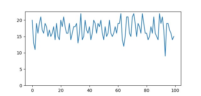
print("Average:", sum(measurements) / len(measurements))
plt.plot(measurements)
plt.ylim(ymin=0)
plt.show()
Now, run the python file using the following command:
python3 current_plot.py
You will see a graph that looks like as the image below.
In the next blog, I will measure the high side and low side current for a circuit and compare the result.
-

misaz
-
Cancel
-
Vote Up
0
Vote Down
-
-
Sign in to reply
-
More
-
Cancel
-

taifur
in reply to misaz
-
Cancel
-
Vote Up
0
Vote Down
-
-
Sign in to reply
-
More
-
Cancel
Comment-

taifur
in reply to misaz
-
Cancel
-
Vote Up
0
Vote Down
-
-
Sign in to reply
-
More
-
Cancel
Children