


High-side & Low-side Sensing
There are two locations in a circuit the current shunt is commonly placed for current measurements. The first location is between the power supply and the load. This measurement method is referred to as high-side sensing. The second location is between the load and the ground. This method for sensing current is referred to as low-side current sensing. The figure below illustrates the two locations of current sensing in a circuit.

There are advantages and disadvantages of doing either measurement. One of the advantages of low-side current measurement is the common-mode voltage at the measurement inputs for the current sense amplifier is near zero. This makes it easier to design application circuits or select devices for this measurement. Since the voltages seen by the current sensing circuit are near the ground, this is the preferred method for measuring current when dealing with very high voltages, or in applications where the supply voltage may be prone to spikes or surges. The immunity to high voltage spikes and ability to measure currents in high-voltage systems make low-side current measurement popular in many automotive, industrial, and telecommunication applications. The measure disadvantage of low-side current measurement is that the voltage drop across the sense resistor appears as a difference between the supply ground and the load/system ground. This can be an issue if other circuits are referenced to the supply ground. To minimize this issue, reference all circuits that have interaction to the same ground. Reducing the value of the current sense resistor helps minimize any ground shifts.
High-side current measurements have two key advantages over low-side measurements. First, it's easy to detect a short circuit originating from within the load to ground because the resulting short circuit current will flow through the current shunt resistor, developing a voltage across it. Second, this measurement technique is not ground referenced so differential ground voltages developed by high currents flowing through the ground plane will not affect the measurement. However, it's still a good idea to carefully place the sensing ground reference connection close to the amplifier's ground. The main disadvantage of high side current sensing is, that it requires the current sense amplifier have high common-mode rejection because the small voltage developed across the current sense resistor rides just below the load supply voltage.
In this blog, I will measure the current on both sides and compare the result and show whether the sensing value changes for changing the side or is there any effect of the sensing side on measurement accuracy.
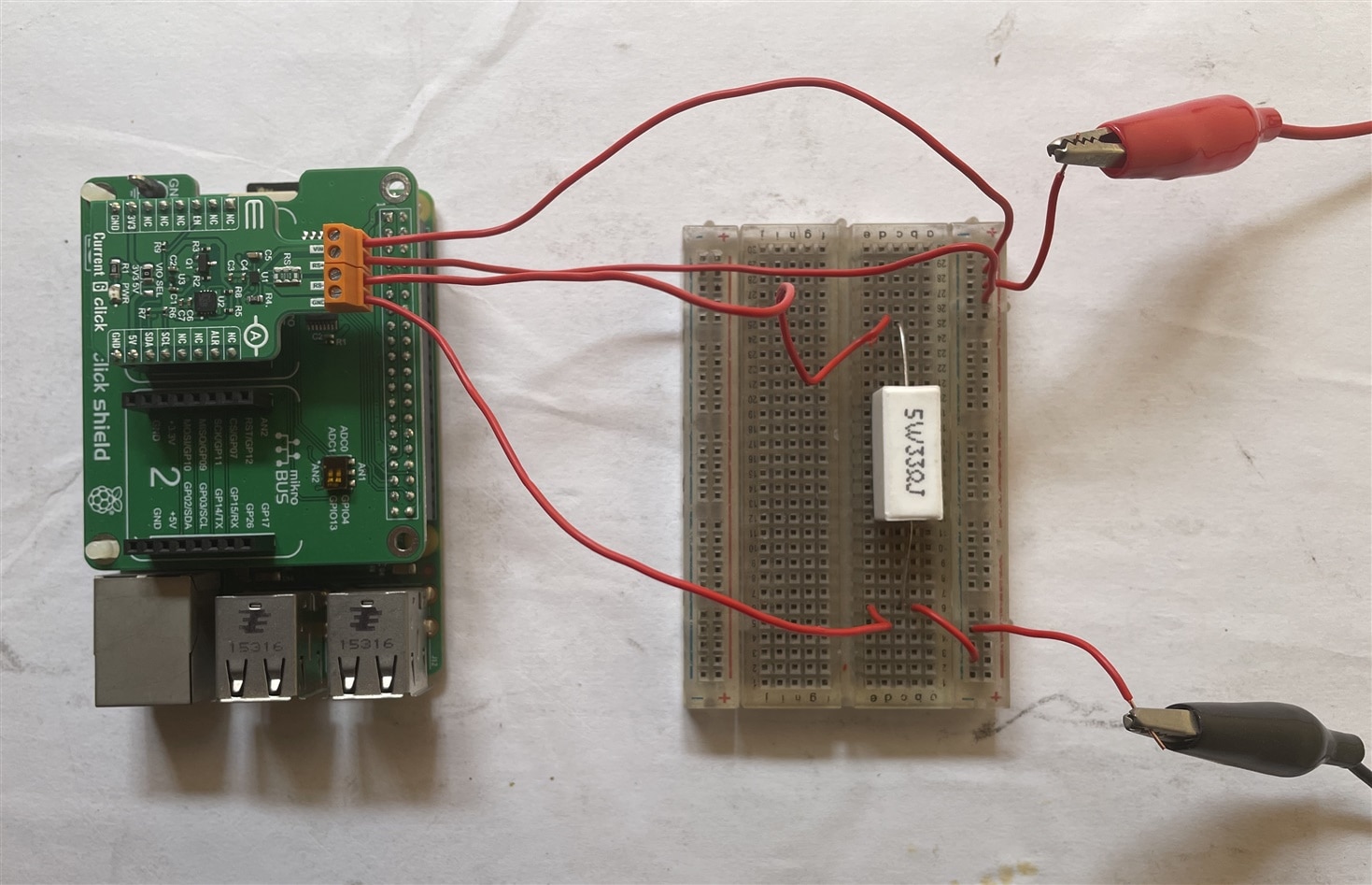
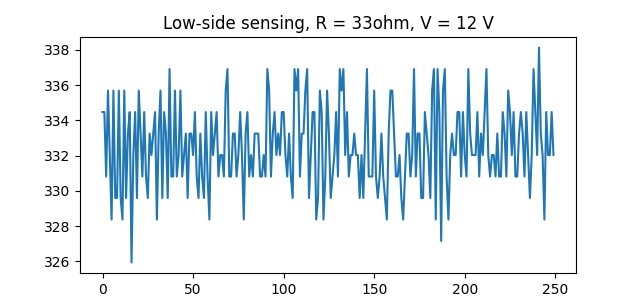
First I will measure the high side current through a 33ohm resistor. The resistor is powered from a 12 V power supply. Following image shows the circuit connection. According to ohm law the current through the resistor is 12/33 = 363mA. Let measure the current using the current 6 click.
For the current measurement, I used MAX40080 Python Library by misaz and the details are available here. I wrote the code for reading 250 samples and plotting a graph using the measured samples.
This is the python code:
from max40080 import MAX40080
import matplotlib.pyplot as plt
import time

max = MAX40080()
max.configure(sample_rate_khz=15, digital_filter=1, measure_current=True, measure_voltage=False)

def read_plot_current():
    measurements = []
    for i in range(250):
        value = max.read_current() * 1000
        measurements.append(value)
        time.sleep(0.001)
    print("Average(high-side, 250 samples):", (sum(measurements) / len(measurements)), " mA")
    plt.plot(measurements)
    plt.title('Low-side current sensing')
    plt.show()

read_plot_current()
After running the code the following graph was generated for high side setup.
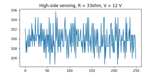
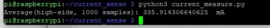
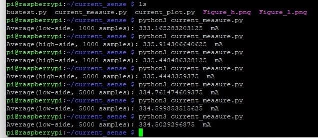
The average current for 1000 samples was 335.914mA which is closed to the calculated value.
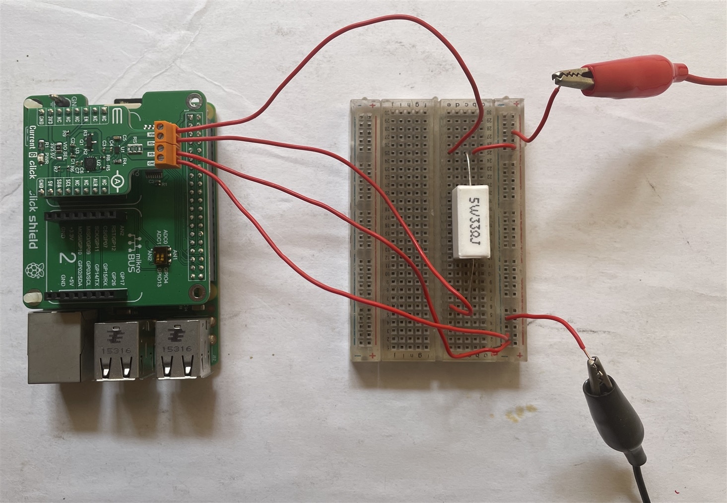
After measuring the high side current I changed the circuit as follows for low side sensing. The voltage was the same as the previous setup.
I got the following result which is very close to the previous result. It seems the value does not change for high side or low side measurements which is very logical.
The average current for 1000 samples was 333.16 which is around 2 mA different from the previous measurement.

To remove the confusion from my mind I recalculate the average current for 5000 samples on the high and low side again. Again I noticed that for low side sensing average current is slightly lower. I have no explanation for this at this time!
Low current sensing
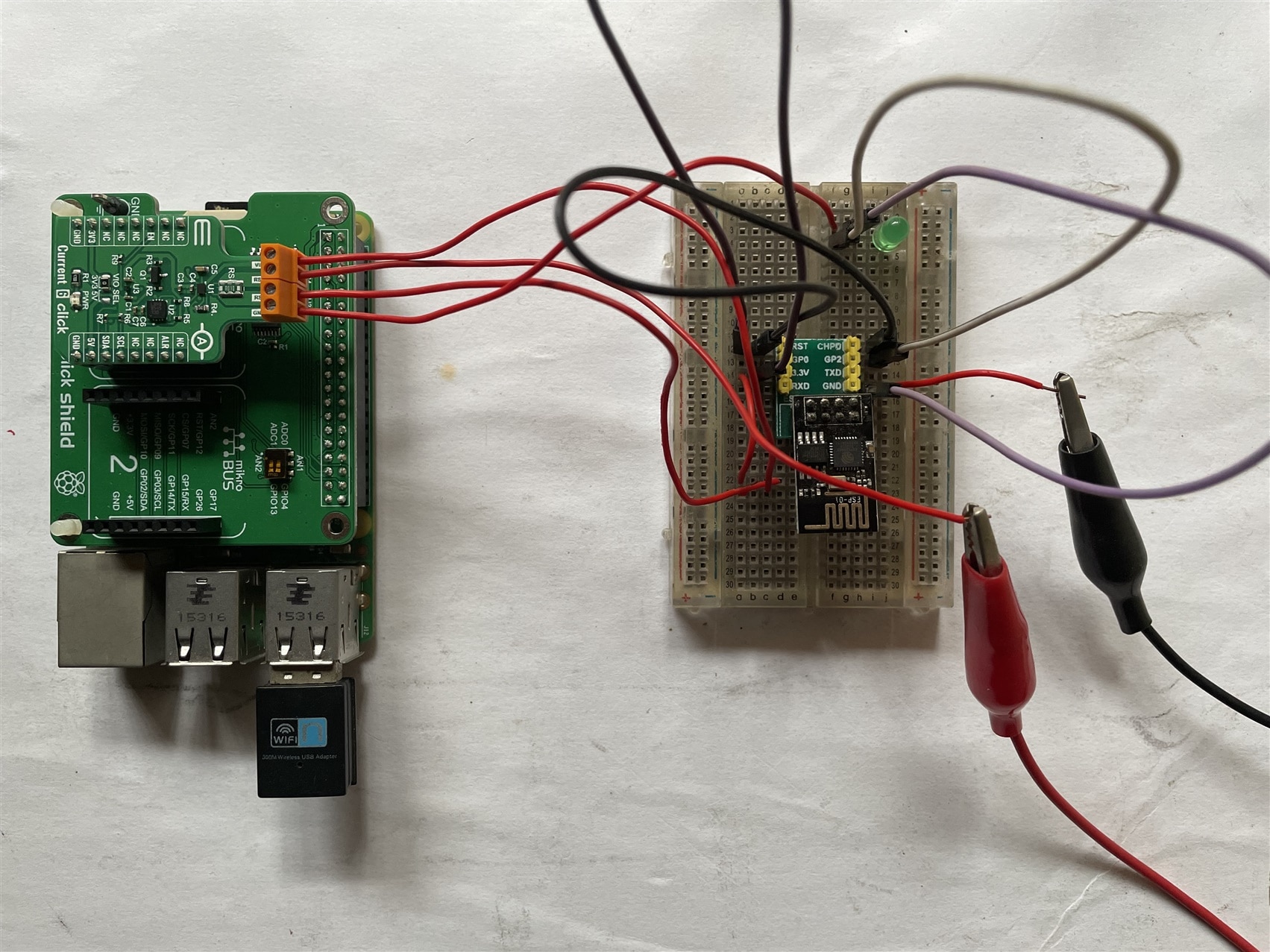
After measuring the current on the high side and low side I tried to measure the current consumption of an ESP8266-01 module. I did the experiment in different situations. First I tried to measure the current-sinking by ESP8266-01 only for powering an LED. WiFi was disabled and esp was powered from 3.3V supply. This is the circuit connection:
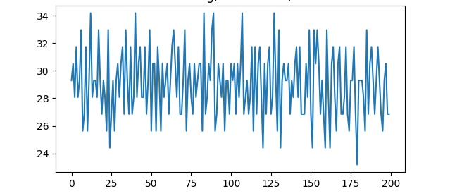
When GPIO 2 LED was on I got the following graph. The average current was around 29mA.
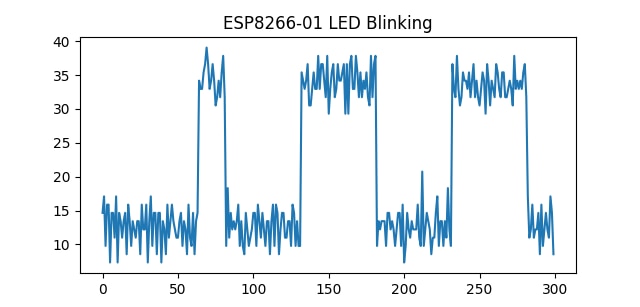
Then I program the ESP8266-01 to blink an LED every 100mS and I got the following graph. The graph is very logical and it is clear that when LED is ON the current is around 20mA higher.
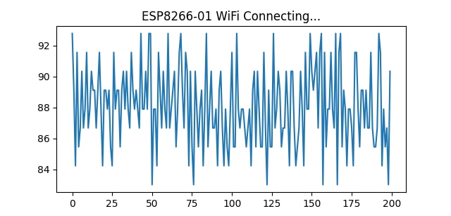
Then I tried to measure the current when esp is connecting to the wifi. The following graph was generated.
Finally, I tried to measure the deep sleep current for ESP8266-01 which is around 20 uA. But the measurement result made me frustrated. It shows a negative measurement for deep sleep.
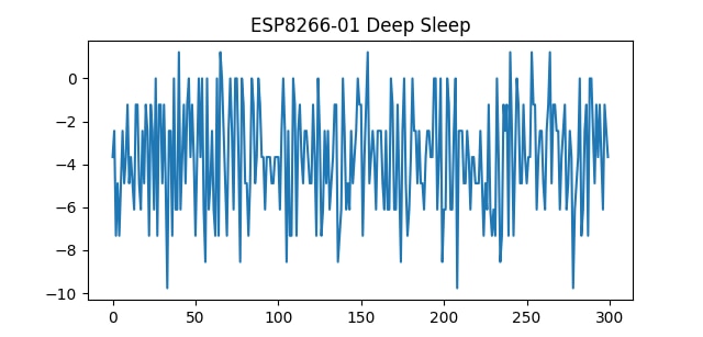
In the misaz library, the input range was set to 50mV and this is not configurable. So, I manually configure the input range to 10mV but no such improvement was observed. The result follows when the input range is 10mV.
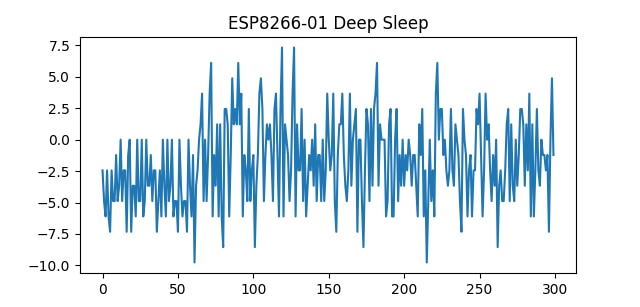
So, the 10mohm shunt resistor is not enough for very low current measurement when the current value is less than mA. It can be tested with a higher shunt.
-

michaelkellett
-
Cancel
-
Vote Up
0
Vote Down
-
-
Sign in to reply
-
More
-
Cancel
Comment-

michaelkellett
-
Cancel
-
Vote Up
0
Vote Down
-
-
Sign in to reply
-
More
-
Cancel
Children