Hello everyone. I welcome you to my 4th blog post as part of Experimenting with Current Sense Amplifiers Design Challenge. In my previous blog post #1, #2 and #3 I described my experiment plans as part of contest, and shown basic usage of MAX40080 Current Sense Amplifier sensor. In this blog post I will introduce my setup which I will use for developing and debugging my own library targeting MAX40080 sensor and I will use it in some of my experiments which I described in 1st blog post.
MAX32625 Microcontroller and MAX32625PICO board
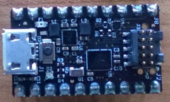
In this and some future experiments I will use MAX32625 Microcontroller. It’s ARM Cortex-M4 microcontroller clocked up to 96 MHz. This microcontroller is very tiny and is almost impossible to solder it in home environment, so I will use MAX32625PICO board. MAX32625PICO is mainly designed as DAPLink debugger for debugging other board. But board of course can be programmed and used as general-purpose microcontroller. I will use it in this way. Maxim bundles this board with some evaluation kits. In fact, this was the way how did I received it. But it is nice and interesting board for any other general purpose use case. One of very interesting feature is selectable 1.8V or 3.3V logic on GPIO ports. MAX32625 PICO features onboard PMIC which creates 1.8, 3.3 and 5V voltages and I will use all of them in some way. If you are interested in mode details about MAX32625 MCU or PICO board, you can read my blog post Review of MAX32625 MCU and MAX32625PICO board which I wrote as part of previous RoadTest. MAX32625PICO board looks as follows:

I will use this microcontroller for controlling MAX40080 and some other peripherals depending on need of my future experiment. Because there is no library for using MAX40080 CSA with MAX32625 MCU I had two options:
- Port already existing library
- Write my own library
I chose the second option. Writing my own library allows me to learn all details about the chip under test and this is reason why I like creating my own libraries for chips.
Development setup
For developing I will use USB-to-JTAG converter. I will use board containing FTDI FT223HQ chip as a debugger. It is similar chip to chip used in Olimex debugging probes which Maxim bundles with some of their Evaluation Kits and it is supported by Maxim toolchain. I need to use level shifter because FTDI Chip works with 3.3V levels and MAX32625 SWD debug interface is limited to 1.8V.
Next part is of course MikroE Current 6 Click Board featuring MAX40080 CSA. I will place this board on the breadboard and power it from 3.3V rail of MAX32625 board. While MAX40080 is naturally 1.8V chip, MikroE Click board contains level shifter and power circuit that requires power and logic signals in range 2.7V to 5.5V. So, I will use 3.3V rail of MAX32625PICO board for powering it.
Measured circuit depends on experiment. For library development I used simple resistor powered by 5V rail of MAX32625PICO board.
Last peripheral which I will use in the initial setup is USB-to-UART converter for receiving messages from my firmware running on MAX32625 MCU. It also works on 3.3V level.
To summarize, I will use connection visualised by following simplified block diagram:

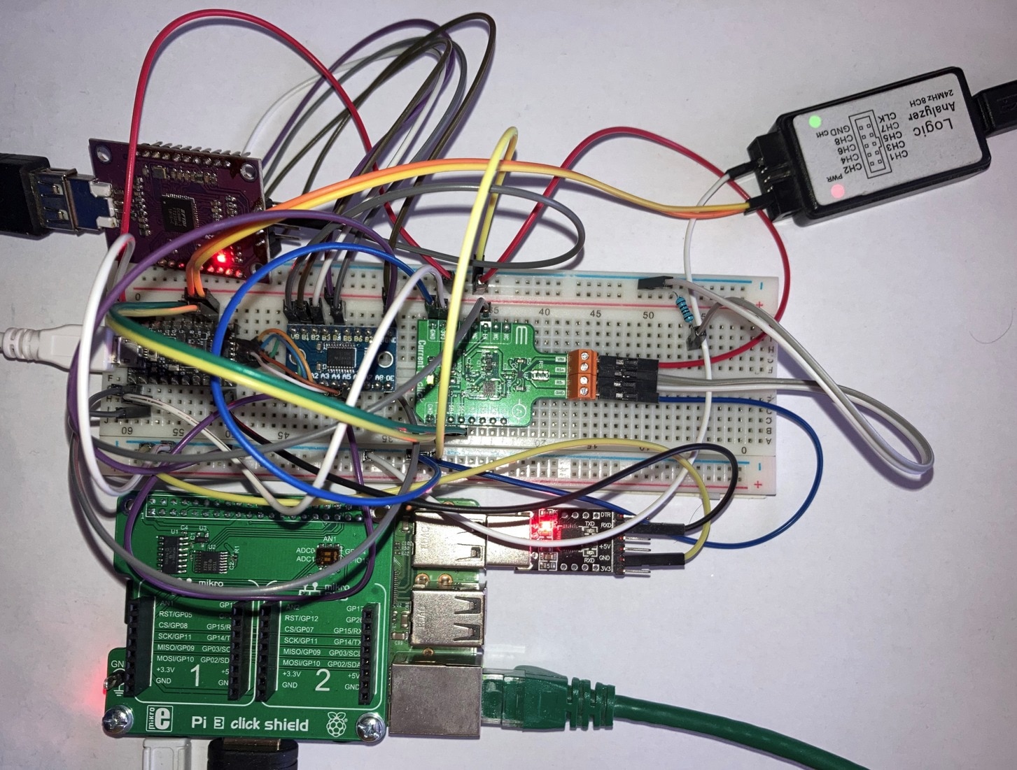
I connected all these peripheral on the breadboard and in real life it looks like this:

As you can see it is lot of wires. It is mainly caused by connecting multiple power rails, and many wires connects grounds of every peripheral. On the breadboard you can see (from left to right) MAX32625PICO, Level Shifter, Click Board featuring MAX40080 CSA and finally there are resistor. Above the breadboard there is board with FTDI USB-to-JTAG converter and logic analyser for debugging at right side. Because I utilized all USB ports of my computer, I used Raspberry Pi for connecting USB-to-UART converter.
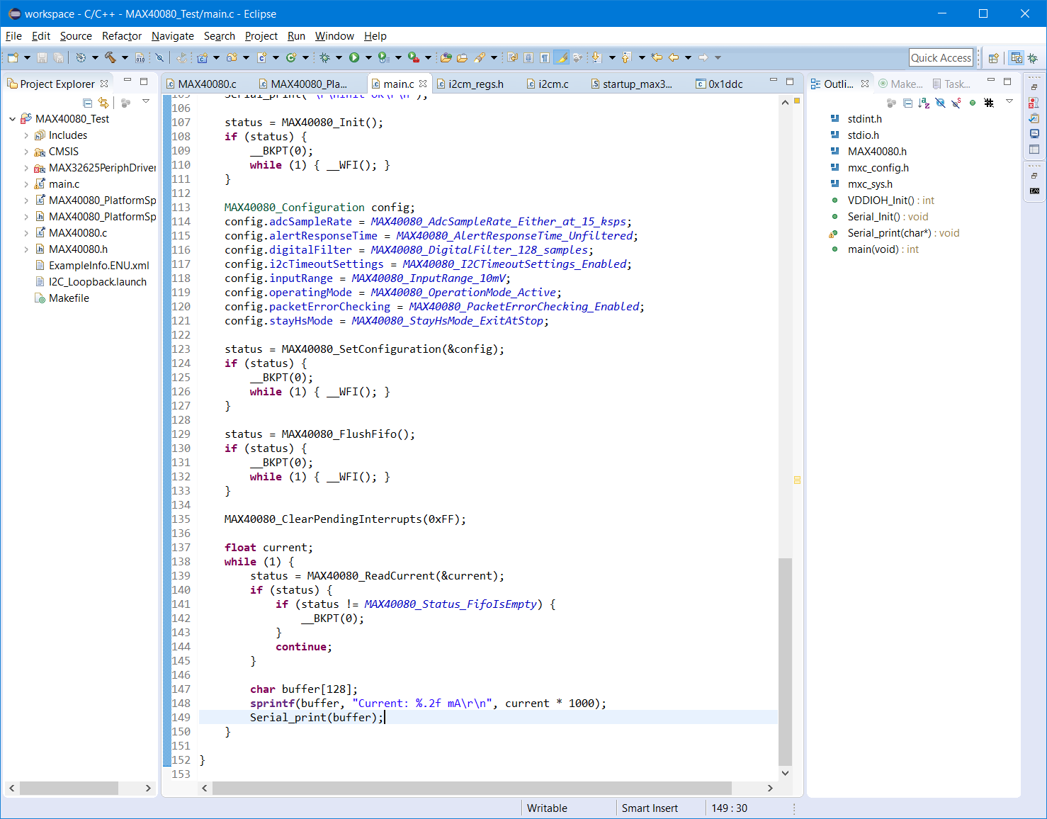
After connecting it (and troubleshooting it) I implemented I2C communication using driver from MAX32625 SDK and wrote simple program. For developing I used Eclipse IDE installed as part of Maxim MCU SDKs. IDE is standard Eclipse:

First code
The first example code using my library is simple code which configures MAX40080 chip and collects measurements. It enables some advanced features like digital filtering and flushes FIFO for clearing previous samples (Sensor is not reseted with MCU and it works at the background while MCU is in reset state). Then I read and prints measured current to the UART terminal. Main function of my first code looks as follows:
int main(void) {
MAX40080_Status status;
int iStatus;
iStatus = VDDIOH_Init();
if (iStatus) {
__BKPT(0);
while (1) { __WFI(); }
}
Serial_Init();
Serial_print("\r\nInit OK\r\n");
status = MAX40080_Init();
if (status) {
__BKPT(0);
while (1) { __WFI(); }
}
MAX40080_Configuration config;
config.adcSampleRate = MAX40080_AdcSampleRate_Either_at_15_ksps;
config.alertResponseTime = MAX40080_AlertResponseTime_Unfiltered;
config.digitalFilter = MAX40080_DigitalFilter_128_samples;
config.i2cTimeoutSettings = MAX40080_I2CTimeoutSettings_Enabled;
config.inputRange = MAX40080_InputRange_10mV;
config.operatingMode = MAX40080_OperationMode_Active;
config.packetErrorChecking = MAX40080_PacketErrorChecking_Enabled;
config.stayHsMode = MAX40080_StayHsMode_ExitAtStop;
status = MAX40080_SetConfiguration(&config);
if (status) {
__BKPT(0);
while (1) { __WFI(); }
}
status = MAX40080_FlushFifo();
if (status) {
__BKPT(0);
while (1) { __WFI(); }
}
MAX40080_ClearPendingInterrupts(0xFF);
float current;
while (1) {
status = MAX40080_ReadCurrent(¤t);
if (status) {
if (status != MAX40080_Status_FifoIsEmpty) {
__BKPT(0);
}
continue;
}
char buffer[128];
sprintf(buffer, "Current: %.2f mA\r\n", current * 1000);
Serial_print(buffer);
}
}
This code relies on my Library and some other helper functions. I will post details about my Library in later blog post after I properly test it. Results from my first code was received on terminal:

You can see that measurements are very stable and noise which we have seen in previous examples is gone. It is caused by digital filter (averaging) which I enabled in this experiment. Measured values are correct. I use 100ohm resistor powered by 5V rail but 5V rail from USB I measured about 4.6V. So, from ohm law 4.6 / 100 is about 46 mA.
First thoughts
In previous showcase you have seen my library. Of course, it was not as seamless as I described it and I faced some issues when developing. I found two strange things related FIFO which I want to share because it may help other challengers. They are not bugs but they can cost you lot of time if you do not expect them.
FIFO Flush Bit is not automatically cleared even it is read as zero
MAX40080 has 64 cell FIFO for storing measured values. FIFO can be configured using register. Its structure is following:

There are two strange things related to usage of FIFO which are not clear from documentation, and they cost me about 50 minutes of debugging.
The first thing is behaviour of Flush bit. Writing 1 to this bit flushes whole FIFO content. After writing 1 to this bit, I checked that FIFO data count (which can be read from different register) went to zero and it was fine, but I faced another issue. I was unable to collect any samples anymore. I originally wrote my code in a way that I was waiting while FIFO data count is zero, but it did not increase from zero anymore. After some experiments I found that after writing 1 to Flush bit it is mandatory to write zero to this bit again otherwise sensor will permanently flush measured data. Other strange thing is that when you read this register you always receive this bit as zero even it is internally set to one and flushes FIFO at the background. On following screenshot, you can see two transactions. First writes FIFO configuration register at address 0xA to value 0xB400 (B4 means Flush bit is set and Overflow_Warning is set to default value) and the second transaction reads the same register, but outputted value is 0x3400 (Overflow_Warning is the same but Flush bit looks reset to zero by sensor). After these two transactions I was unable to collect samples anymore until I explicitly issued third transaction writing 0x3400 to the register. Then my sensor stars to fill FIFO with data again.

I consider it as a strange behaviour, and it is also not documented anywhere in the datasheet. I asked/reported about it to Maxim technical support, and I received reply that they will check about it, but issue is still in progress.
FIFO Data Count is zero when FIFO contains 64 entries
The second issue which I have faced is that sensor returns number of FIFO data entries as zero when the FIFO is full (and contains 64 entries). It is because field is 6 bits wide and can hold values in rage 0 to 63. When your FIFO has 64 entries, value overflow and you see it as a zero. In this case datasheet mention this issue and also provide help for detecting this issue and implementation workaround:

Summary
In this blog you have seen my circuit and first tests of using MAX40080 by microcontroller instead of Raspberry Pi. You have seen first code using my Library which I will present in more details in future blog post. Next interesting outcome is that enabling averaging can perfectly filter out the noise. And finally, I described two unintuitive behaviours of sensor FIFO which I was facing in experimenting time. Thank you for your patience. I like to hear any feedback regarding my blog posts in comments so feel free to leave any comment bellow.
Status and Future plans
My further experiments which I promised in first blog are still stuck on PCBs. Yesterday OSHpark received them from fab and shipped them to me. I expect receiving them within three weeks. In the meantime, I ordered and received required components.
According to multiple requests I decided making another library written in Python which can be used on Raspberry Pi. It would be simpler library than my library for microcontrollers but allows other challengers to use many features of sensor without need of knowing registers structure, computing CRCs, and so on.
Finally, I got an idea to make Linux CLI utility based on my MCU library which will allow me and other challengers experiment with MAX40080 CSA from command line without any programming required. I will post some details about it soon.
Next blog: Blog #5: My Python and C Libraries are available now


-

embeddedguy
-
Cancel
-
Vote Up
0
Vote Down
-
-
Sign in to reply
-
More
-
Cancel
-

misaz
in reply to embeddedguy
-
Cancel
-
Vote Up
0
Vote Down
-
-
Sign in to reply
-
More
-
Cancel
-

embeddedguy
in reply to misaz
-
Cancel
-
Vote Up
0
Vote Down
-
-
Sign in to reply
-
More
-
Cancel
Comment-

embeddedguy
in reply to misaz
-
Cancel
-
Vote Up
0
Vote Down
-
-
Sign in to reply
-
More
-
Cancel
Children