


In my final post for this build, I'll share my working project and some thoughts I've had along the way.
What did I build?
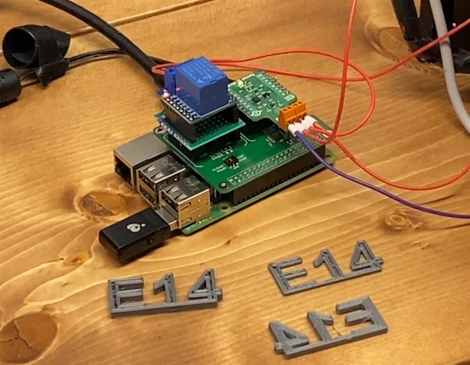 Using the Current6Click current monitoring board mounted on a Pi3 Click Shield, and mounted on a RaspberryPi, I was able to build something which can detect wiring faults. The Current6Click board uses a MAX40080 current sense chip and comes as a ready-to-go expansion board with shunt resistor and other supporting circuitry. The goals were to be able to detect intermittent opens in the wires going to the hot end and heated bed on a 3D printer. Opens and Shorts can also be detected.
You can read my progress in these posts:
- Blog #1 Introduction and goals
- Blog #2 Getting started with the Current6Click
- Blog #3 Troubles resolved talking to chip, but lots more hurdles
- Blog #4 Nearly functionally complete
How does it work?
The MAX40080 can measure both current and voltage at the same time. A 3D printer cycles power on and off to the hot parts to maintain a target temperature. This means that whenever there is voltage available, current should be flowing. My code first sees if there is voltage; then it reads the ADC at about 500 times/second and monitors the current. On the hot end of my printer, we should have about 12 volts and flow about 2.75 amps. If there is a fatigued or damaged wire, there would be a very intermittent open circuit where the MAX40080 can see 12V but current drops to zero. In the case of a short, the current would spike very high very quickly; still at about the 12v level. An open circuit would look the same as the intermittent, but last longer. Most printers these days come with 'thermal runaway monitoring' in software, but some don't; and some aren't turned on by default leaving it up to the user to know and enable the feature. That feature however works by monitoring the temperature feedback and the software's own output to run the heaters. If the thermocouple shows the nozzle getting colder and not heating up when the controller is trying to heat it, this causes the alarm.
However, in the case of a fatigued wire or loose connection, this would never be caught. Unfortunately, these bad connections are a potential fire risk as more current has to flow through the few remaining strands of copper or the little bit of connector that is touching a terminal. This causes excessive heat buildup which can cause lots of other issues. Short of adding a thermal camera, there really isn't a way to directly look for poor connections. Imaging a printer that's been in service for a few years and 1000's of hours. There could be certain parts of the travel that stress the wires just that little bit more and break it down.
I've had this idea rolling around in my head to detect a wiring fault on these large current-carrying wires in a printer for a while. I had originally though of doing it via discrete components - a traditional op-amp & shunt resistor; running the voltage through a comparator and AND'ing with the 12V signal. When the voltage rises above the level set in the comparator, it would open a relay to signal a fault. This MAX40080 can read very fast and still seems to do the trick just fine, and I found that it was pretty easy in software to tweak values and setpoints and add other integration like MQTT.
The latest updates to get this puppy running
My previous post showed the system nearly complete. The RaspberryPi was talking to the Click board and getting measurements. I was able to detect shorts, opens, and broken wires. I was using an external relay on an Arduino to cycle ON/OFF the 12V feeding into my project to simulate a printer cycling the hot end; plus using a DC load to pull current. I still wanted to add MQTT support and that wasn't done yet. The major issue I had run into was that about 5% of the time, when the Arduino relay clicked off, my system would detect a "fault" because the current would drop to zero somewhere around 50ms before the voltage would drop out.
In this latest post, I was able to overcome that. I put a check in the code to flag these bad readings and start a timer.
            if(myA < myMinCurrent and myV> myTurnOnVoltage):
                if (0==NCCount):
                    NCTime =time.time()
                NCCount += 1
Then, if 12V drops out within 0.05 seconds then we're OK. If 12V stays present after that, throw a fault.
            # If we've seen no current for longer than a set time, disable relay
            if(NCCount >0 and time.time() > NCTime + 0.05 and myV > myTurnOnVoltage):
                print("Yo dude - fix ya wires! I'm undercurrent")
                print("Readings during fault: V:", myV, " A:", myA, "read/s:", readCount, "NC Count:", NCCount)
                disableRelay()
                NCCount = 0
                time.sleep(.2)
                running = False
Adding in MQTT support was pretty straight-forward and only took about an hour from start to finish. I just needed some additional code tweaks to enable-disable the relay from MQTT and not freak out the rest of my program. I was able to add handlers to play with the Overvoltage/Overcurrent setpoints; then run my power supply up and down but alas was never able to get reliable results from it. I would do a write, then do a read back and verify that the correct setpoint actually stuck in memory.
(This code snipped was posted in my blog #4 buried somewhere in the larger code)
def setOverCurrentThreshold(ampsVal):
#     memory address is 7 bits; 0-127; ranged from 0A - Max (either 1 or 5 depending on setting)
#     Default value = 0x30
    global InputRangeHigh

    myval = i2cbus.read_byte_data(current6ClickAddress, 0x04)
    print('Starting Overcurrent Threshold: ', hex(myval))

#     multFactor = 0.007874
#     if InputRangeHigh: multFactor = 0.03937
#     ampsVal = ampsVal / multFactor *100
#
    newVal = round(ampsVal*127)
    print(newVal)
    i2cbus.write_byte_data(current6ClickAddress, 0x04, newVal)

    myval = i2cbus.read_byte_data(current6ClickAddress, 0x04)
    myval = round(myval/127, 2)
    if InputRangeHigh: myval = myval * 5

    print('Overcurrent Threshold: ', myval)
I had already wrote code to capture and handle all the different interrupts. This section had been in the code for a while; and I only ever saw just a few random interrupts OTHER than the Fifo overflow.
def readStatus():
    global activeInterrupt
    myval = i2cbus.read_word_data(current6ClickAddress, 0x02)
    print('Interrupt Alert Status: ', hex(myval))
    if(myval & 0x01):
        print("Wake up alert")
    if(myval & 0x02):
        print("Conversion ready")
    if(myval & 0x04):
        print("Overflow Current")
    if(myval & 0x08):
        print("Overflow Voltage")
        global hiVolt
        hiVolt = True
    if(myval & 0x10):
        print("Underflow Voltage")
        hiVolt = False
    if(myval & 0x20):
        print("I2C Timeout")
    if(myval & 0x40):
        print("FIFO Alarm")
    if(myval & 0x80):
        print("FIFO Overflow")

#     print("Clearing alert")
    i2cbus.write_word_data(current6ClickAddress,0x02, myval) # clear alert
#     print("Cleared")
    activeInterrupt = False
I also had fun with using bitwise operations to get my settings dialed in. When I had a 'multiple choice' option, I would write out the different options on a line using btiwise OR, then I could easily turn on/off the settings without having to go back to the datasheet.
# Confgure digital averaging
    myval = myval | 0x0000 #no average
#     myval = myval | 0x1000 #average 8
#     myval = myval | 0x2000 #average 16
#     myval = myval | 0x3000 #average 32
#     myval = myval | 0x4000 #average 64
#     myval = myval | 0x5000 #average 128

    i2cbus.write_word_data(current6ClickAddress, 0x00, myval)
This snip below is my main code loop that reads as fast as possible (about 500Hz) and writes snapshots to the console & MQTT every two seconds.
 while True:
        if(time.time() > lastPrint+2):
            print("Not running")
            lastPrint = time.time()

        while(running):

#     #         while (readVoltage() > myTurnOnVoltage):

            SamplesToAverage = 1
            myV = 0
            for x in range(SamplesToAverage):
    #                 readCount += 1
                myV += readVoltage()
            myV = round(myV/SamplesToAverage,2)
            myA = 0
            for x in range(SamplesToAverage):
                myA += readAmps()
            myA = round(myA/SamplesToAverage,2)

            readCount += 1

            if(myA > myMaxCurrent):
                print("!! Overcurrent Alert!! Shorted wires?")
                print("Readings during fault: V:", myV, " A:", myA, "read/s:", readCount)
                disableRelay()
                time.sleep(.1)
                break

            if(myA < myMinCurrent and myV> myTurnOnVoltage):
                if (0==NCCount):
                    NCTime =time.time()
                NCCount += 1

            # If we've seen no current for longer than a set time, disable relay
            if(NCCount >0 and time.time() > NCTime + 0.05 and myV > myTurnOnVoltage):
                print("Yo dude - fix ya wires! I'm undercurrent")
                print("Readings during fault: V:", myV, " A:", myA, "read/s:", readCount, "NC Count:", NCCount)
                disableRelay()
                NCCount = 0
                time.sleep(.2)
                running = False
#                 break

            if(time.time() > lastPrint+2):
                print("V:", myV, " A:", myA, "read/s:", readCount/2)
                publish(client, "current/volt", myV)
                publish(client, "current/amps", myA)
                publish(client, "current/readspeed", readCount/2)
                lastPrint = time.time()
                readCount = 0

            if(activeInterrupt):
                readStatus()

            if(readVoltage() < myTurnOffVoltage):
                NCCount = 0
                NCTime =time.time()
Installing on a real 3D Printer
 As I was working through this project, I really wasn't sure if I could get it stable enough to actually work. On single bad reading from the ADC and it would cut power to the hot end. But as I worked through the code, I got more and more confidence and finally hooked it up and ran a print job.
There were some issues when I went to hook it and and finally power it on. I found out that my printer switches the ground side of the hot end; not the positive. I was set up for doing high-side sensing, so had to stop and think for a minute to get the wiring in correctly. Then there was the cycle rate of the hot end. In watching the temperature graphs, I was anticipating in the 2-3 second cycle range for on/off cycles. It seems that the hot end is actually more on a PWM setup at something like 5-10 times/second. I'm really glad I did my troubleshooting with the relay first because it would have been a real *** to diagnose the issues at this speed. I used 2-3 second cycles in my testing with the Arduino.
When watching the video linked below, there is a little blue light that flashes showing the cycling on the hot end.
 One issue I found with the dev board is that the terminal strips are super tiny. I had to use my smallest ferrules to get them to go into the connectors. Pushing 5 amps through wire small enough for these ferrules would be something. I did monitor it with my thermal camera and there really wasn't any extra heat on the Current6Click board or wires at 2.75 amps. The RaspberryPi was roasting though, and my relay was also getting warm from its coils.
I probably had another hour or two of test & tune before I let an entire print run. I was dialing in all the setpoints like current - in testing I had it capped at 2Amps, and it took me like five minutes to realize that my system was cutting off power because actual (read: normal) current draw on this system was more like 2.75 amps.
I also managed to confuse myself with dialing in the MQTT settings to enable/disable the relay 'at will' - I would re-enable it and my program would find low current and cut the relay right back off. Turned out, everything was working as it should because I had left the Wago lever nut loose and I really did have bad wiring.
What did I learn?
I certainly lost a lot of time on this project because the lack of a library. I did have to break down and peek at other peoples code to get hints. I do enjoy doing this type of thing but for whatever reason this project was really kicking my butt in my expectations of how the chip operates and my abilities to get the most out of it. I got better at doing bitwise/hex/binary type conversions. I also have wanted to do more in Python and this was a good chance to do more of that. I found it annoying how Python claims to be a 'typeless' language but constantly complains when you pass the wrong variable type into a function. I use Thonny for a code editor. It comes built-in on Raspbian OS. It was definitely a step down from using VSCode or Pycharm like I'm used to. But since I couldn't get Pycharm to run on the Pi, it still did the trick. I was able to do 100% of my coding on the Pi in Thonny.
As with all of the E14 projects and contests, this once again was able to push me to try new things and experiment. And also I've loved seeing the huge amount of variety in what others have come up with.
Here is my complete spaghetti-code for those brave enough!
import RPi.GPIO as GPIO
# import board
# import busio
# i2c = busio.I2C(board.SCL, board.SCA)
from smbus import SMBus
#from PyCRC.CRCCCITT import CRCCCITT
from paho.mqtt import client as mqtt_client
import random
# import crc8

import time

activeInterrupt = False # to handle interrupt pin

InputRangeHigh = True # True for 5Amp limit. False for 1Amp limit

current6ClickAddress = 0x21
CurrentSenseEnablePin = 8
OvercurrentAlertPin = 6
RelayPin = 26

running = True #If we should run the main loop

myMaxCurrent = 3.5
myMinCurrent = 0.3
myTurnOnVoltage = 10  # when to start assuming that the system is running
myTurnOffVoltage = 2

GPIO.setmode(GPIO.BCM)

GPIO.setup(CurrentSenseEnablePin, GPIO.OUT)
GPIO.setup(RelayPin, GPIO.OUT)
GPIO.setup(OvercurrentAlertPin, GPIO.IN)


#Create Instance of SMBus to talk to device
i2cbus = SMBus(1)

#Mqtt setup
broker = '1.2.3.4' #use your broker
port = 1883
client_id =f'CurrentSense-{random.randint(0,1000)}'
username = 'myuser' #use your username
password = 'mypass' #use your password
# client =''

#enable relay
def enableRelay():
    GPIO.output(RelayPin, GPIO.HIGH)

def disableRelay():
    GPIO.output(RelayPin, GPIO.LOW)

def connect_mqtt():

    def on_connect(client, userdata, flags, rc):
        if rc == 0:
            print("Connected to MQTT Broker")
        else:
            print("Failed to connect to MQTT Broker")

    client = mqtt_client.Client(client_id)
    client.username_pw_set(username, password)
    client.on_connect = on_connect
    client.connect(broker, port)
    return client

def publish(client, topic, payload):
    msg_count =0
    result=client.publish(topic, payload)
    return result

def subscribe(client: mqtt_client):
    global running

    def on_message(client, userdata, msg):
        print(f"got '{msg.payload.decode()}' from '{msg.topic}' topic")
        if(msg.topic == "current/OCThresh"):
            myval = float(str(msg.payload.decode()))
            setOverCurrentThreshold(myval)
            print("New OC Thresh of ", myval)

        if(msg.topic == "current/OVThresh"):
            myval = float(str(msg.payload.decode()))
            setOverVoltageThreshold(myval)
            print("New Voltage Thresh of ", str(myval))

        if(msg.topic == "current/enable"):
            global running
            if(msg.payload.decode() == "on"):
                enableRelay()
                time.sleep(0.2)
                running = True
                print("re-enable relay from MQTT")
            if(msg.payload.decode() == "off"):
                disableRelay()
                running = False
                print("disable relay from MQTT")

    client.subscribe("current/OCThresh")
    client.subscribe("current/OVThresh")
    client.subscribe("current/enable")
    client.on_message = on_message

def setConfig():
    global InputRangeHigh

    myval = i2cbus.read_word_data(current6ClickAddress, 0x00)
    print("Starting Config: ", myval)
    myval = 0x00 # disable Packet Error Checking (PEC); leave all other values at default.

    i2cbus.write_i2c_block_data(current6ClickAddress, 0x00, [myval, 0x00, 0xB7]) # Disable PEC

    #i2cbus.write_i2c_block_data(current6ClickAddress, 0x00, [0x7e, 0x00, 0xc3])

    # Configuration register
    myval = myval | 0b00000011 # enable Active mode with bits 0,1.
#     myval = myval | 0b00001000 # disable I2C Timeout
    myval = myval | 0b00010000 # Alert response time. 0=unfiltered. 1= four consec. readings
#     myval = myval | 0b00100000 # PEC
    if not InputRangeHigh:
#         print("Disable High Current Range")
        myval = myval | 0b01000000 # Input Range - write 1 for Low (5Amps max)

#     myval = myval | 0b10000000 # Stay HS Mode

    print("proposed config: ", hex(myval))

#     Digital averaging - makes erratic faults and readings :(
    myval = myval | 0x0000 #no average
#     myval = myval | 0x1000 #average 8
#     myval = myval | 0x2000 #average 16
#     myval = myval | 0x3000 #average 32
#     myval = myval | 0x4000 #average 64
#     myval = myval | 0x5000 #average 128

#     print("proposed config: ", hex(myval))

    i2cbus.write_word_data(current6ClickAddress, 0x00, myval)
#     i2cbus.write_byte_data(current6ClickAddress, 0x00, myval)

#     myval = i2cbus.read_word_data(current6ClickAddress, 0x00)
#     print("Config now in chip: ", hex(myval))

    #Fifo settings
#     myFifo = i2cbus.read_word_data(current6ClickAddress, 0x0A)
#     print("Startup Fifo config: ", hex(myFifo))

    myFifo = 0x0000
    #myFifo = myFifo | 0x8000 # flush
    #myFifo = myFifo | 0x0003 # disable fifo
    myFifo = myFifo | 0x0002 # fifo for V & C
    myFifo = myFifo | 0x4000 # enable rollover of Fifo

    i2cbus.write_word_data(current6ClickAddress,0x0A, myFifo)

#     myInts = i2cbus.read_byte_data(current6ClickAddress, 0x14)
#     print("Interrupts currently set: ", myInts)

    # configure interrupts
    myInts = 0x0
    myInts = myInts | 0b00000001 # wake-up enable
    myInts = myInts | 0b00000010 # Conversion ready
    myInts = myInts | 0b00000100 # Overflow current
    myInts = myInts | 0b00001000 # overflow Volts
    myInts = myInts | 0b00010000 # Underflow Volts
    myInts = myInts | 0b00100000 # I2C Timeout
    myInts = myInts | 0b01000000 # Alarm overflow
#     myInts = myInts | 0b10000000 # Overflow Mask **Need to disable this to avoid overflow interrups
#     print("Proposed Interrupts: ", myInts)
    i2cbus.write_byte_data(current6ClickAddress, 0x14, myInts)
#
#     myInts = i2cbus.read_byte_data(current6ClickAddress, 0x14)
#     print("Interrupts currently set: ", myInts)

#     myFifo = i2cbus.read_word_data(current6ClickAddress, 0x0A)
#     print("New fifo on chip memory: ", hex(myFifo))

#     time.sleep(0.1)
#     mynewval = i2cbus.read_word_data(current6ClickAddress, 0x00)
#     print('current config: ', hex(mynewval))

hiVolt = False # if we've got power going to printer nozzle

def readStatus():
    global activeInterrupt
    myval = i2cbus.read_word_data(current6ClickAddress, 0x02)
    print('Interrupt Alert Status: ', hex(myval))
    if(myval & 0x01):
        print("Wake up alert")
    if(myval & 0x02):
        print("Conversion ready")
    if(myval & 0x04):
        print("Overflow Current")
    if(myval & 0x08):
        print("Overflow Voltage")
        global hiVolt
        hiVolt = True
    if(myval & 0x10):
        print("Underflow Voltage")
        hiVolt = False
    if(myval & 0x20):
        print("I2C Timeout")
    if(myval & 0x40):
        print("FIFO Alarm")
    if(myval & 0x80):
        print("FIFO Overflow")

#     print("Clearing alert")
    i2cbus.write_word_data(current6ClickAddress,0x02, myval) # clear alert
#     print("Cleared")
    activeInterrupt = False

def readOverCurrentThreshold():
    myval = i2cbus.read_byte_data(current6ClickAddress, 0x04)
    print('Overcurrent Threshold: ', hex(myval))

def readVoltage():
    fifod = i2cbus.read_i2c_block_data(current6ClickAddress,0x0E,2)[::-1]
    val = 0
    for x in range(0,2):
        val = val << 8 | fifod[x]
#     print(fifod)
    dvalid = val & 0x00008000
    dsign = val & 0x00001000
    dvalue = val & 0x00000FFF
#     print("Voltage raw: ", dvalue)
    if dsign != 0 :
        dvalue = dvalue - 4096
    if dvalid != 0 :
        dvalue = dvalue / 4095.0 * 36.0
    dvalue = round(dvalue, 2)
#     print("V:", dvalue)
#     i2cbus.write_word_data(current6ClickAddress,0x0A, 0x8000) # flush FIFO

    return dvalue

def readAmps():
    global InputRangeHigh
    fifod = i2cbus.read_i2c_block_data(current6ClickAddress,0x0c,2)[::-1]
    val = 0
    for x in range(0,2):
        val = val << 8 | fifod[x]
    dvalid = val & 0x00008000
    dsign = val & 0x00001000
    dvalue = val & 0x00000FFF
    if dsign != 0 :
        dvalue = dvalue - 4096
    if dvalid != 0 :
        dvalue = dvalue / 4095
    if InputRangeHigh: dvalue = dvalue*5 #correct for high-current mode
    dvalue = round(dvalue, 3)
#     print("A:", dvalue)
    return dvalue

def setOverCurrentThreshold(ampsVal):
#     memory address is 7 bits; 0-127; ranged from 0A - Max (either 1 or 5 depending on setting)
#     Default value = 0x30
    global InputRangeHigh

    myval = i2cbus.read_byte_data(current6ClickAddress, 0x04)
    print('Starting Overcurrent Threshold: ', hex(myval))

#     multFactor = 0.007874
#     if InputRangeHigh: multFactor = 0.03937
#     ampsVal = ampsVal / multFactor *100
#
    newVal = round(ampsVal*127)
    print(newVal)
    i2cbus.write_byte_data(current6ClickAddress, 0x04, newVal)

    myval = i2cbus.read_byte_data(current6ClickAddress, 0x04)
    myval = round(myval/127, 2)
    if InputRangeHigh: myval = myval * 5

    print('Overcurrent Threshold: ', myval)

def setOverVoltageThreshold(VoltsVal):
#     memory address is 6 bits; 0-63; ranged from 0-36v
#     print("Setting Overvoltage Threshold to: ", VoltsVal)
    myval = int(round(VoltsVal / 0.5625, 0))
#     print(myval)
    i2cbus.write_byte_data(current6ClickAddress, 0x05, myval)

    myval = i2cbus.read_byte_data(current6ClickAddress, 0x05)
    print('Overvoltage Threshold now in chips memory: ', myval)

def setUnderVoltageThreshold(VoltsVal):
#     memory address is 6 bits; 0-63; ranged from 0-36v
#     print("Setting Overvoltage Threshold to: ", VoltsVal)
    myval = int(round(VoltsVal / 0.5625, 0))
#     print(myval)
    i2cbus.write_byte_data(current6ClickAddress, 0x06, myval)

    myval = i2cbus.read_byte_data(current6ClickAddress, 0x06)
    print('Undervoltage Threshold now in chips memory: ', myval)

def AlertPinCallback(myfault):
    global activeInterrupt
    activeInterrupt = True
    print("**Alert Pin Went High**")

GPIO.add_event_detect(OvercurrentAlertPin, GPIO.RISING)
GPIO.add_event_callback(OvercurrentAlertPin, AlertPinCallback)


def setup():
    global activeInterrupt

    global myMaxCurrent
    global myMinCurrent
    global myTurnOnVoltage
    global myTurnOffVoltage

    global client
    client = connect_mqtt()
    client.loop_start()
    subscribe(client)

#     print("active alert status: ", activeInterrupt)
    enableRelay()
    #enable the current sense pin on Current6Click
    GPIO.output(CurrentSenseEnablePin, GPIO.HIGH)
#     time.sleep(0.5)
#     time.sleep(3)
    setConfig()

#     readOverCurrentThreshold()
    setOverCurrentThreshold(.1) # Amps
#     setOverVoltageThreshold(3) # set over-voltage limit (Volts)
#     setUnderVoltageThreshold(5) # set under-voltage level
#     print("active alert status: ", activeInterrupt)


def main():
    lastPrint = time.time()
    global activeInterrupt

    global myMaxCurrent
    global myMinCurrent
    global myTurnOnVoltage
    global myTurnOffVoltage

    global client

    print("Program starting")
    global running
    running = True
    readCount = 0
    NCCount = 0 # NoCurrent Count
    NCTime = time.time()
    while True:
        if(time.time() > lastPrint+2):
            print("Not running")
            lastPrint = time.time()

        while(running):

#     #         while (readVoltage() > myTurnOnVoltage):

            SamplesToAverage = 1
            myV = 0
            for x in range(SamplesToAverage):
    #                 readCount += 1
                myV += readVoltage()
            myV = round(myV/SamplesToAverage,2)
            myA = 0
            for x in range(SamplesToAverage):
                myA += readAmps()
            myA = round(myA/SamplesToAverage,2)

            readCount += 1

            if(myA > myMaxCurrent):
                print("!! Overcurrent Alert!! Shorted wires?")
                print("Readings during fault: V:", myV, " A:", myA, "read/s:", readCount)
                disableRelay()
                time.sleep(.1)
                break

            if(myA < myMinCurrent and myV> myTurnOnVoltage):
                if (0==NCCount):
                    NCTime =time.time()
                NCCount += 1

            # If we've seen no current for longer than a set time, disable relay
            if(NCCount >0 and time.time() > NCTime + 0.05 and myV > myTurnOnVoltage):
                print("Yo dude - fix ya wires! I'm undercurrent")
                print("Readings during fault: V:", myV, " A:", myA, "read/s:", readCount, "NC Count:", NCCount)
                disableRelay()
                NCCount = 0
                time.sleep(.2)
                running = False
#                 break

            if(time.time() > lastPrint+2):
                print("V:", myV, " A:", myA, "read/s:", readCount/2)
                publish(client, "current/volt", myV)
                publish(client, "current/amps", myA)
                publish(client, "current/readspeed", readCount/2)
                lastPrint = time.time()
                readCount = 0

            if(activeInterrupt):
                readStatus()

            if(readVoltage() < myTurnOffVoltage):
                NCCount = 0
                NCTime =time.time()
#                 running = False
#                 print("Voltage below limit")
#                 break


#     time.sleep(1)
#     print("Paused")
#     running = True


try:
    if __name__ =="__main__":
        setup()
        main()

except KeyboardInterrupt:
    print("Keyboard interrupt detected")
    #catch any Cntl+C exits
    pass

except Exception as e:
    print("Exception")
    print(e)
    pass

finally:
    print("cleaning up")
    GPIO.cleanup()
Wanna see it run???
I know I do! Here is a video of testing this late last night. Around 1:05, watch the little red LED next to the blue relay turn off when I open the Wago Lever nut.
Let me know what you think down in the dooblie-doo!
-

genebren
-
Cancel
-
Vote Up
0
Vote Down
-
-
Sign in to reply
-
More
-
Cancel
Comment-

genebren
-
Cancel
-
Vote Up
0
Vote Down
-
-
Sign in to reply
-
More
-
Cancel
Children