 The goal of this blog to describe my design of my initial idea, for an element14 Design Challenge. It will describe the functionality and the technical aspects of my idea. My idea is to conduct a number of tests to determine the Ingress Properties Ratings of a Hammond enclosure. As part of a Design Challenge titled Experimenting with Extreme Environments, sponsored by Hammond Manufacturing, I submitted this extra credit blog. This is the 1st blog in a series of extra credit blogs that cover topics of major steps taken to get to my final blog Final Results -- IoT Device Protection in Harsh Environments
Table of Contents
Functionality
- The parts supplied by Hammond Manufacturing will be used to conduct a series of tests to determine the IP6 rating of the waterproof enclosure..
- The electronic parts supplied by the challenge will be placed inside the enclosure.
- The case and the electronics inside will be exposed to different conditions
- The electronics will be powered by a Power Source. This will be adding heat inside the enclosure.
- The Power source is yet to be determined.
- Data will be monitored from the inside and outside environments of the case.
- Data will be analyzed and report the enclosure compliance ratings to a dashboard..
- The supplied MCU will be placed inside of the case and used to collect the data and send it to the Dashboard for analysis.
- To sense the environments inside and outside of the case, additional sensors will be attached to the MCU
Functionality Design Diagrams
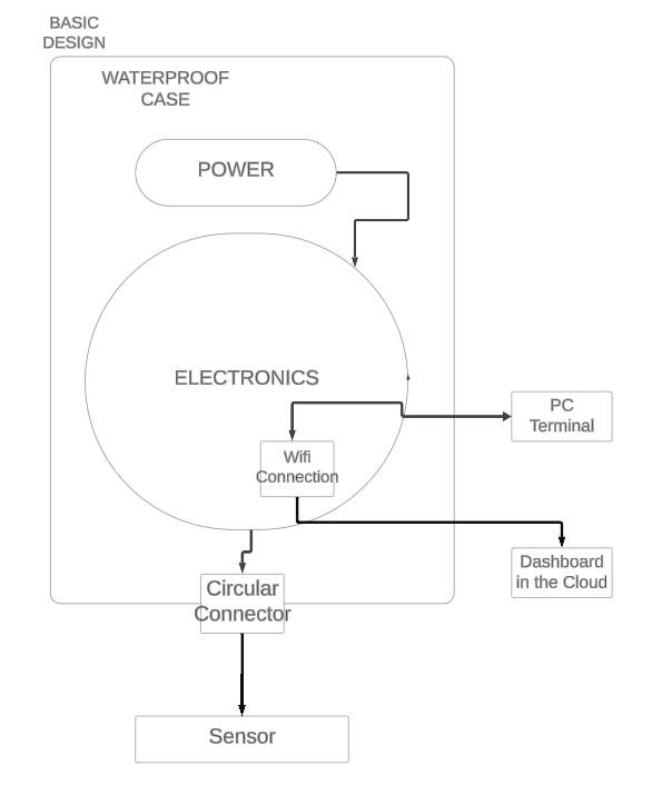
Basic Design Diagram
This diagram shows the functionality in a basic design diagram. This diagram visually depicts the functional components and their relationships.

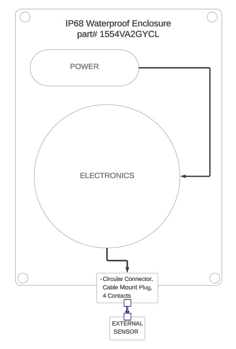
ENCLOSURE Functional Diagram
The following Diagram describes the Enclosure that was supplied for the Challenge the parts are:
- IP68 waterproof Enclosure part# 1554VA2GYCL
- 3 piece connector Attached to the Enclosure through a pre-drilled hole
- Circular Connector, Cable Mount Receptacle, 4 Contacts
- Circular Connector, Cable Mount Plug, 4 Contacts
- Circular Connector, Panel Mount Receptacle, 4 Contacts
The enclosure is the housing for the electronics. It is an IP6-rated enclosure, which means that it is protected from dust and water.
Enclosure Design Diagram

Technical Design
Electronic Design
- The electronics that will be placed into the enclosure to test the IP6 ratings of the enclosure consist of several key components. At the heart of the system is a microcontroller unit (MCU), which serves as the brains of the operation The MCU is responsible for controlling the various sensors and actuators within the enclosure, as well as communicating with external devices.
- The enclosure also includes a number of sensors to monitor the environmental conditions inside the enclosure. These sensors include temperature, humidity, and pressure sensors. The data collected by these sensors is used by the MCU to ensure that the enclosure is operating within the specified IP6 rating.
- The electronics are powered by a Power Supply. The Power Supply provides the electrical power needed to operate the MCU, sensors, and actuators.
- The electronics are all enclosed in a weatherproof housing. The housing protects the electronics from the elements and ensures that they are operating in a safe and reliable environment.
- The electronics are an essential part of the IP6 testing process. They provide the necessary control and monitoring to ensure that the enclosure is operating within the specified IP6 rating.
Electronic Components
The electronics that make up the electronics that will be placed into the enclosure to test the IP6 ratings of the enclosure are as follows:
- Power supply: The power supply provides the necessary power to the electronics. This could be a Battery, DC Power,or a USB Device Charger.
- Microcontroller: The microcontroller is the brain of the electronics. It controls all of the functions of the electronics. It is an Pi4 Compute Module I/O Board with a Pi4 Compute Module attached.
- Sensor(s): The sensors are used to measure the environmental conditions inside the enclosure. They include a temperature sensor, a humidity sensor, and a pressure sensor.
- A Pimoroni Enviro - Indoor Monitor Pi Hat is used to attach to the Pi Hat connector on the I/O board
- Display: Data is displayed on an Alphanumeric, 20X4 screen
- Antenna: Antenna is attached to the Pi4 I/O board and it is used to communicate with the outside world.WiFi is used to send data to Dashboard in the cloud. The data includes the temperature, humidity, and pressure readings from the sensors.
- PC Terminal: Used to access the board over Wi-Fi using Putty.
- Dashboard in the Cloud: Date is sent to the cloud for visualization.
The Pi4 Compute Module is powered up when the power supply provides electricity. The power supply can be an AC adapter or a battery. Once the Pi4 Compute Module has power, it initializes all of the sensors connected to it. This process involves setting up the communication protocols and configuring the sensors so that they can provide accurate data.
After the sensors have been initialized, the microcontroller begins reading the sensors to gather environmental conditions inside the enclosure. The microcontroller is the brain of the system and is responsible for controlling all of the functions of the enclosure. The microcontroller relies on sensor data to report environmental conditions both inside and outside the enclosure. Additionally, it evaluates whether these internal conditions align with the desired range. If discrepancies arise, the microcontroller intervenes by implementing corrective measures. These measures may include activating a fan for cooling purposes or opening a vent to facilitate fresh air circulation.
Flow Diagram
The diagram presented below, illustrates the electronic components to be placed in the enclosure for IP6 Ratings testing. It visually represents the functional components of the electronics and their interconnections. Using a simplified class diagram, it showcases the software associated with each component.
The diagram provides a graphical representation of the functional components in an electronics system and their interconnections. It utilizes the fundamental principles of a Class diagram, commonly used in software engineering, to illustrate the software associated with each component. This diagram is a valuable tool for understanding the architecture and functionality of an electronic system.
Each component in the diagram is represented by a rectangle, and its name is displayed inside the rectangle. The relationships between components are depicted using lines connecting the rectangles. These lines can represent different types of relationships, such as data flow, control flow, or physical connections.
The diagram also includes information about the software associated with each component. This information is typically displayed within the rectangle representing the component. It can include details such as the software's name, version, and functionality.
By combining the visual representation of components with information about the associated software, the diagram provides a comprehensive overview of the electronics system. It enables stakeholders to understand the system's architecture, identify potential integration points, and troubleshoot issues.
Additionally, the diagram can serve as a valuable documentation tool. It can be used to communicate the design and functionality of the system to technical and non-technical stakeholders. It can also be used as a reference during development, testing, and maintenance activities.
NEXT
Blog#2 Deep Dive into the Electronic IoT Parts
This blog will include a deep dive into the electronic parts supplied by Hammond for the challenge
