


Hello everyone. I welcome you to my next blog as part of Experimenting with Supercapacitors. In previous two blogs I described my experimental large capacitance measurement using python and now I switch to something different. In this blog I will describe my circuit used for evaluation real energy density of the supercapacitors which allows me to answer some questions mentioned in my first blog like “Does 1F capacitor rated to 5.5V allows storing 4x more energy than 2.7V while it is about 4x more expensive?”.
Test
To test real energy density, I will run a following test. I will charge supercapacitors and then load capacitor by LED. I will measure how long it will take until the LED turn off.
Capacitance vs Power Density
Most people naturally think that the amount of energy stored in the capacitor depends on capacitance. It is definitely true, but there is another factor: voltage. If you charge capacitor to 3V and then load (for example, by LED), it will light less time then you charge the same capacitor to the 6V. From practical point of view, if the energy stored in the capacitor is important, it is good idea to charge capacitor to voltage as high as possible. In other words: charge it to the rated voltage.
In supercapacitors kit we have capacitors with rated voltages 2.7V, 3.0V, 3.6V, 3.8V and 5.5V. Even better, for demonstrating impact of rated voltage we have two capacitors with the same capacitance (1F), but different rated voltage (2.7V and 5.5V).
One my initially think, that doubling the rated voltage will double the time the LED will lit, but this is not true. For better understanding I recommend imaging the boost converter. The boost converter convert lower input voltage (for example, voltage form the supercapacitor) to the higher constant output voltage (for example, for powering LED). While input voltage is lower, for maintaining load demands input current must be higher than output current. Otherwise, it would be perpetuum mobile because it outputs more energy than it sources. In practise output and input energy expressed as P = U * I will be almost equal, but there are some loses, so the input will be slightly higher, but for simplicity, it will be very similar. Now, lets back to the capacitor. When the capacitor gets charged to the higher voltage than the other one, the current coming from capacitor to the boost regulator will be lower. Lowering the current results to the behaviour that the capacitor discharges slower. And now if we go back to doubling rated voltage example, we can realize that time the LED will lit is much longer, because at the region of additional voltage, the capacitor will discharge slower, than in the lower part when it discharges exactly as in the case of the capacitor with half the rated voltage.
Schematics
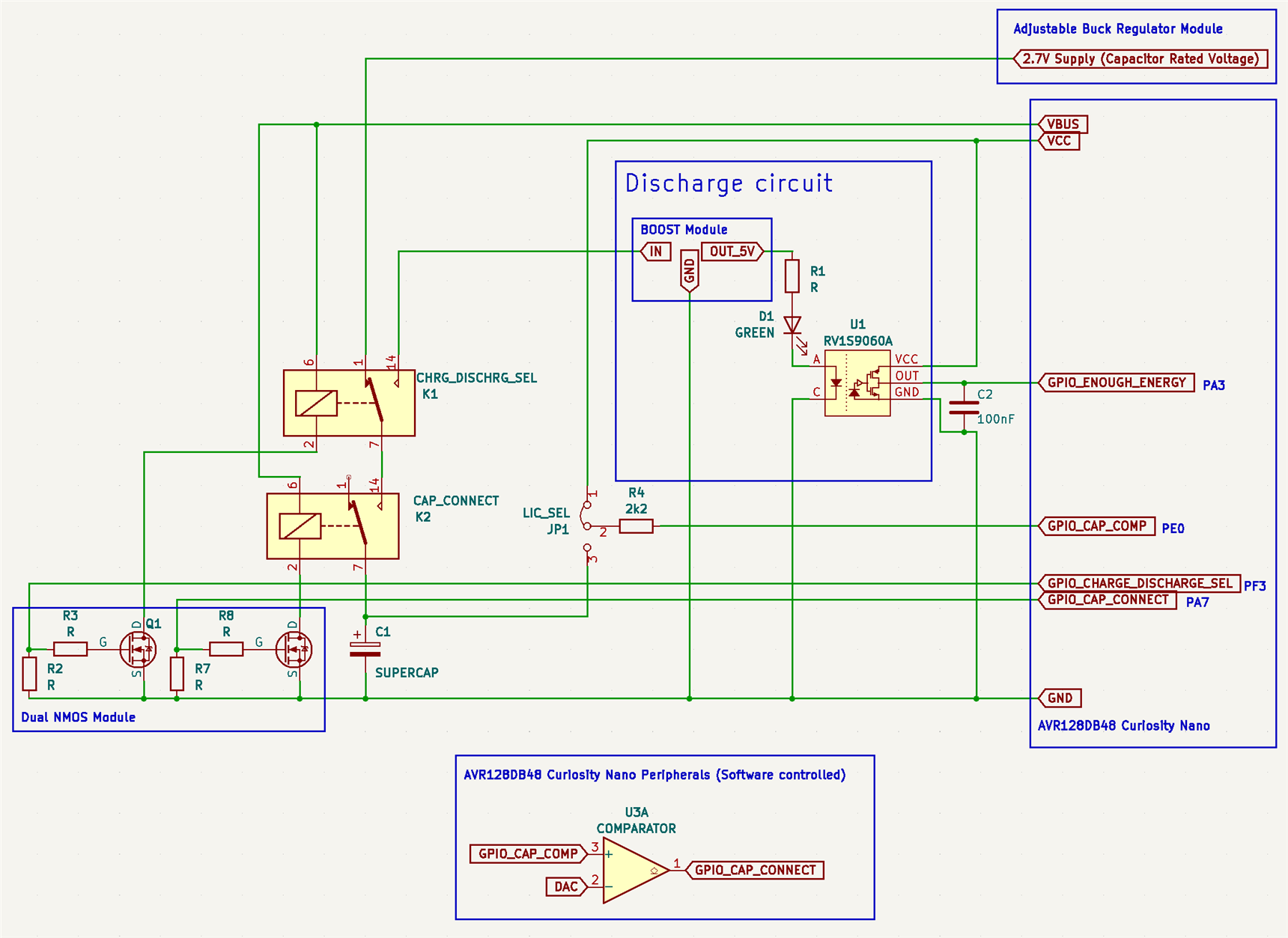
Now lets’ look the to the schematics of the testing circuit.
Testing Circuit Description
Testing circuit is driven by microcontroller this time. I originally planed do it with Raspberry Pi like I did in previous experiment, but all my Pis are used by other experiments, so this time I did it with microcontroller. Additionally, I used comparator inside the microcontroller. As a microcontroller I used AVR128DB48 on the Curiosity Nano board for its capability of adjusting VCC voltage from Atmel Studio, capability of running at 5V and ease of development. Like in previous experiment there are relays for switching paths. There are two relays this time. The upper relays is used for selecting charging or discharging path to the supercapacitor. MCU can switch them by GPIO pin (PF3). The charging path is connected to the external buck DC/DC regulator which is set slightly below the rated voltage of the capacitor (I set it about 50mV below). For every measured capacitor this regulator needs to be adjusted. The discharge path is connected to the boost regulator. I was thinking about using it directly connected, but the boost regulator is more realistic case. While nowadays digital electronic can support wide range of power supply, most supercap powered system (like my temperature sensor described in first blog) still uses boost regulator which generates fixed constant voltage. For this reason, I used boost regulator here also. It generates 5V no matter of the actual voltage of capacitor. Theoretically it can run down to 0.4V on input but this has some limitations which I will describe later. Boost convertor powers LED as a load. I originally planned to use digital light sensor connected to the microcontroller for detecting time when the LED turn off, but later I realized that there is the device which has internal LED and digital indication that LED is turn OFF or ON on the other side – it is a optocoupler. So practically I connected two LEDs in series. One green for indication and there is second LED in the optocoupler. After it turn off, transistor inside the optocoupler switches and MCU can easily detect it. LED resistor (R1) is adjusted to pass 4.22mA discharge current flowing through both LEDs. The second relay is used for connecting and disconnecting capacitor from both charger and discharger. Generally, it is not needed for general purpose supercapacitors (EDLCs) but there is need to prevent undercharging lithium-ion supercapacitors (LICs). For implementing this protection, I use comparator. I use comparator integrated in the microcontroller. For setting negative input of comparator, I use internal DAC in the MCU which uses another internal voltage reference. The output from this comparator drives the second relay in the discharge phase. The undercharging protection disconnect circuit from capacitor immediately after it discharge until voltage level configured by firmware. But such disconnection do not need any further SW intervention. For enabling or disabling this protection there is jumper (JP1) which in case of standard EDLC supercapacitors brings the microcontroller power voltage which remains comparator voltage above the configured threshold for all time and allows fully discharge the capacitor. It efficiently disables the over discharging protection. Additionally, I added RGB led for indications (it is not visualized on the schematics).
Realization
The circuit I connected on the breadboard.

For practical tests I charged capacitors for 10 minutes to about rated voltage minus 50mV and large capacitance lithium-ion capacitors I charged for 15 minutes. As mentioned, this time they were charged by constant voltage power source without any explicit current limitation.
Firmware
After power-up firmware initialize HW and move to ready state indicating by green color status RGB LED. After pressing onboard button, it switches relays to charge capacitor. This is indicating by yellow color status RGB LED. After 10- or 15-minutes elapse, it switches the path to discharge path and enables over discharge protection. It starts timer in capture mode. Timer capture happens when the input pin driven by the transistor in the optocoupler switches which indicates that the LED inside the optocoupler turned off and capacitor were “fully” discharged. Actually, practical evaluation shown that it is not fully discharged because when the voltage drops low, the current demand on the input side increase which cause additional voltage drop due to capacitor ESR. Due to such voltage drop boost regulator terminates sooner (at about 0.8V) but for practical evaluation it does not matter because the same pattern happens in real circuit, and I want to do my experiment under realistic conditions. In fact, after it shutdown and current demand drops, the voltage on the capacitor grows back again, which cause interesting behaviour, that circuit starts regulator again, but immediately fail and this pattern repeat for some time. My circuit measure time to the first power failure. Discharging phase is indicated by flashing blue status RGB LED. After circuit lose reliable power for a first time, firmware evaluates if the failure was triggered by discharge of capacitor or by disconnecting circuit by undercharging protection. Situations are distinguished by status RGB which can after completing measurement show cyan or purple color depending on the end type (it can also show red color if the time is too long and counter overflown). You can see it in the action on the following video. For test purpose I reduced charging time to 5 seconds which is enough to charge connected capacitor, but not to reduce it’s self-discharge current. Outputs are printed over UART.
Results
This circuit I used against all supercapacitors in the kit. Here are the times converted from the timer output to the real time (firmware prints measured time in the raw timer tick count).
|
Capacitor |
Rated V |
Charged to V |
Time to power fail |
|
DGH 1F |
2,7 |
2,644 |
00:02:27 |
|
DGH 5F |
2,7 |
2,644 |
00:13:04 |
|
DGH 10F |
2,7 |
2,644 |
00:24:54 |
|
DSF 3F |
3,0 |
2,949 |
00:09:12 |
|
DSF 7F |
3,0 |
2,952 |
00:21:55 |
|
DSF 25F |
3,0 |
2,936 |
01:14:24 |
|
EDS 0.1F |
5,5 |
5,446 |
00:00:33 |
|
EDS 0.22F |
3,6 |
3,554 |
00:00:33 |
|
EDC 0.47F |
5,5 |
5,446 |
00:02:31 |
|
EDC 1F |
5,5 |
5,446 |
00:09:26 |
|
VMF 25F |
3,8 |
3,739 |
01:01:22 |
|
VMF 40F |
3,8 |
3,746 |
01:53:41 |
|
VPF 40F |
3,8 |
3,742 |
01:42:52 |
I plan to publish very detailed analysis of these results in my final blog. For now, let’s look at basics. At first, we can see that within the same family time grows almost linearly depending on capacitance. For example, DGH 5F unit should power circuit five times longer than 1F and it actually does (5,33×). Similarly, 10F unit should be twice more (actually it is 1,9×) and 10 times more than 1F unit (actually it is 10,16×). Now let’s look at the 1F units having the same capacitance but differing in rated voltage. From the table above:
|
Capacitor |
Rated V |
Charged to V |
Time to power fail |
|
DGH 1F |
2,7 |
2,644 |
00:02:27 |
|
EDC 1F |
5,5 |
5,446 |
00:09:26 |
EDC unit is about 4x more expensive. And really, it powered circuit much longer (3,85×) which confirms the theory. Additionally, 0.1 and 0.22F units from EDS family are also interesting. In one of the previous article, I mentioned that the higher capacitance unit has lower rated voltage, so the real energy density will most probably will be very similar. And it actually is:
|
Capacitor |
Rated V |
Charged to V |
Time to power fail |
|
EDS 0.1F |
5,5 |
5,446 |
00:00:33 |
|
EDS 0.22F |
3,6 |
3,554 |
00:00:33 |
Actual difference based on precise timer measurement is 0,549 seconds. Both remain charged for very similar time about 33 seconds. So, as you can see twice the capacitance is not always better. Also note that higher capacitance but lower rated voltage unit is about half the physical size, so for space constrained application it looks better. The other unit may work better for applications without boost converter with large working voltage range.

The longest run was of course with the highest capacity lithium-ion supercapacitors from VMF and VPF family.
Conclusion
This is all for this blog post. In this blog I described my circuit for experimentally measuring real energy density of supercapacitors and shown my results from measurements. As mentioned, in final blog I will publish more detailed analysis. Time is running out very quickly. I received all things needed to complete all experiments. Currently I measure self-discharge of the capacitors and also in parallel I measure capacitor connected to my Mini Solar Powered Wireless Temperature Sensor. I hope you liked this blog post and I welcome any feedback in the comments below. Thank you for reading it. Enjoy rest of the day.
Next blog: Measuring Self Discharge
