element14 Community
element14 Community
    Register Log In
  • Site
  • Search
  • Log In Register
  • About Us
  • Community Hub
    Community Hub
    • What's New on element14
    • Feedback and Support
    • Benefits of Membership
    • Personal Blogs
    • Members Area
    • Achievement Levels
  • Learn
    Learn
    • Ask an Expert
    • eBooks
    • element14 presents
    • Learning Center
    • Tech Spotlight
    • STEM Academy
    • Webinars, Training and Events
    • Learning Groups
  • Technologies
    Technologies
    • 3D Printing
    • FPGA
    • Industrial Automation
    • Internet of Things
    • Power & Energy
    • Sensors
    • Technology Groups
  • Challenges & Projects
    Challenges & Projects
    • Design Challenges
    • element14 presents Projects
    • Project14
    • Arduino Projects
    • Raspberry Pi Projects
    • Project Groups
  • Products
    Products
    • Arduino
    • Avnet Boards Community
    • Dev Tools
    • Manufacturers
    • Multicomp Pro
    • Product Groups
    • Raspberry Pi
    • RoadTests & Reviews
  • Store
    Store
    • Visit Your Store
    • Choose another store...
      • Europe
      •  Austria (German)
      •  Belgium (Dutch, French)
      •  Bulgaria (Bulgarian)
      •  Czech Republic (Czech)
      •  Denmark (Danish)
      •  Estonia (Estonian)
      •  Finland (Finnish)
      •  France (French)
      •  Germany (German)
      •  Hungary (Hungarian)
      •  Ireland
      •  Israel
      •  Italy (Italian)
      •  Latvia (Latvian)
      •  
      •  Lithuania (Lithuanian)
      •  Netherlands (Dutch)
      •  Norway (Norwegian)
      •  Poland (Polish)
      •  Portugal (Portuguese)
      •  Romania (Romanian)
      •  Russia (Russian)
      •  Slovakia (Slovak)
      •  Slovenia (Slovenian)
      •  Spain (Spanish)
      •  Sweden (Swedish)
      •  Switzerland(German, French)
      •  Turkey (Turkish)
      •  United Kingdom
      • Asia Pacific
      •  Australia
      •  China
      •  Hong Kong
      •  India
      •  Korea (Korean)
      •  Malaysia
      •  New Zealand
      •  Philippines
      •  Singapore
      •  Taiwan
      •  Thailand (Thai)
      • Americas
      •  Brazil (Portuguese)
      •  Canada
      •  Mexico (Spanish)
      •  United States
      Can't find the country/region you're looking for? Visit our export site or find a local distributor.
  • Translate
  • Profile
  • Settings
Experimenting with Thermal Switches
  • Challenges & Projects
  • Design Challenges
  • Experimenting with Thermal Switches
  • More
  • Cancel
Experimenting with Thermal Switches
Challenge Blog Blog #1: LED Life Booster/Extender
  • Challenge Blog
  • Forum
  • Documents
  • Files
  • RoadTests
  • Mentions
  • Sub-Groups
  • Tags
  • More
  • Cancel
  • New
  • Share
  • More
  • Cancel
Group Actions
  • Group RSS
  • More
  • Cancel
Engagement
  • Author Author: karthikrajagopal
  • Date Created: 30 Jan 2022 11:28 AM Date Created
  • Views 2810 views
  • Likes 10 likes
  • Comments 5 comments
  • thermal switch
  • kemet
  • reed switches
  • experimenting with Thermal Switches
Related
Recommended

Blog #1: LED Life Booster/Extender

karthikrajagopal
karthikrajagopal
30 Jan 2022

Self-Intro:

I am Karthik Rajagopal, pursuing my UG course on Electronic Engineering. I am currently working as a Hardware Engineer in a Start-up company as a part of my Internship. I have come across a lot of designs and design constraints  in electronics which has led me to learn further and expand my knowledge in Circuit designing.  Keeping up with the present-day technology is one of the key aspects that has helped me progress.

My experience with Thermal Switches:

Though my field of work does not involve much of power electronics, I have found many situations which needed the application of Thermistors and Thermal switches. One such application I have worked with is a battery  charger. The popular use of Thermistors for soft starting was needed in that circuit. Another application was to have 3 stages of controlled heating in a water heater which was accomplished by  Thermal Switches. Since they have a fixed cut off temperature and can directly be wired up to mains voltage, the whole design cost drastically reduced. A simple network of 5 to 6 thermal switches were used to create heating stages with two thresholds.

                                   image

Problem in current technology:

I recently came across a post about the evolution of LED technology from just being an indicator light to the wide spectrum of applications  it is currently used in. Among those, using them as lighting solution has a good impact on our environment compared to the conventional CFL and Tungsten based  lighting.

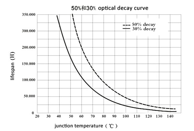
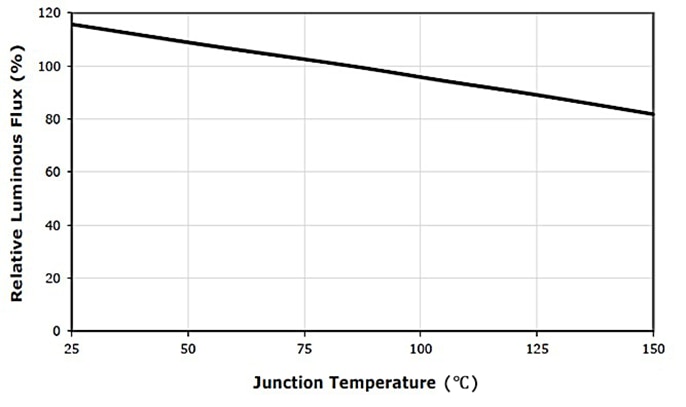
While having a better luminous flux to current ratio, the life of those LEDs is limited by a few factors. One such factor is heat. With time, the heat in the LED lamps we use reach a temperature which when operated in the same condition affects the life of the LED bulb.

image

image

Source: https://www.agcled.com/blog/the-application-of-outdoor-led-lights-in-cold-places.html

My Solution and Test Procedure:

My solution to the above problem is to switch between two sets of lighting panel inside the same unit based on heat. This will ensure a better LED life while also maintaining the brightness after switching. The switching will be done by the Thermal switches provided by KEMET.

The threshold temperature will be identified and an appropriate switch will be attached to the heat sink of the LED panels.

image

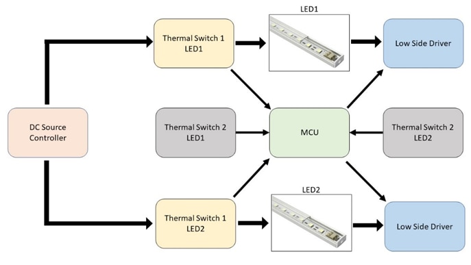
The circuit will be utilizing a pair of Thermal Switches for each LED strip. This is done to ensure a smooth transition from LED1 to LED2 after reaching the threshold.

The Microcontroller (An Arduino in my case) will take care of the timing aspects in switching.
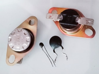
 

KEMET Switches:

image

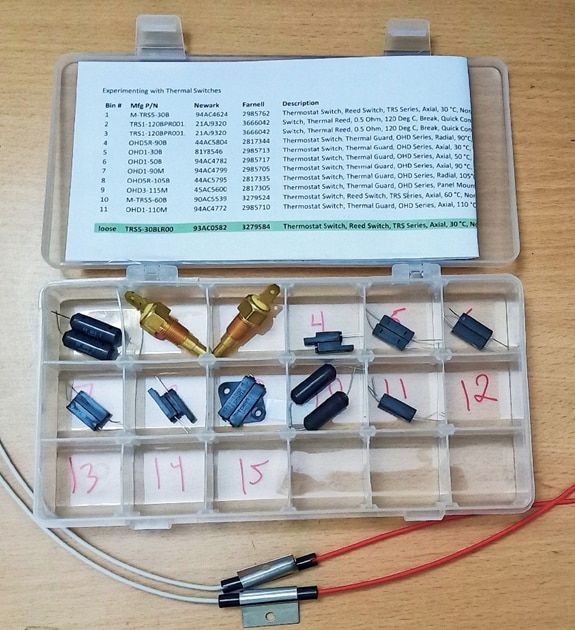
The kit of 11 Thermal Switches was very well packed and labelled. I will be testing out the thermal switches with Curie temperature from  30°C to 90°C. Based on hysteresis of the switches, the cut off temperature and timing will be decided.

                                                                                                                                        Blog #2>

  • Sign in to reply

Top Comments

  • Gough Lui
    Gough Lui over 3 years ago +1
    That seems like an interesting proposal, however, I'm not sure that this is the best idea. One reason is that simply turning the second panel on while turning the first panel off is going to result in…
  • karthikrajagopal
    karthikrajagopal over 3 years ago in reply to robogary

    Thanks for the feedback

    Yes, the LEDs are PWM controlled and for the switching loss, I have ignored it as the loss is not that significant. 

    • Cancel
    • Vote Up 0 Vote Down
    • Sign in to reply
    • More
    • Cancel
  • karthikrajagopal
    karthikrajagopal over 3 years ago in reply to Gough Lui

    The thermal aspect was where I was stuck while drafting my proposal. I then decided to use MCU to reduce the brightness by using a PWM signal as this  allows to control the current consumed by the LED strip. This way, I thought of gradually reducing the brightness of LED1 while increasing the brightness of LED2 to have a more gradual temperature and brightness change. 

    I most probably will have to do minor changes in the circuit as switching between panels will be tougher than expected at least after seeing the sensitivity of these switches to atmospheric temperature. Heat transfer between these adjacent strips can easily mess up with the sensing.

    Thanks for highlighting the delamination issue of lens and gold wires,I was not aware of that.

    • Cancel
    • Vote Up 0 Vote Down
    • Sign in to reply
    • More
    • Cancel
  • robogary
    robogary over 3 years ago

    Hi Karthik - Interesting idea.

    I suspect the LED bulbs are PWM controlled and not straight flat DC and have switching loss content.

    I am not an LED light bulb expert, but I could even imagine light bulbs being designed for 100W, and the 30W bulbs are exact same construction, just with the internal switching power supply phased back to a lower voltage. 

    If I could be so bold as to suggest  some additions to your idea, one is to add junction temperature calculations if possible,

    Another idea for your study is to see the impact of a dimmer switch on the LED bulb. Dimmers on incandescent bulbs are a no brainer as they put out alot of heat, and reducing voltage reduced the heat directly by reducing watts loss.    

    I dont know if LED bulbs would be hotter if dimmed, stay the same , or run cooler.  There is a tradeoff there of I2R losses in heat for switching losses.  

    • Cancel
    • Vote Up 0 Vote Down
    • Sign in to reply
    • More
    • Cancel
  • Gough Lui
    Gough Lui over 3 years ago

    That seems like an interesting proposal, however, I'm not sure that this is the best idea.

    One reason is that simply turning the second panel on while turning the first panel off is going to result in the panels being cycled. The thermal cycling causes expansion and contraction stresses on the panel PCB and LED packages which can cause failure by delamination of lenses or gold bond wires over time. As each panel is operating at the full drive current (presumably) while it is on, it is likely that the second panel will then come up to temperature and you may switch back to the first but it has not cooled down all that much which could lead to endless cycling?

    Maybe it is best (from my experience) to run both LED panels in parallel (as you already have twice the LEDs you need) with the same drive current spread across the two. With now halved drive current and double dissipation area, the temperature will be much lower and you will actually gain an increase in light output as the LEDs running at lower currents usually are more efficient as they suffer less from internal resistive losses. If you are targeting the same brightness, then you can reduce the current slightly because of the increased operating efficiency.

    Most LED torches, for example, use a thermistor or other "continuous" reading temperature sensor to adjust the drive current to target a particular maximum heatsink temperature to avoid overheating. As the thermal switches provide a discrete output, perhaps you can reduce the drive current based on reaching a temperature threshold, rather than switching between panels, as that may be more effective in protecting the LEDs but this will have an obvious effect on the output.

    - Gough

    • Cancel
    • Vote Up +1 Vote Down
    • Sign in to reply
    • More
    • Cancel
  • navadeepganeshu
    navadeepganeshu over 3 years ago

    Great plan karthikrajagopal! LED parts are tortured very much by their own heat....

    • Cancel
    • Vote Up 0 Vote Down
    • Sign in to reply
    • More
    • Cancel
element14 Community

element14 is the first online community specifically for engineers. Connect with your peers and get expert answers to your questions.

  • Members
  • Learn
  • Technologies
  • Challenges & Projects
  • Products
  • Store
  • About Us
  • Feedback & Support
  • FAQs
  • Terms of Use
  • Privacy Policy
  • Legal and Copyright Notices
  • Sitemap
  • Cookies

An Avnet Company © 2025 Premier Farnell Limited. All Rights Reserved.

Premier Farnell Ltd, registered in England and Wales (no 00876412), registered office: Farnell House, Forge Lane, Leeds LS12 2NE.

ICP 备案号 10220084.

Follow element14

  • X
  • Facebook
  • linkedin
  • YouTube