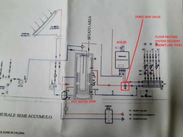
- a low temperature sensor: when water from solar panel is too cold (below 30 °C), there is no need to send water to the heating system. The three-way valve stays close

- a high temperature sensor: when water from solar panel is too hot (above 50 °C), the control system will open and close the mixer valve in a timely manner. In this way, the thermal capacitance of the house floor will dampen the thermal peaks
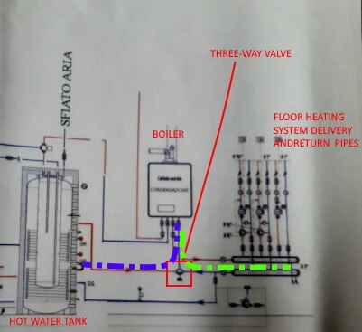

The NE555 is going to be connected in an astable configuration and, when switched on, generates a waveform with a time on of roughly 15 seconds with two different periods:
- when the OHD1-50B sensor is closed (temperature from solar water tank below 50°C), the period is 30 seconds
- when the OHD1-50B sensor is open (temperature from solar water tank above 50°C), the period is 120 seconds
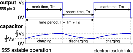
The NE555 in a typical astable configuration is shown in picture below
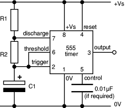
Here is a brief description of astable operation.
- With the output high (+Vs), the capacitor C1 is charged by current flowing through R1 and R2
- The threshold and trigger inputs monitor the capacitor voltage and when it reaches 2/3Vs (threshold voltage), the output becomes low and the discharge pin is connected to 0V
- The capacitor now discharges with current flowing through R2 into the discharge pin
- When the voltage falls to 1/3Vs (trigger voltage) the output becomes high again and the discharge pin is disconnected, allowing the capacitor to start charging again
This cycle repeats continuously unless the reset input is connected to 0V which forces the output low while reset is 0V. Because we want to achieve a duty cycle of less than 50%, we need a diode in parallel with R2. This bypasses R2 during the charging part of the cycle so that Tm depends only on R1 and C1:
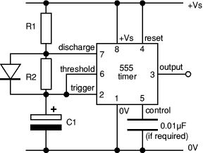
This leads to the following formulas
Tm = 0.7 x R1 x C1
T = Tm + Ts = 0.7 x (R1 + R2) x C1
where T is the waveform period and Tm is the time the signal is high (mark time)
To achieve different periods, the OHD1-50B sensor and a resistor (R22) are connected in parallel to R2 as shown in this circuit diagram
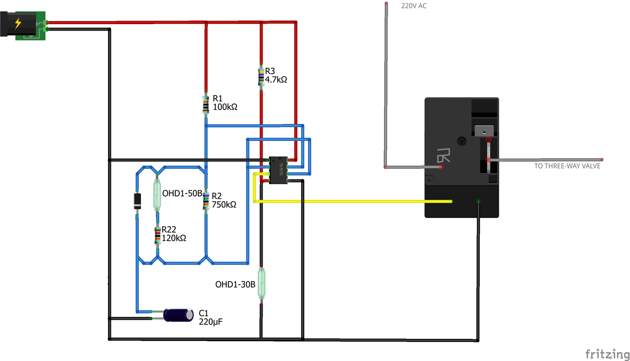
When water temperature is below 50 °C, OHD1-50B is closed and the period is
T = Tm + Ts = 0.7 x (R1 + (R2 || R22)) x C1
where (R2 || R22) is the resistor equivalent to R2 in parallel with R22. When water temperature is above 50 °C, OHD1-50B opens and the period is
T = Tm + Ts = 0.7 x (R1 + R2) x C1
Let's first select C1 to be 220 uF. Let's first calculate R1 and R2 when sensor OHD1-50B is open (temperature above 50 °C) Assuming R1=100K the time on (Tm) is
Tm = 15 seconds
From the formulas, we can now derive the value of R2
R2 = 750K
With these values, the period is 131 seconds. When R1 and R2 when sensor OHD1-50B is closed (temperature below 50 °C), since values of R1 and C1 are now fixed and the desired period is about 30 seconds, we can impose R2 || R22=100K which leads to R22 = 120K With these values of R1, R2, R22 and C1 the period is 31 seconds. Time on (Tm) does not change because it depends only on values of R1 and C1 The output of NE555 will directly drive a relay coil, that in turns will open and close the three-way valve.
Note that, when water temperature is below 30 °C, the 555 is kept in reset state by the OHD1-30B
Here is a demo video that shows the control circuit at work. Resistors have been changed to reduce on/off period to limit the duration of the video

-

dansmith57
-
Cancel
-
Vote Up
0
Vote Down
-
-
Sign in to reply
-
More
-
Cancel
-

amgalbu
in reply to dansmith57
-
Cancel
-
Vote Up
0
Vote Down
-
-
Sign in to reply
-
More
-
Cancel
Comment-

amgalbu
in reply to dansmith57
-
Cancel
-
Vote Up
0
Vote Down
-
-
Sign in to reply
-
More
-
Cancel
Children