


Let's measure some temperatures using Molex thermistors! But, where shall we begin?
A thermistor is basically a resistive element whose electrical resistance changes when it is subjected to heat. So, if we can sense this change in resistance, we can map it to the actual temperature accordingly. The easiest way to do it is perhaps using a potential/voltage divider as shown in sketch below.
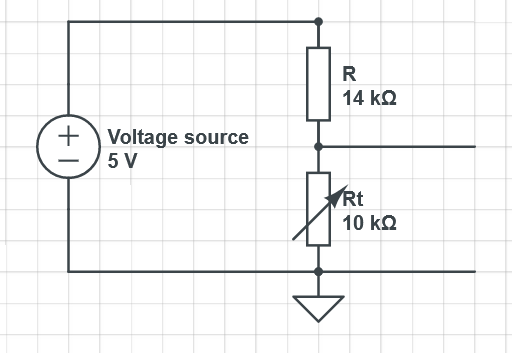
Here, 5V is supplied to the resistors in series, R and Rt, and voltage is measured across Rt. Since, the resistors R + Rt are in series, the voltage acros R and Rt will be proportional to the ratio they both make. In the figure above, voltage across Rt will be 5V * Rt/(R+Rt) = 2.083V and across R will be 5V * R/(R+Rt) = 2.917V. Now, suppose the temperature increases to a certain value which makes the thermistor resistance to go down to about 8kOhm. In that case, the voltage across it will be seen as 5V * 8/(14+8) = 1.818V. Therefore, the change in voltage can be measured directly. If we know the relationship between change in voltage that corresponds to the change in temperature, we can calculate the temperature value by measuring this voltage drop. If the relationship is not known, we can measure the temperature using a trusted device and record voltage drop to obtain the relationship - this is known as calibration. Fortunately, in our case, the relationship is known - Steinhart-Hart equation - and thanks to Molex that we know the necessary parameters, too! So, we can simply measure the voltage, work out the thermistor resistance and then convert it to temperature using that equation.
Temperature measurement
I chose Arduino Nano 33 IoT for the data acquisition (essentially voltage measurement) for several reasons:
- It has WiFi module which helps be getting the data from room bound computers or laptop/raspberry pi without wired connection to the measurement board.
- It can do 16-bit resolution with oversampling.
- It has 8 analog input channels (although only 6 shall be used as inputs per the recommendation in their datasheet)
However, using Nano meant that I can input maximum of only 3.2V because its I/Os are not tolerant to 5V. This means that I have to choose the resistanct R such that the voltage across Rt does not exceed 3.2V. For this, I considered the temperature at which the resistance will be at its higher range, i.e. lower range of the temperature. This is because the thermistors are NTC, meaning Negative Temperature Coefficient and the resistance will increase with decreasing temperature. So, 5V being divided across constant (R) and variable resistor (Rt), voltage drop across Rt increases when Rt increases. Keeping this in mind and the expected lowest value of the temperature, I used the Steinhart-Hart model to work out what resistance value would a thermistor reach. Steinhart-Hart equation is
1T=1T0+1betalnRR0.
which when rearranged, gives Rt as shown below.
Rt=R0×e(beta·(1T−1T0)).
Here, beta is the coefficient of the non-linear part of the equation, R0 is the electrical resistance of the thermistor at temperature T0 (25 degree C in this case), Rt is the electrical resistance of the thermistor at temperature T.
Using the parameters given by Molex, I calculated the max reistance that may be attained at the expected temperature for the thermistors I have used. These are tabulated below. The final value of the fixed resistors varied sightly - due to the availability of nearest value resistor.
| Thermistor | R0 (kOhm) | Lowest considered temperature (degree C) | Rt at lowest considered temperature (kOhm) | R (kOhm) fixed [3.2/5 * Rt at lowest temperature] | R (kOhm) that is used |
| Thermistor1-Heater | 10 | -10 | 47.65 | 28.5 | 27.15 |
| Thermistor2-Ceiling | 4.7 | 0 | 16 | 9.6 | 9.11 |
| Thermistor3-Curtain | 10 | 10 | 19.65 | 11.79 | 12.08 |
| Thermistor4-Window | 12 | 10 | 23.58 | 14 | 14.98 |
To help me reduce the work load of calculating all Rt values by hand, I wrote a little python script as shown below. Simply run this from your IDE or locate the directory where you save this python script and execute it from terminal.
# Calculate resistance of thermistor at a temperature
# Author: Hitesh Boghani
# Date: 11-Sept-2022

import math

def getThermistorResistance(beta,R0,T):

	T0 = 25
	K = 273.15
	R = R0 * math.exp(((1/(T+K))-(1/(T0+K))) * beta)

	return R

cmd = 'y'

while cmd == 'y':
	print('Enter beta value of the thermistor: ')
	beta = float(input())
	print('Enter resistance value of the thermistor at T = 25 degC: ')
	R = float(input())
	print('Enter temperature at which you need thermistor value: ')
	T = float(input())

	R = getThermistorResistance(beta,R,T)

	print('Resistance of your thermistor at temperature ', T, ' degC will be ', R, 'Ohm')

	print('Do you want to restart the program?(y/n)')

	cmd = input()


print('Program ended!')
I followed the article that I bumped into, after finding it in someone's blog, perhaps referenced by ntewinkel - which mentions self-heating. To avoid that, I used a transistor to switch the 5V on only whilst measuring the temperature. So the measurement circuit looks like this.
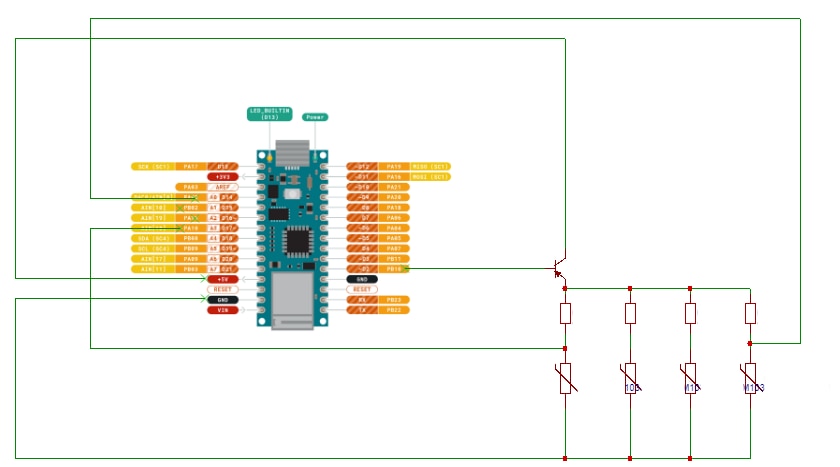
For sanity, I have not connected some thermistors in the schematic. The corresponding real-life circuit on a breadboard looks like this. Thermistors are numbered from thermistor1 from arduino side towards the tea - last one being thermistor4.

You might be wondering  what is the role of tea here? I will reveal it down below but you may have guessed it already!
For the power, I got a battery pack and a booster to provide 5V to arduino so that a long USB/power cable can be avoided making it safer to operate without trip hazards around my room!
Recording the data
Arduino Nano 33 IoT has wireless connectivity which makes it possible to do data transfer using the internet. In particular, I considered using UDP because it doesn't care about handshake etc (unlike TCP) and you can get the data as long as there is correct IP and port info and command. So, I used the arduino as a server which sends the measured data upon request and a Raspberry Pi as a client which asks for the data and stores the response in a text file.
A complete code that goes in arduino is shown below.
/*
 * Experimenting thermistors challenge - element14 community
 * Project: Profiling heat in a room
 * Author: Hitesh Boghani
 *
*/

#include <SPI.h>
#include <WiFiNINA.h>
#include <WiFiUdp.h>

#include "arduino_secrets.h"

#define ADC_RES 16
#define NO_OF_THERMISTORS 4
#define THERMISTOR_PWR 2

char ssid[] = SECRET_SSID;      // Wifi SSID
char pass[] = SECRET_PASS;       // Wifi password
int keyIndex = 0;                // Network key Index number (needed only for WEP)
int status = WL_IDLE_STATUS;

unsigned int localPort = 3232;  // Local port to listen on

char packetBuffer[256]; // Buffer to hold incoming packet
char replyBuffer[1024];  // a string to send back
String dataBuffer;
unsigned long timeStamp; // to store timestamp

float volts[NO_OF_THERMISTORS];
float temperature[NO_OF_THERMISTORS];
float beta[NO_OF_THERMISTORS] = {3500,3802,3802,3802};
float R0[NO_OF_THERMISTORS] = {10000,4700,10000,12000};
float R[NO_OF_THERMISTORS] = {27150,9110,12080,14980};

WiFiUDP udp;

int getTimestamp(){
  unsigned long timeStamp;
  timeStamp = WiFi.getTime();
  return timeStamp;
}

float calcTemperature(float volts, int beta, float R0, float R){
  float temperature;
  temperature = 1/ ((1/298.15) + (1/(float)beta)*log((volts/(5-volts))*(R/R0)));
  return temperature - 273.15;
  }

void printWiFiStatus() {

  // Print the network SSID
  Serial.print("SSID: ");
  Serial.println(WiFi.SSID());

  // Print the IP address
  IPAddress ip = WiFi.localIP();
  Serial.print("IP Address: ");
  Serial.println(ip);

  // Print the received signal strength
  long rssi = WiFi.RSSI();
  Serial.print("signal strength (RSSI):");
  Serial.print(rssi);
  Serial.println(" dBm");
}

void setup() {
  analogReadResolution(ADC_RES);
  pinMode(THERMISTOR_PWR, OUTPUT);
  digitalWrite(THERMISTOR_PWR, LOW);

  pinMode(LED_BUILTIN, OUTPUT); // to turn on to indicate data transfer

  // Start Serial port
  Serial.begin(115200);

  // Check if the WiFi module works
  if (WiFi.status() == WL_NO_SHIELD) {
    // Wait until WiFi ready
    Serial.println("WiFi adapter not ready");
    while (true);

  }


  // Establish a WiFi connection
  while ( status != WL_CONNECTED) {

    Serial.print("Attempting to connect to SSID: ");
    Serial.println(ssid);
    status = WiFi.begin(ssid, pass);

    // Wait 3 seconds for connection:
    delay(3000);
  }

  // Print connection status
  printWiFiStatus();

  //~~~~~UDP~~~~~
  udp.begin(localPort);

}

void loop() {

  /* optional if there was a way to clear screen so that rotating stick could be animated.
  Serial.print("."); Serial.print("/"); Serial.print("-"); Serial.print("\\");
  Serial.print("/"); Serial.print("-"); Serial.print("\\"); Serial.print(".");
  Serial.println();
  */

  //~~~~~UDP~~~~~
  // if there is data available, read the packet
  int packetSize = udp.parsePacket();
  if (packetSize){
    timeStamp = getTimestamp();
    dataBuffer = String(timeStamp) + ",";

    Serial.println("~~~~~~~~~~~~~~~~~~~~~~~~~~~~~~");
    Serial.print("Received data request at timestamp: " );
    Serial.println(timeStamp);

    // read the packet into packetbuffer
    int len = udp.read(packetBuffer, 255);
    Serial.print("Contents: ");
    Serial.println(packetBuffer);
      if(len > 0) {
        digitalWrite(LED_BUILTIN, HIGH);

        packetBuffer[len] = 0;

     // construct a reply...
        // turn on all thermistors
        digitalWrite(THERMISTOR_PWR, HIGH);

        // read temperature
        for (int i = 0; i < NO_OF_THERMISTORS; ++i){
          volts[i] = ((float)analogRead(i))*3.3/65535.0;
          temperature[i] = calcTemperature(volts[i], beta[i],R0[i],R[i]);
          if (i == NO_OF_THERMISTORS - 1) {
            dataBuffer = dataBuffer + temperature[i];
            } else {
              dataBuffer = dataBuffer + temperature[i] + ",";
            }
          }

        // turn off all thermistors
        digitalWrite(THERMISTOR_PWR, LOW);

        dataBuffer = dataBuffer + "\n";

        strncpy(replyBuffer, dataBuffer.c_str(), strlen(dataBuffer.c_str()));
        Serial.println(replyBuffer);

      // send reply to the IP address and port with the data
        udp.beginPacket(udp.remoteIP(), udp.remotePort());
        udp.write(replyBuffer, strlen(replyBuffer));
        udp.endPacket();
        replyBuffer[sizeof(replyBuffer)] = 0;

        digitalWrite(LED_BUILTIN, LOW);
      }
    }
  delay(1); // to avoid racing condition. The data sampling should ideally be controlled by the client so that the server responds as per the clients' sampling needs.
}
After including necessary header files and initialising a bunch of parameters, at line 36, a WiFiUDP object is instantiated as 'udp' which contains WiFi properties as well as methods to send and receive characters through UDP messaging service. You will notice a few functions that are called from main. In particular, calcTemperature will calculate temperature using the given inputs and return the ouput in degree C. Inputs are: measured voltage, beta value of the thermistor that is used to measure voltage, R0 for that thermistor, fixed resistor R that is connected to divide the voltage.
You will also notice that line 69 instructs arduino to use ADC resolution of 16 bits.
In the main, arduino will check for the UDP package received. If the package is received, it will start construcing a reply which contains timestamp, followed by temperature readings, all separated by comma.
Finally, built-in LED is turned on at the beginning of the process and off at the end of the process to indicate the busy/send process - which happens at a rate of blink of an eye!
At the other end on raspberry Pi, following python code is used to receive the data and store it in a text file (can also be saved as a csv, i.e. comma separated value file).
# A simple script to receive temperature data and save them in a text file.
# Author: Hitesh Boghani
# Date: 11-Sept-2022

import socket
import time

UDP_IP = "IP Address" # replace 'IP Address' with an actual IP address like 192.168...
UDP_PORT = PORT_NUMBER # replace 'PORT_NUMBER' with an actual port number like 3236
MESSAGE = b"1" # sending character '1' as a byte

sock = socket.socket(socket.AF_INET, socket.SOCK_DGRAM) # UDP comm
sock.sendto(MESSAGE, (UDP_IP, UDP_PORT))

timeStamp = time.time();

fileName = '/home/boghani/Desktop/temperatureData' + str(timeStamp)[0:9] + '.txt';

print(fileName)

dataFile = open(fileName, 'a')
header = 'Timestamp,thermistor1,thermistor2,thermistor3,thermistor4\n'
dataFile.write(header)
dataFile.close()

while True:
    sock.sendto(MESSAGE, (UDP_IP, UDP_PORT))
    data, addr = sock.recvfrom(1024)

    dataline = data.decode('utf-8')
    print("dataLine: %s" % dataline)

    lines = dataline.split("\n")

    dataFile = open(fileName, 'a')
    dataFile.writelines(lines[0] + '\n')
    dataFile.close()

    time.sleep(5) # sampling time of 5 seconds
Here, after importing necessary modules and initialising some parameters, a file is created with the timestamp at the end of the name so that if recording is restarted, it creates a separate file instead of overwriting even if the user forgets to change the name of the file. After creating the file, header is written to show which column contains what quantity/values.
Inside while loop, a message is sent - here any characters can be sent and arduino will surely reply because the UDP server (arduino) is not looking for a particular character/command. After that it (Pi) will listen for the packet and once received, it will convert those bytes into string to store it as a line in the text file that was created at the beginning. Lastly, the time interval at which the readings are taken are handled by the client (Pi) so delay is added here before asking for the next reading.
Further work can be done to create a GUI to make the connection, view the data as a plot and save the data but it is not essential at this stage.
OK, so now - where is my tea?! I hope it's not gone cold 
The first test
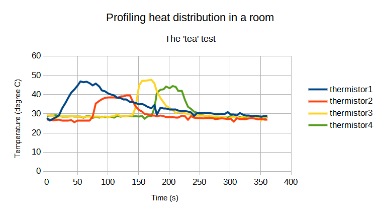
Yeah, I will admit that it wasn't the absolutely first test - I'm skipping ahead my grief with some initial debugging and incorrect temperature readings varying from -273 to 300 degree C because of broken transistor, etc. etc. In the end though, I was able to get it working reliably such that I could get a good set of data. Here is the snippet of what I recorded for a few minutes by touching the tea mug with the thermistors one by one.
Timestamp,thermistor1,thermistor2,thermistor3,thermistor4
1662975659,27.88,26.94,29.28,28.90
1662975659,27.68,27.06,29.20,28.85
1662975664,26.45,26.94,28.95,28.98
1662975669,27.37,26.52,28.92,28.98
1662975674,28.17,26.73,27.74,29.22
1662975679,29.18,26.90,28.72,28.80
1662975684,32.80,26.55,28.65,28.62
1662975689,35.38,26.55,28.58,28.45
1662975694,38.30,26.52,28.58,28.56
1662975699,41.04,26.67,28.92,28.66
1662975704,42.61,25.59,28.49,28.53
1662975709,44.53,26.31,28.42,28.61
1662975714,46.81,26.54,28.39,28.61
1662975719,46.39,26.52,28.33,27.92
1662975724,46.66,26.38,28.61,28.69
1662975729,45.90,26.47,28.61,28.69
1662975734,44.72,28.52,28.60,27.83
1662975739,45.71,35.31,28.60,28.37
1662975745,44.10,36.70,28.53,27.97
1662975749,42.13,37.51,28.06,28.46
1662975754,41.70,38.27,28.58,28.38
1662975760,40.43,38.54,28.11,28.38
1662975764,40.02,38.47,28.60,28.43
1662975769,39.52,38.54,28.72,27.94
1662975774,38.39,38.24,29.67,28.85
1662975780,38.12,39.04,28.71,28.46
1662975784,37.53,39.06,28.96,28.88
1662975789,37.33,39.49,28.77,28.83
1662975795,36.21,39.66,29.06,28.86
1662975799,36.04,36.83,29.14,28.61
1662975804,35.62,33.90,33.10,28.72
1662975810,34.91,31.93,44.77,28.54
1662975815,35.10,31.07,47.01,28.82
1662975819,34.51,29.86,47.01,27.36
1662975824,33.55,29.62,47.33,28.64
1662975830,32.83,29.14,47.70,28.67
1662975835,34.53,28.96,45.82,32.80
1662975839,29.50,28.68,41.63,40.89
1662975845,33.16,29.03,38.14,42.49
1662975850,32.73,28.74,35.92,42.72
1662975854,32.70,28.34,34.15,44.14
1662975860,32.24,28.23,32.96,43.28
1662975865,32.14,28.28,31.92,44.40
1662975870,32.29,28.00,30.35,43.95
1662975874,31.65,28.00,30.94,41.89
1662975880,31.30,28.96,30.84,42.01
1662975885,31.42,28.72,30.19,37.17
1662975890,31.10,26.83,29.86,33.64
1662975895,30.69,28.74,29.59,32.49
1662975900,28.86,27.91,28.65,31.03
1662975905,30.45,27.78,29.11,30.52
1662975909,30.38,27.71,29.03,29.83
1662975915,30.50,27.59,29.08,29.15
1662975920,30.43,27.62,28.77,28.69
1662975925,30.45,27.62,29.04,28.96
1662975930,30.09,27.77,28.42,28.26
1662975935,29.74,27.18,28.47,27.80
1662975940,29.74,27.36,28.45,28.08
1662975945,29.86,27.61,28.23,27.77
1662975950,29.90,27.43,28.28,27.96
1662975955,30.86,27.20,27.07,27.97
1662975960,29.62,27.41,28.11,28.78
1662975965,29.57,25.85,28.20,28.34
1662975970,29.09,27.64,28.00,27.77
1662975975,30.36,27.25,27.74,28.26
1662975980,29.50,27.32,28.44,28.24
1662975985,29.13,27.11,28.45,28.37
1662975990,29.06,27.53,28.30,28.24
1662975995,28.69,27.68,28.11,28.32
1662976000,28.97,27.41,28.12,28.35
1662976005,28.69,27.02,28.14,27.75
1662976010,28.49,27.30,26.44,28.26
1662976015,28.83,26.99,28.38,27.58
1662976020,28.67,27.02,28.06,28.35
With this being a success in getting the setup ready, I have installed them in my room and collecting the data as I write this blog!
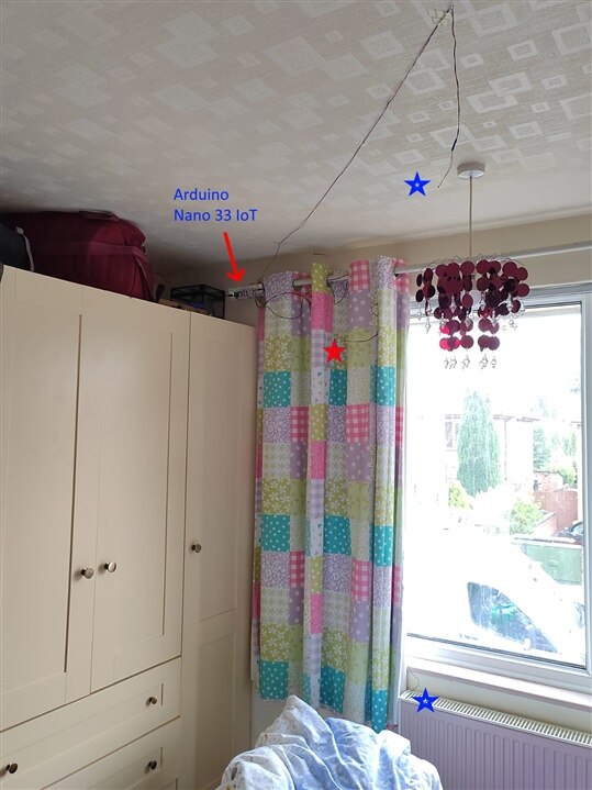
Thermistor locations are indicated by stars - thermistor1 (ring thermistor) on the heater, thermistor2 hanging from the ceiling, thermistor3 on the inside of the curtain and thermistor4 on the outside of the curtain facing the window. The picture shows curtains open but obviously at the time of measurements, I will keep the curtains closed.
OK so that was a looooong blog on the setup but look out for my final blog with the data that I will gather!
-

michaelkellett
-
Cancel
-
Vote Up
0
Vote Down
-
-
Sign in to reply
-
More
-
Cancel
Comment-

michaelkellett
-
Cancel
-
Vote Up
0
Vote Down
-
-
Sign in to reply
-
More
-
Cancel
Children