


Recap
I am building a robotic system that identifies the charging port on an EV and automatically moves a charger arm to plug the charger in.
Past Forum Posts:
Plan change: no more 3D printer gantry
In Part 1 the plan was to repurpose my old AnyCubic Mega i3 3D printer as a gantry robot - solid mechanics, motors and lead screws already working, It just needed a new job. I've dropped that idea. One simple reason: I just couldn't let myself strip it apart. Maybe I am too emotionally attached to the first 3D printer or maybe because I can actually still use the printer as a printer.
So the new plan is a tracked "Devastator" tank chassis by DFRobot that drives itself over to the car and reaches out to touch the Charging once it's close enough, rather than a fixed machine the car has to line up with. More travel, more forgiveness, and I get my printer back. Now, This Devastator tank i something i gave to my Nephew an year back. I wanted to use it for my Spring clean project but he was using it. These days school kids are doing engineering level projects. But During his experiments, he did end up burning the Yellow BO motor. Experience is the best teacher. That will teach him not to torture the BO motors to 12V. So I ordered an alternative Blue Metal geared motor to replace it in exchange for him letting me borrow the tank. Best deal ever.
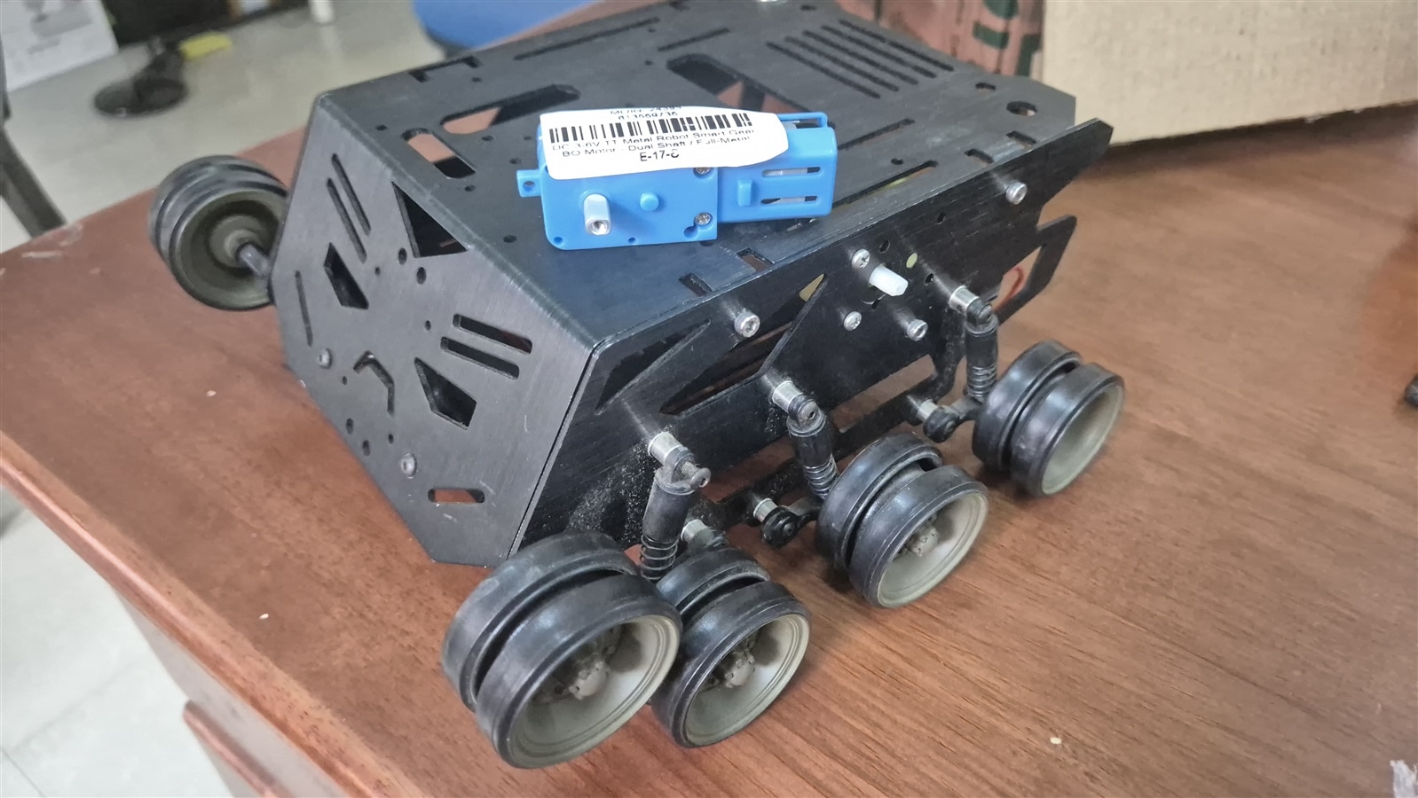 Devastator Tank with the replacement motor on top
Giving back my EnderS1 Pro his Klipper back
Part 2's prototype ran on a Raspberry Pi, using picamera2 and a CSI camera. Since then I moved all of the vision code to a newly purchased Radxa Q6A instead. The reason: I needed the RPi back. It's the board running Klipper (Mainsail OS) for my ender S1 Pro, and I'd been borrowing it for this project in the meantime. And I just thought RadXa is better than Rpi. Why? Here are my points of comparison.
| RPi 4 | RPi 5 | Radxa Q6A | |
|---|---|---|---|
| SoC | Broadcom BCM2711 | Broadcom BCM2712 | Qualcomm QCS6490 |
| CPU | 4x Cortex-A72 @ 1.5GHz | 4x Cortex-A76 @ 2.4GHz | 8x Kryo 670 (Cortex-A78/A55) up to ~2.7GHz |
| RAM | up to 8GB LPDDR4 | up to 8GB LPDDR4X |
LPDDR5, module-dependent |
| AI accel | none | none onboard | Hexagon NPU, ~12 TOPS |
| Camera interface | 1x CSI-2 | 2x CSI/DSI |
MIPI CSI available, but I'm using USB/UVC instead |
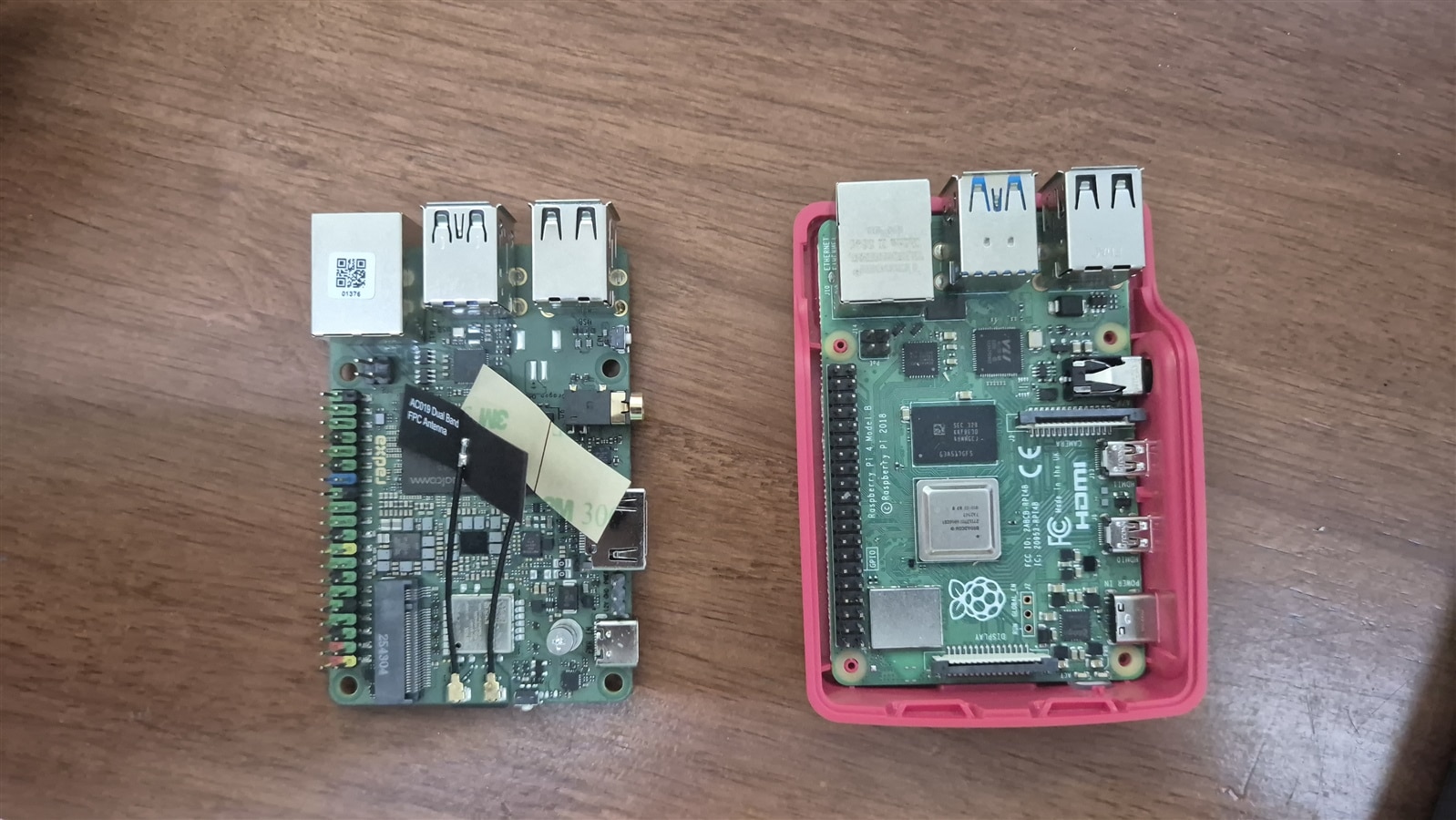
Radxa on Left and Rpi 4 on right
With RAM Pricing driving up the cost of Raspberry Pi way more than other SBC (Do checkout this Video by Jeff Geerling, This video came the day i started writing draft for this post: https://www.youtube.com/watch?v=53AkaYvw63U) , TLDR, I was reluctant to get an RPI. But very quick internet research made me finalize on the Q6A mainly because the Q6A's NPU is a genuinely different category of hardware - Cortex cores are Cortex cores, but a dedicated Hexagon NPU means headroom for heavier CV/ML later without re-architecting anything
Camera Change: comparing four options
The RPi Camera Module v1.3 from Part 2 worked, and was quite adequate for the gantry based idea. There was only a fixed volume for the ARUCO to be in, But now, the workspace is much larger and that means the camera should reliably see the aruco marker at a larger distance. Gut feeling turned out to be right, when a quick test prove that beyond 2m, the accuracy drops quite significantly. And so I had to look for alternatives. I had a Logitech HD 720. Butt that was'nt great. I really did not want to spend on a camera, Oh I forgot, Radxa I plan to use for the Make a Connection competition and after that, I plan to set it up as an AI analysis system for Analyzing data from the RPi to detect 3D print failures via Obico, Back to the camera, I asked a work client of mine who works with camera and he sent me an Waveshare IMX 335 and OV5693 Module
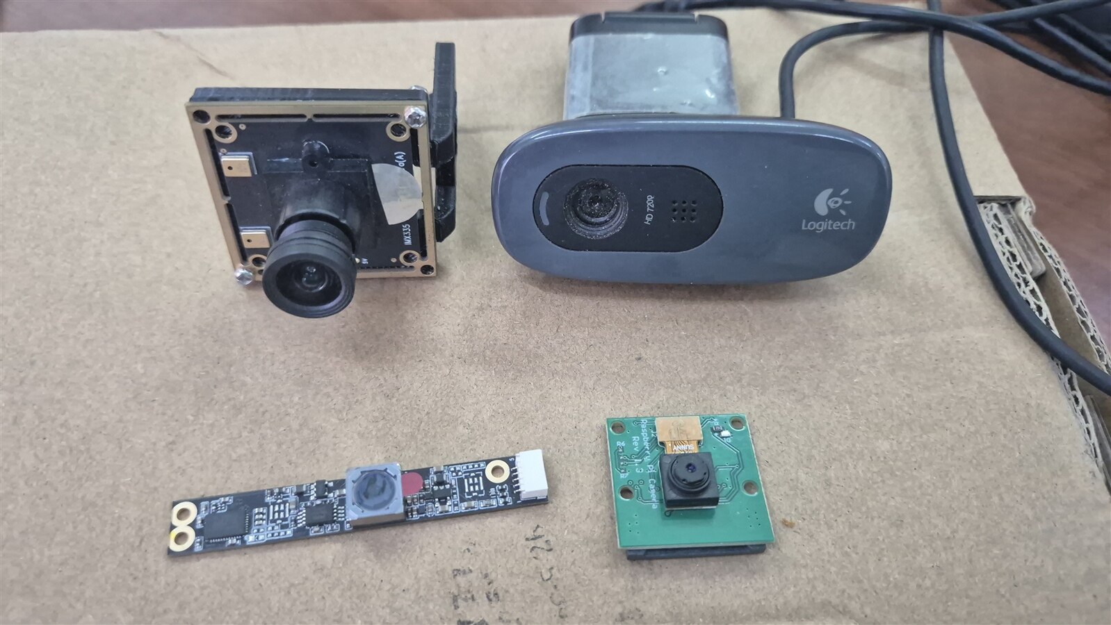
| Camera | Interface | Resolution | Notes |
|---|---|---|---|
|
Logitech HD 720p webcam (Top Right) |
USB/UVC | 1280x720 | Cheap, plug-and-play, but the ISP is tuned for video calls, not machine vision - fixed focus quality and FOV aren't great for consistent marker detection at range. |
| RPi Camera v1.3 OV5647 (Bottom Right) |
CSI | 5MP stills / 1080p30 | What I used in Part 2. Fixed focus, older sensor, weak in low light. s. |
| OV5693 (Bottm Left) |
USB | 5MP | Mostly designed as a Camera for Selfies. |
| Waveshare IMX335 (Top Left) |
USB | 5MP | Newer Sony sensor, noticeably better low light than the OV5647, sees it like any other webcam |
Moving to OpenCV 5
Around the same time I was trying out the new Raxda, OpenCV 5 launched officially in June 2026 - the first major version bump in eight years since OpenCV 4.0, bringing a radically overhauled Deep Neural Network (DNN) engine, native LLM/VLM execution, and a fresh data-type architecture. Naturally I couldn't resist installing it right away and naturally, all my Part 2 code promptly broke. So I took some time to change the code one error at a time. Thankfully, there were not much and I think the new syntax make the code shorter.
P.S. I have no idea what VLM is, I just summarized the AI Summary from Google.
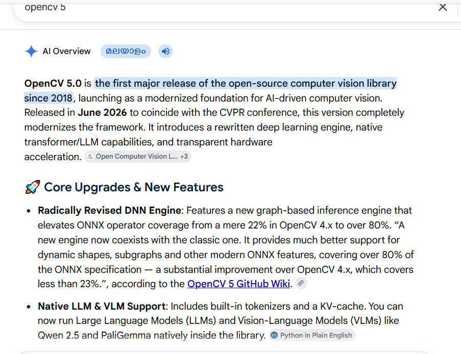
A new Arucodictionary
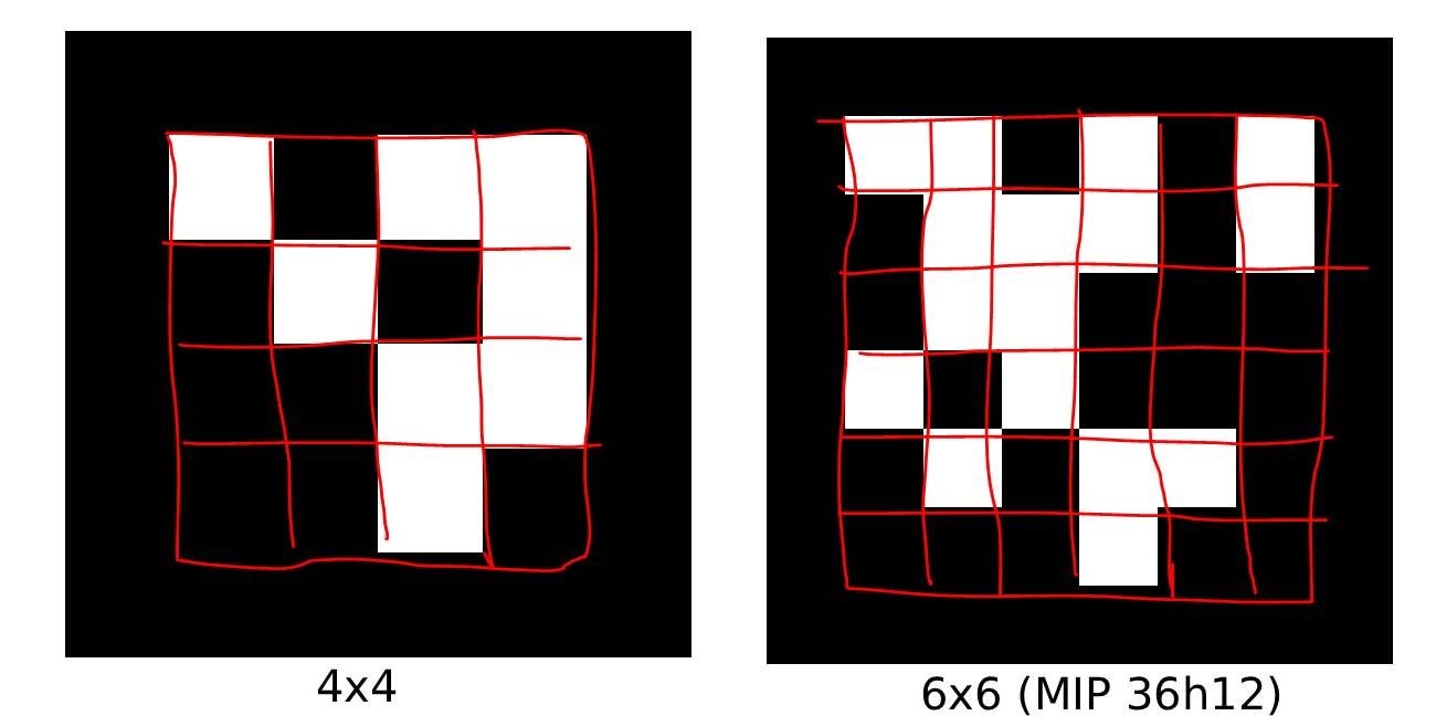
I switched ArUco dictionaries, from Aruco MIP 36h12 to DICT_4X4_50.
MIP 36h12 was never really a deliberate choice in Part 2 - I used it because the calibration board PDF I found online happened to be printed with it, and calibration board and detection markers have to agree on the same dictionary. That's a 6x6 grid of cells encoding 36 bits per marker. DICT_4X4_50 packs its ID into a 4x4 grid instead - fewer, bigger cells for the same physical marker size, which matters once the workspace got bigger and markers started showing up smaller and blurrier in frame: So, a bigger size marker with less dense ID will have better chance of being detected and more importantly distance to the marker detected correctly. Not an exact theory but with 50% more size per bits, the distance should also increase by 50%.
Improved Workflow
With the raspberry Pi, i was running headless, Initially it looked fun, but it started getting tiring due to latency of the image being sent over, difficult to debug it over SSH, so with radxa i decided to use it with a monitor. Also the radxa OS ships with a desktop environment.
The tests for accuracy and detection range
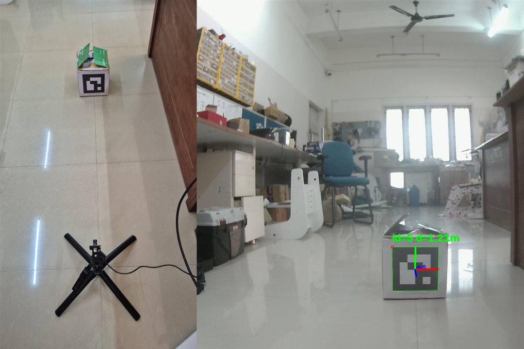
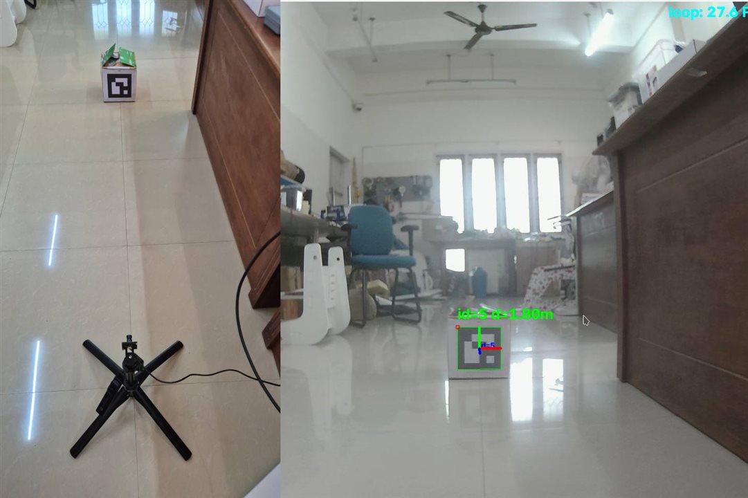
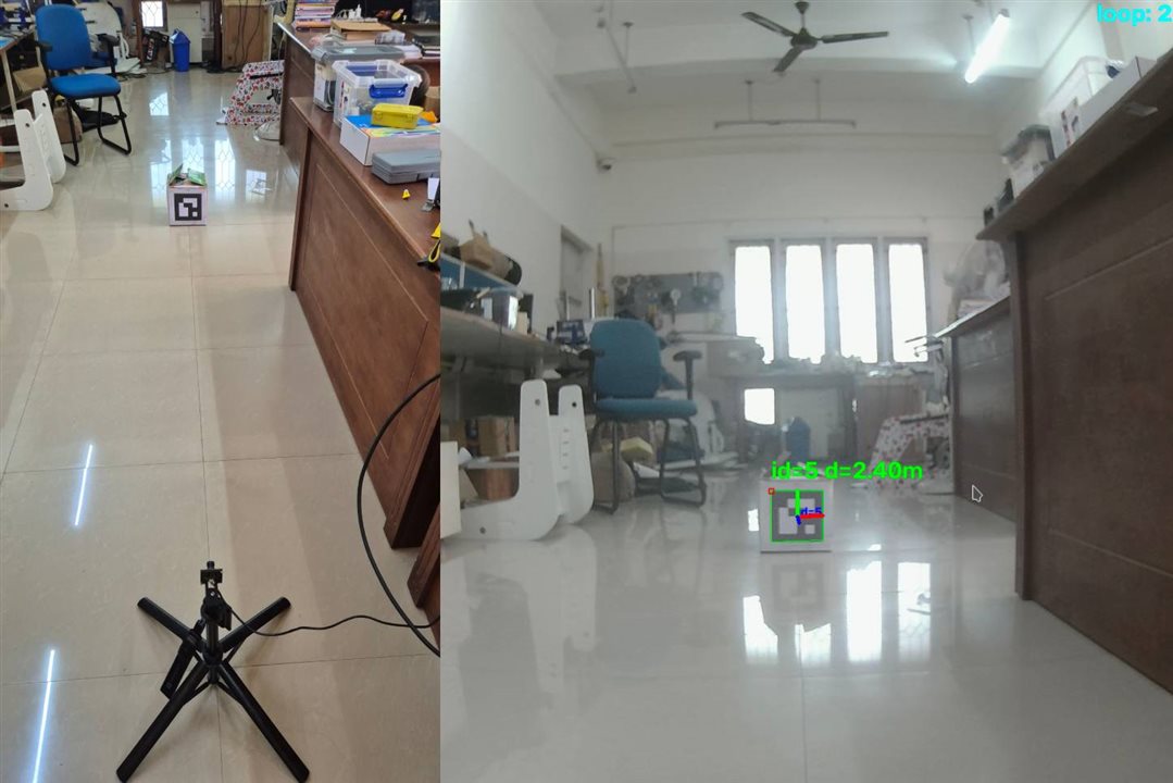
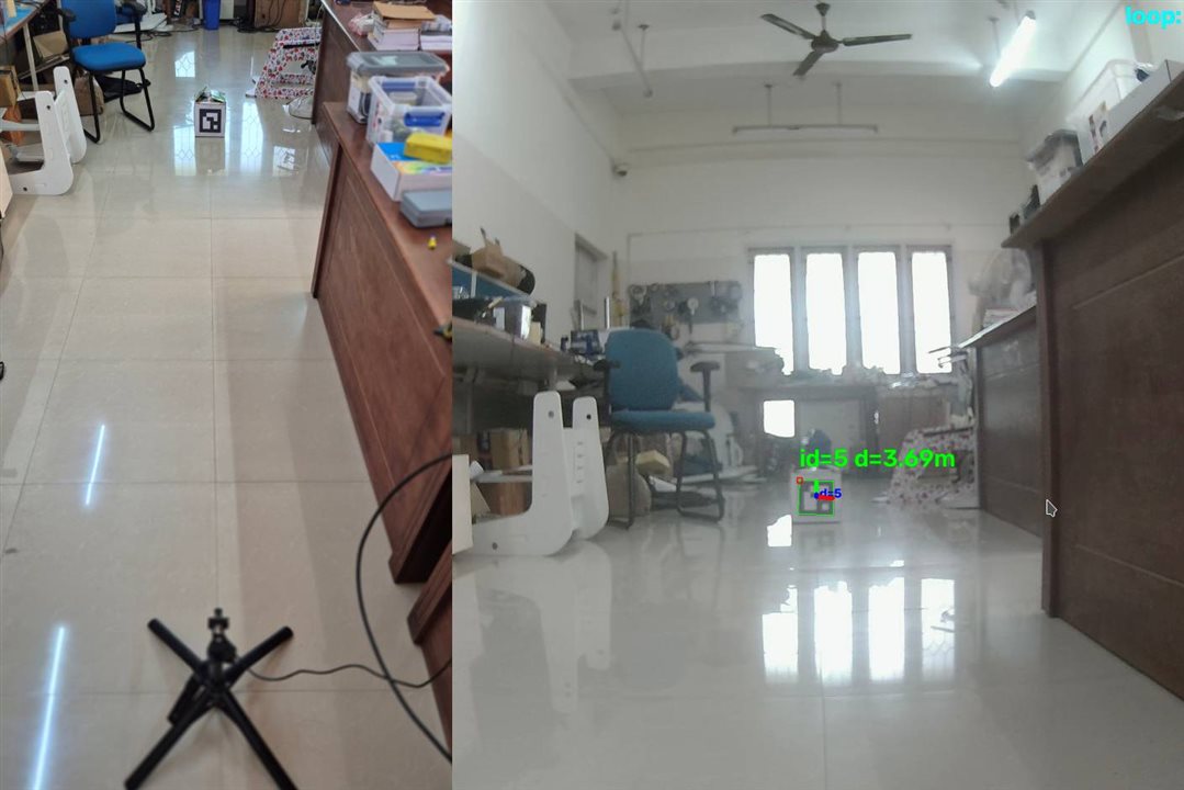
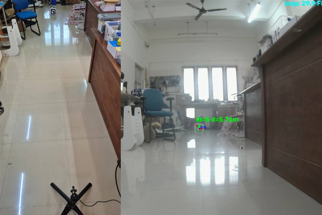
I took the whole setup to a my university lab with 60x60cm floor tiles. no tape measure required. I did measure the tiles just in case.
First question was range: how far away can this thing still reliably see the marker? Answer: 6m, comfortably past the 5m I actually need for the docking approach.
Then accuracy. I placed the marker at 60cm intervals along the tile lines and compared the reported distance against the known tile count. It tracked well throughout, but error grew with distance, worst case was about 4% and average of 3% under 2m, climbing to an max of 8% with average of 5% by 5m.
Music by Dmitrii Spis from Pixabay
| {gallery}Range Measurement |
|---|
|
1.2m:1.2M |
|
1.8m:1.8m |
|
2.4m: 2.4m |
|
3.6m:3.6m |
|
6m:6m |
|
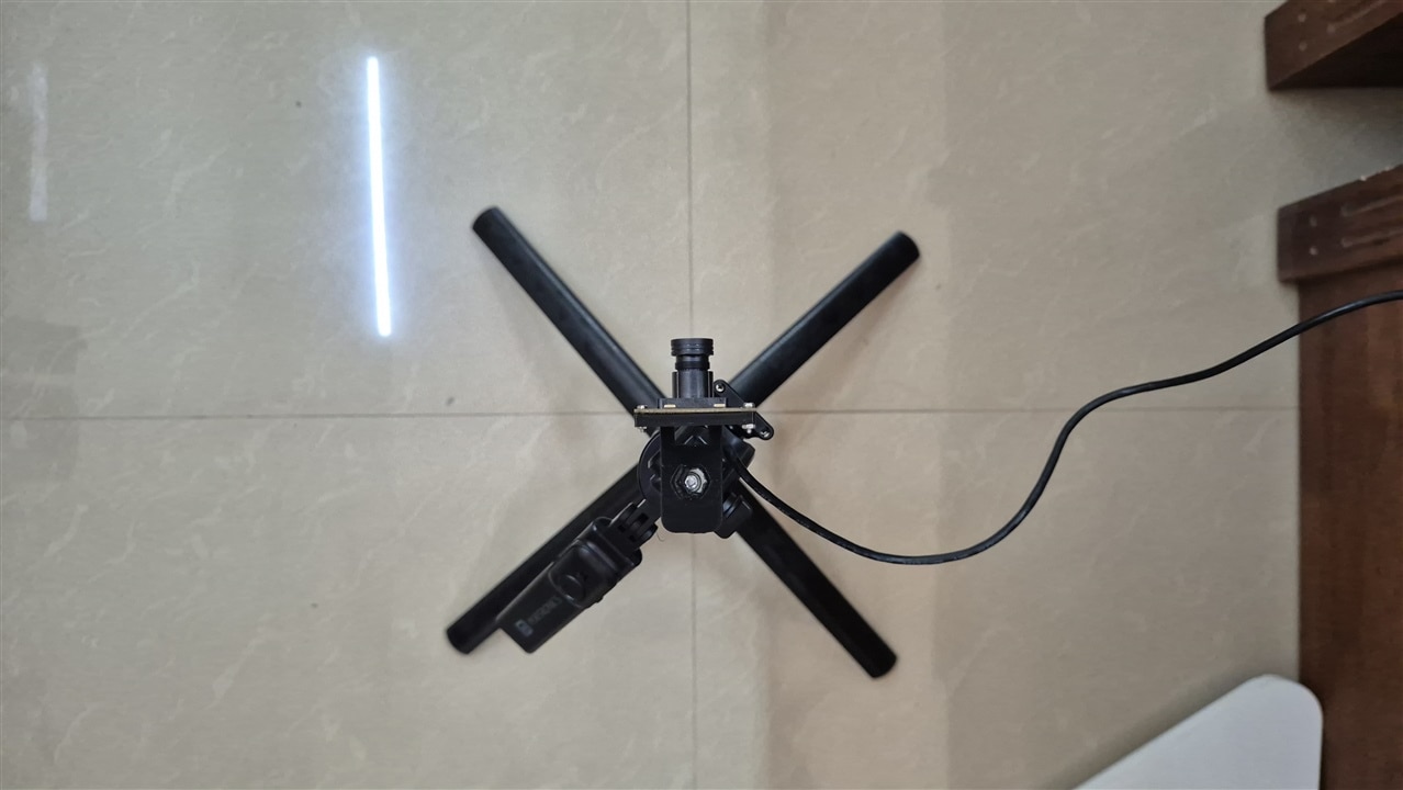
Camera Alignment: Tried by best to align the sensor along the junction of the tiles. (Parallax error applies) |
What's next
Now that the hardware is settled - Radxa Q6A, IMX335, DICT_4X4_50 - the next step is actually starting on the Devastator tank itself. Motors have arrived, Driver board is in stock with me. I have the Arduino Q.
Final Notes
Yes, I made a lot of changes, But all in the name of Improvisation. Lot's of Borrowed items, But hey what are Friends Family (and clients) for.

