element14 Community
element14 Community
    Register Log In
  • Site
  • Search
  • Log In Register
  • Community Hub
    Community Hub
    • What's New on element14
    • Feedback and Support
    • Benefits of Membership
    • Personal Blogs
    • Members Area
    • Achievement Levels
  • Learn
    Learn
    • Ask an Expert
    • eBooks
    • element14 presents
    • Learning Center
    • Tech Spotlight
    • STEM Academy
    • Webinars, Training and Events
    • Learning Groups
  • Technologies
    Technologies
    • 3D Printing
    • FPGA
    • Industrial Automation
    • Internet of Things
    • Power & Energy
    • Sensors
    • Technology Groups
  • Challenges & Projects
    Challenges & Projects
    • Design Challenges
    • element14 presents Projects
    • Project14
    • Arduino Projects
    • Raspberry Pi Projects
    • Project Groups
  • Products
    Products
    • Arduino
    • Avnet Boards Community
    • Dev Tools
    • Manufacturers
    • Multicomp Pro
    • Product Groups
    • Raspberry Pi
    • RoadTests & Reviews
  • About Us
  • Store
    Store
    • Visit Your Store
    • Choose another store...
      • Europe
      •  Austria (German)
      •  Belgium (Dutch, French)
      •  Bulgaria (Bulgarian)
      •  Czech Republic (Czech)
      •  Denmark (Danish)
      •  Estonia (Estonian)
      •  Finland (Finnish)
      •  France (French)
      •  Germany (German)
      •  Hungary (Hungarian)
      •  Ireland
      •  Israel
      •  Italy (Italian)
      •  Latvia (Latvian)
      •  
      •  Lithuania (Lithuanian)
      •  Netherlands (Dutch)
      •  Norway (Norwegian)
      •  Poland (Polish)
      •  Portugal (Portuguese)
      •  Romania (Romanian)
      •  Russia (Russian)
      •  Slovakia (Slovak)
      •  Slovenia (Slovenian)
      •  Spain (Spanish)
      •  Sweden (Swedish)
      •  Switzerland(German, French)
      •  Turkey (Turkish)
      •  United Kingdom
      • Asia Pacific
      •  Australia
      •  China
      •  Hong Kong
      •  India
      •  Korea (Korean)
      •  Malaysia
      •  New Zealand
      •  Philippines
      •  Singapore
      •  Taiwan
      •  Thailand (Thai)
      • Americas
      •  Brazil (Portuguese)
      •  Canada
      •  Mexico (Spanish)
      •  United States
      Can't find the country/region you're looking for? Visit our export site or find a local distributor.
  • Translate
  • Profile
  • Settings
Design Challenges
  • Challenges & Projects
  • More
Design Challenges
Forum Mosfet heating
  • Forum
  • Documents
  • Polls
  • Files
  • Mentions
  • Sub-Groups
  • Tags
  • More
  • Cancel
  • New
Actions
  • Share
  • More
  • Cancel
Forum Thread Details
  • Replies 5 replies
  • Subscribers 5 subscribers
  • Views 1304 views
  • Users 0 members are here
  • mosfet
  • high voltage
  • heating
Related

Mosfet heating

audrialaa
audrialaa over 7 years ago

Hello Guys,


Currently I am building circuit for high voltage discharge.

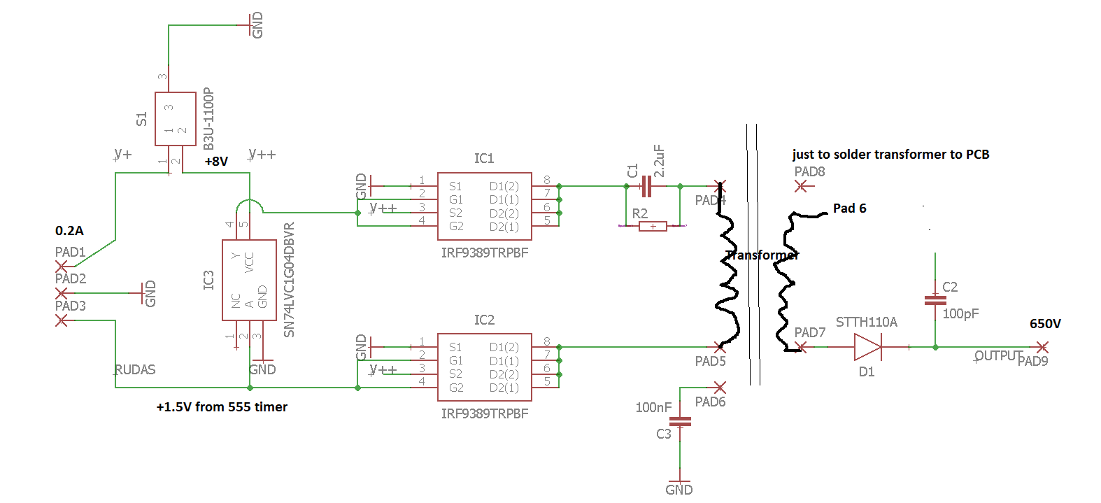
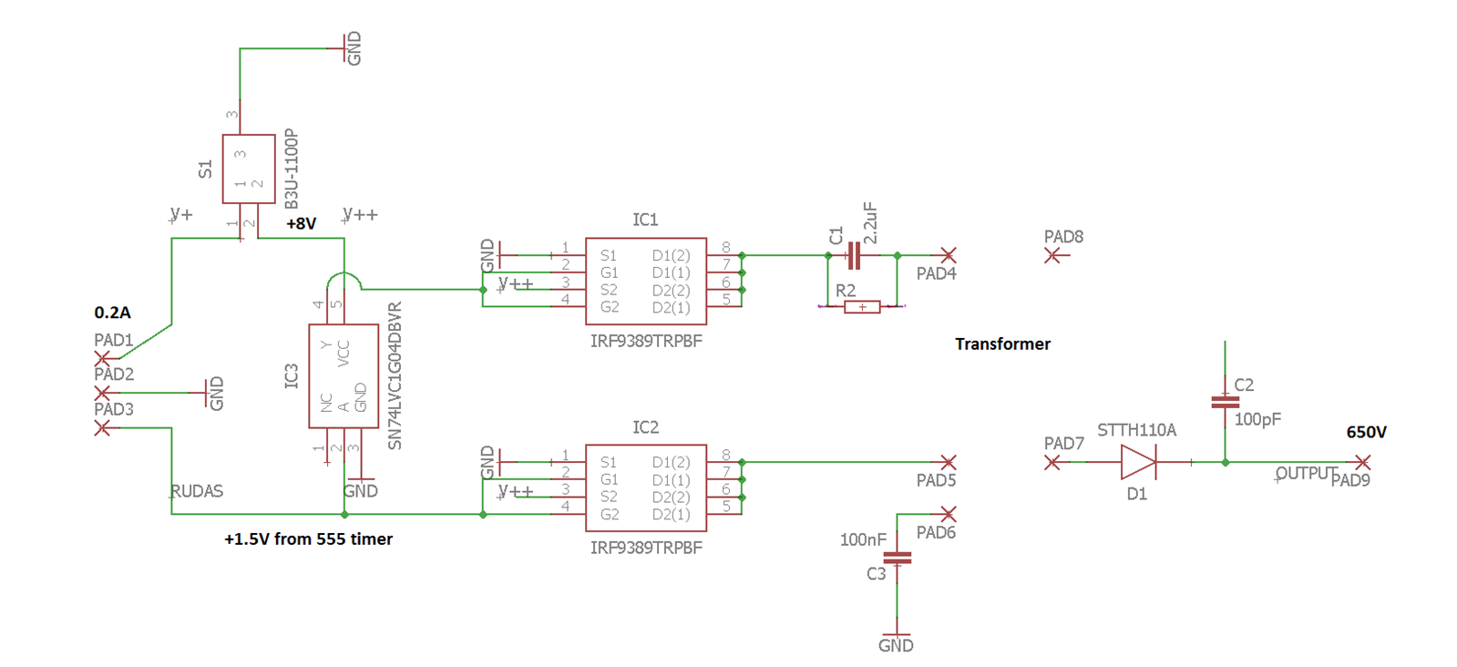
I am controlling signal using two dual channel mofsets and supplying them to the transformer ( 100 voltage multiplication).


PROBLEM 1: mosfets become very hot and I am afraid that after some time they will get damaged.

PROBLEM 2: If I put diode STTH11A the volatge output becomes very low., less than 100V.

Part of the circuit (circuit for 555 timer is pretty simple, works in abstable state  - not showed):


The SN74 is an single inverter, IRF93 Dual channel mosfets.

image


Any advices where the problems could be ?

PS: Yes I know cap in the end doesn't do anything image


Thanks for help in advance image


BS,

A

  • Sign in to reply
  • Cancel

Top Replies

  • Former Member
    Former Member over 7 years ago +5
    P channel and N channel MOSFETS are basically opposites. You are trying to drive it both on and off at the same time by trying to use them in parallel. In addition, power MOSFETS have an intrinsic body…
Parents
  • Former Member
    Former Member over 7 years ago

    P channel and N channel MOSFETS are basically opposites. You are trying to drive it both on and off at the same time by trying to use them in parallel. In addition, power MOSFETS have an intrinsic body diode, which is also hurting you. (When one MOSFET is on, the other is conducting through the body diode.) By using them in parallel, they would also attempt to be on, whether the input was high or low. (Well, either the P or N would always be on, depending on the input voltage - high or low.)


    You need to use the part with only one side of it or the other, not both tied together. (Alternatively, you could use both sides, but you still can't tie them together like that.) D1 and D2 should not touch like you have them. Potentially, based on the circuit, you could have G1 and G2 tied together, but you really need to understand how these work and be sure that it's how you want to be controlling it.


    If any of that isn't clear, let me know and I can try to explain further. I don't see enough of the circuit to be able to say anything about the diode on the transformer and why it's doing what it is. The different traces going to a pad number aren't clear what they would be doing.

    • Cancel
    • Vote Up +5 Vote Down
    • Sign in to reply
    • Cancel
  • audrialaa
    audrialaa over 7 years ago in reply to Former Member

    Thanks for an answer and explanation of dual mosfet. This is the firt project I am trying to use them and this scheme is barrowed from other device. Now I understand why this device stops to work after some time and you need to take it to warranty. Is funny, as that device is  CE certified and even getting new one it breaks - at most it keeps for two month. Seems that somebody wants to earn some extra money..


    So, in general to drive the transfomer I should use just P channel on both mosfets and I need to delay one of the signal so that the transformer could work (induce). I am correct ? As the single inverter inverts the signal from the timer and supplies it to second mosfet (timer gives pulse signal from 0V to +1.5V).

    image

    • Cancel
    • Vote Up 0 Vote Down
    • Sign in to reply
    • Cancel
  • Former Member
    Former Member over 7 years ago in reply to audrialaa

    I'm sorry, I didn't spend enough time with the datasheet and thinking about it. I misunderstood things. I think the part 9389 should be fine, as long as your transformer doesn't draw too much current and your switching frequency isn't absurdly high.


    Though in trying to understand more about what is going on, I took a look at the datasheet for your inverter, and it says it's only specced to 6.5V, though you show it as 8, which isn't good. Might still work, but I wouldn't want to have to trust it that far out of bounds. (Though your stated transformer multiplication of 100, output of 650, and input of 8 don't agree with each other, so is one of them an error, or is that just allowing for losses?)


    Otherwise, I don't know. I'm not sure the intent of the diode on the output of the transformer, but I would expect it to cause funny things to happen, since it doesn't allow current to reverse through the transformer like it wants to do.


    What kind of frequencies are you driving this at, and what is C2 attached to on the other end? What value is R2? Though I'm not sure how much that will matter compared to the inductance of the transformer.

    • Cancel
    • Vote Up 0 Vote Down
    • Sign in to reply
    • Cancel
  • audrialaa
    audrialaa over 7 years ago in reply to Former Member

    Yes, with mosfets connected like this  everything is ok. P and N channels are activated seperately.

    Also, R2 value is 1K, so I have high pass filter of 72Hz, time constant 2.2ms.


    I tried to put diode cause I want to avoid any current flowing back from transformer to the circuit. However, seems that this causes problems so, I removed it.


    I'm driving timer at around 92kHz, it is around 64% of it's duty cycle. However, the timer suppose to work in abstable state, this means that duty cycle can't be lower than 50% (it won't work if lower)

    Yes, i supply to inverter +8V, which is a bit to much, but I can't find inverters with higher supply voltage. Also, if I give signal of +1.5V to inverter and supply inverter  with +8V the output is +6.5V.


    I tested device for an hour and inverter doesn't seem to get hot or start to malfunction, I know it is not very good. Any advice how amplify signal after inverter if using lower voltage, opam ( I' am very limited in space)?


    Also, I have changed mosfets. New mosfets doesn't heat taht much, they are barely warm after an hour - I suppose it is normal.


    I tried to measure current supplied to transformer the max value I get was 200mA.

    • Cancel
    • Vote Up 0 Vote Down
    • Sign in to reply
    • Cancel
Reply
  • audrialaa
    audrialaa over 7 years ago in reply to Former Member

    Yes, with mosfets connected like this  everything is ok. P and N channels are activated seperately.

    Also, R2 value is 1K, so I have high pass filter of 72Hz, time constant 2.2ms.


    I tried to put diode cause I want to avoid any current flowing back from transformer to the circuit. However, seems that this causes problems so, I removed it.


    I'm driving timer at around 92kHz, it is around 64% of it's duty cycle. However, the timer suppose to work in abstable state, this means that duty cycle can't be lower than 50% (it won't work if lower)

    Yes, i supply to inverter +8V, which is a bit to much, but I can't find inverters with higher supply voltage. Also, if I give signal of +1.5V to inverter and supply inverter  with +8V the output is +6.5V.


    I tested device for an hour and inverter doesn't seem to get hot or start to malfunction, I know it is not very good. Any advice how amplify signal after inverter if using lower voltage, opam ( I' am very limited in space)?


    Also, I have changed mosfets. New mosfets doesn't heat taht much, they are barely warm after an hour - I suppose it is normal.


    I tried to measure current supplied to transformer the max value I get was 200mA.

    • Cancel
    • Vote Up 0 Vote Down
    • Sign in to reply
    • Cancel
Children
  • Former Member
    Former Member over 7 years ago in reply to audrialaa

    I'm a little confused. Do you mean to talk about the frequency and duty cycle as related to each other? Normally, I would want to run a transformer at as close to 50% duty cycle as possible, since any offset from that will naturally end up with extra current heating of the transformer coils for no gain in power transfer to the secondary. (And of course sine wave would be ideal, but with your capacitors and the inductance of the transformer, you might even have a decent approximation, at the end of it all.)


    I also assume that since you said you 'tried' to measure the current that it was some kind of multimeter, and it can only get an approximation of the current. I don't know of any of them that would handle something like this very well. I would give all calculations quite a bit of 'fudge factor' to make up for that. It would of course be much safer to actually see what is going on with an oscilloscope, but if you don't have one that's not helpful...


    I believe that your heating is because that is simply the wrong part for you. If you look at page 4, in Figure 8, it does not look like you're operating within the safe operating area. As a safety margin, I would try to at least be close to the boundaries for DC operation when you're wanting continuous operation like this. (You're switching back and forth, but one half of the MOSFET chip is always on.) For the N-channel, 8.5V only lets you have ~25mA, and then looking on page 9, the P-channel is slightly higher around 50mA or so.


    It just looks to me like this really can't handle any sustained current at all, unless your voltages go WAY down.


    Though if you found a different MOSFET that will do the job, then I guess this is just for curiousity's sake.


    As far as amplifying the signal, if you're trying to match shapes then an opamp with high enough gain bandwidth can be a good choice, but with it just looking at the output of an inverter, there's no point. A comparator would do a better job there, unless the slower rise times of the opamp were a bonus in your design, I guess (I'd be surprised, but technically possible.) So I'd suggest looking up a comparator with specs to match your circuit. They come in same package sizes as opamps, so it would be compact enough.

    • Cancel
    • Vote Up 0 Vote Down
    • Sign in to reply
    • Cancel
element14 Community

element14 is the first online community specifically for engineers. Connect with your peers and get expert answers to your questions.

  • Members
  • Learn
  • Technologies
  • Challenges & Projects
  • Products
  • Store
  • About Us
  • Feedback & Support
  • FAQs
  • Terms of Use
  • Privacy Policy
  • Legal and Copyright Notices
  • Sitemap
  • Cookies

An Avnet Company © 2025 Premier Farnell Limited. All Rights Reserved.

Premier Farnell Ltd, registered in England and Wales (no 00876412), registered office: Farnell House, Forge Lane, Leeds LS12 2NE.

ICP 备案号 10220084.

Follow element14

  • X
  • Facebook
  • linkedin
  • YouTube