element14 Community
element14 Community
    Register Log In
  • Site
  • Search
  • Log In Register
  • About Us
  • Community Hub
    Community Hub
    • What's New on element14
    • Feedback and Support
    • Benefits of Membership
    • Personal Blogs
    • Members Area
    • Achievement Levels
  • Learn
    Learn
    • Ask an Expert
    • eBooks
    • element14 presents
    • Learning Center
    • Tech Spotlight
    • STEM Academy
    • Webinars, Training and Events
    • Learning Groups
  • Technologies
    Technologies
    • 3D Printing
    • FPGA
    • Industrial Automation
    • Internet of Things
    • Power & Energy
    • Sensors
    • Technology Groups
  • Challenges & Projects
    Challenges & Projects
    • Design Challenges
    • element14 presents Projects
    • Project14
    • Arduino Projects
    • Raspberry Pi Projects
    • Project Groups
  • Products
    Products
    • Arduino
    • Avnet Boards Community
    • Dev Tools
    • Manufacturers
    • Multicomp Pro
    • Product Groups
    • Raspberry Pi
    • RoadTests & Reviews
  • Store
    Store
    • Visit Your Store
    • Choose another store...
      • Europe
      •  Austria (German)
      •  Belgium (Dutch, French)
      •  Bulgaria (Bulgarian)
      •  Czech Republic (Czech)
      •  Denmark (Danish)
      •  Estonia (Estonian)
      •  Finland (Finnish)
      •  France (French)
      •  Germany (German)
      •  Hungary (Hungarian)
      •  Ireland
      •  Israel
      •  Italy (Italian)
      •  Latvia (Latvian)
      •  
      •  Lithuania (Lithuanian)
      •  Netherlands (Dutch)
      •  Norway (Norwegian)
      •  Poland (Polish)
      •  Portugal (Portuguese)
      •  Romania (Romanian)
      •  Russia (Russian)
      •  Slovakia (Slovak)
      •  Slovenia (Slovenian)
      •  Spain (Spanish)
      •  Sweden (Swedish)
      •  Switzerland(German, French)
      •  Turkey (Turkish)
      •  United Kingdom
      • Asia Pacific
      •  Australia
      •  China
      •  Hong Kong
      •  India
      •  Korea (Korean)
      •  Malaysia
      •  New Zealand
      •  Philippines
      •  Singapore
      •  Taiwan
      •  Thailand (Thai)
      • Americas
      •  Brazil (Portuguese)
      •  Canada
      •  Mexico (Spanish)
      •  United States
      Can't find the country/region you're looking for? Visit our export site or find a local distributor.
  • Translate
  • Profile
  • Settings
Forget Me Not Design Challenge
  • Challenges & Projects
  • Design Challenges
  • Forget Me Not Design Challenge
  • More
  • Cancel
Forget Me Not Design Challenge
Blog Forget Me Not :  eLDERmon  Hardware Hacking #2
  • Blog
  • Forum
  • Documents
  • Files
  • Events
  • Mentions
  • Sub-Groups
  • Tags
  • More
  • Cancel
  • New
  • Share
  • More
  • Cancel
Group Actions
  • Group RSS
  • More
  • Cancel
Engagement
  • Author Author: mcb1
  • Date Created: 12 Sep 2014 10:01 AM Date Created
  • Views 964 views
  • Likes 1 like
  • Comments 0 comments
  • forget_me_not
  • b+
  • design_challenge
  • openhab
  • iot_eldermon
  • raspberryp
  • tektronix
  • eclipse
  • internet_of_things
  • enocean
  • smarthome
  • challenge
  • iot
  • enocean_pi
Related
Recommended

Forget Me Not :  eLDERmon  Hardware Hacking #2

mcb1
mcb1
12 Sep 2014

Forget Me Not :  eLDERmon  Hardware Hacking #2


This post continues with my Hardware modification to provide a 'status' indication back from RF switched Outlets


Link to other posts
Forget Me Not : eLDERmon Intro
Forget Me Not :  eLDERmon  Electrical
Forget Me Not :  eLDERmon  Outlets
Forget Me Not : eLDERmon Planning
Forget Me Not : eLDERmon Parts 1
Forget Me Not :  eLDERmon  Sponsor Parts
Forget Me Not : eLDERmon Hardware Hacking
Forget Me Not : eLDERmon GNUplot
Forget Me Not: eLDERmon Protocol
Forget Me Not : eLDERmon Hardware Hacking #2
Forget Me Not : eLDERmon Hardware Hacking #3
Forget Me Not : eLDERmon OpenHAB


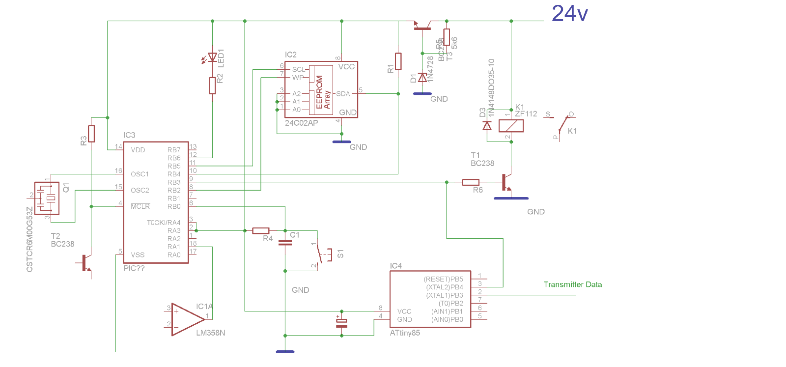
The first part of the task was tracing the circuit to find the important parts

  • Volts
  • Outputs


The main processor IC doesn't include any markings.

Luckily there is an Atmel 24C02 eeprom fitted which presumably uses the same voltage and connects to the processor.


image


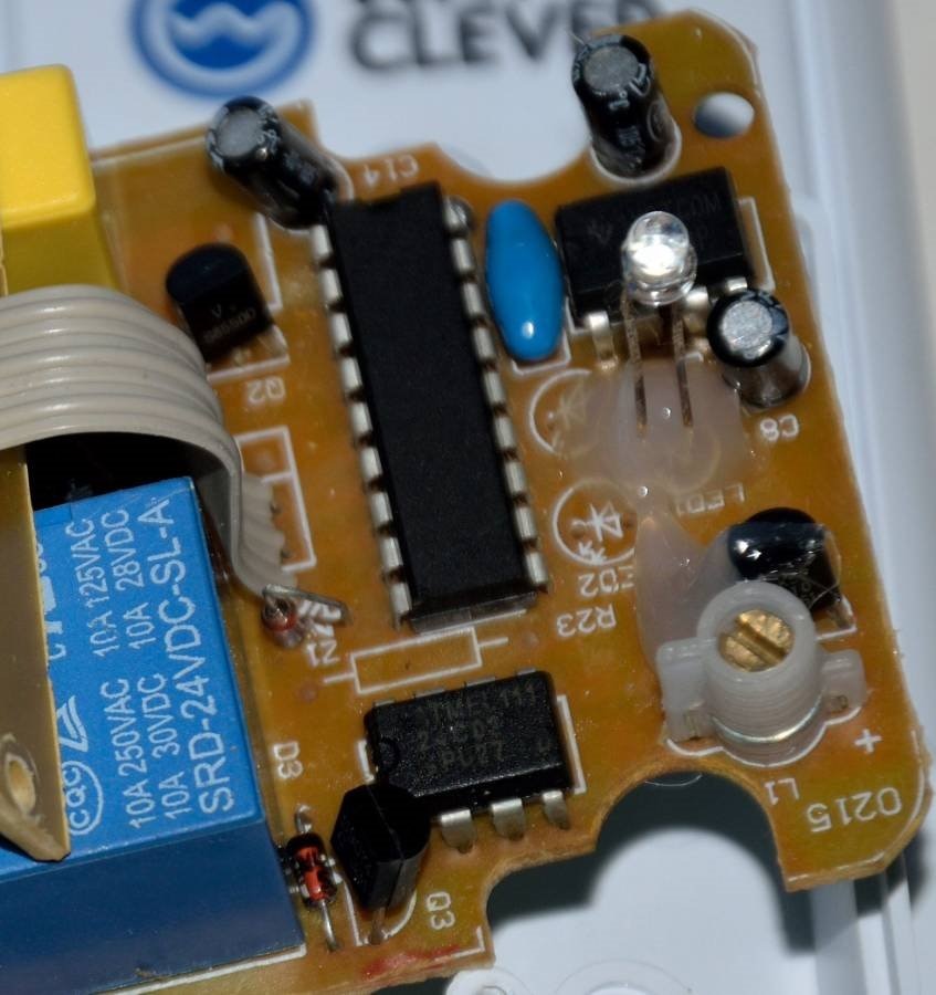
The relay is 24v, and is a good starting point to identify the voltage and ground rails.

The IC's are unlikely to be 24v, but checking against the eeprom datasheet. (8 leg PDIP), you can confirm the ground, and look for a regulator.


image

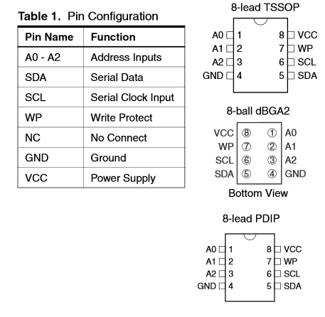
The operating voltage limits are also in the datasheet.

image

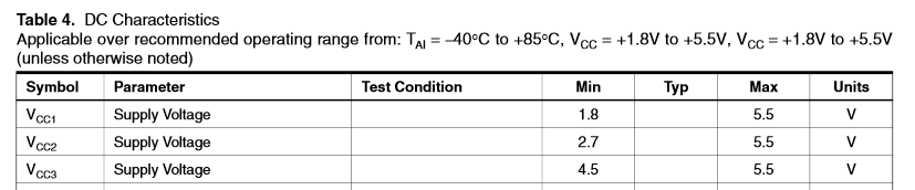
This confirms there is a regulator, and the voltage is within the ATtiny85 range, we can plan to connect to the same supply.


Tracing the circuit is a matter of identifying the part, and then tracing where each pin connects to.

It becomes easier once you know the parts, but even if you don't know what the device is, or what each pin does, you can still trace it.


Use a large piece of paper and don't worry too much about being too tidy.

Once you have enough completed (or its too messy), then start with a new piece of paper and tidy it up.

image


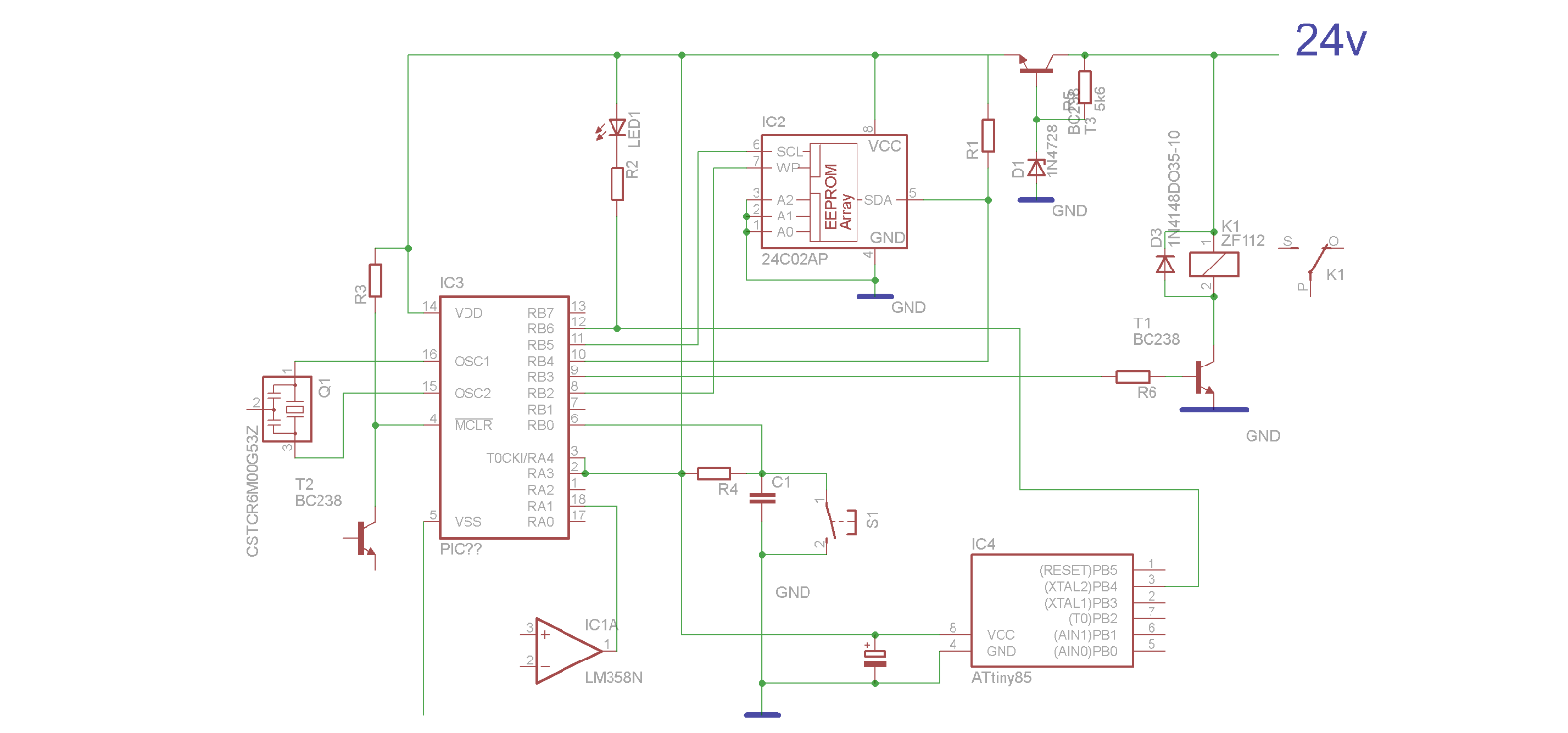
Included with the Challenge is Cadsoft Eagle, so its very useful for drawing a schematic ...providing you know the parts.

I have decided that the main control IC is a 18 pin PIC based on the voltage pins and the resonator.


Control Pin

There are two pins that change when the Outlet is ON, the relay drive and the LED.

You will note the circuit above I elected to use the LED pin.

This was because it already had a pullup (the LED), and had some extra pads available.


As I reviewed the design, it struck me that during the 'learning' mode (where you give the Outlet a code), the LED flashes at different rates.

Rather than code for this, I have decided to use the relay control pin (before the resistor).


image


ATtiny85

In my last Challenge, I had a few problems with programming these very useful devices.

In the end I used a Digispark, rather than waste too much time.

http://www.element14.com/community/groups/wireless-power-solution/blog/2014/06/08/wireless-challenge-the-other-bit-2

http://www.element14.com/community/groups/wireless-power-solution/blog/2014/06/25/wireless-challenge-beer-tap-the-other-bit--4-assembly


I made the fatal mistake of assuming ....image


I knew both the Digispark and the Orblink used the V-USB hack where a couple of 3.6v zeners and a pullup resistor provide the USB connection.

What I didn't realise is they used different pins on the ATtiny85.


So while I had programmed the raw IC correctly, when I tried placing it in the Orblink board, I couldn't talk to it.


To solve that I brought an Tiny AVR programmer

  imageimage


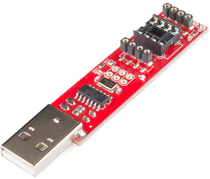
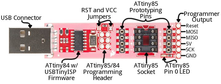
     image source https://learn.sparkfun.com/tutorials/tiny-avr-programmer-hookup-guide/


The advantage of this device is that you can use the prototyping pins to connect to the external parts without removing it.


Arduino IDE

One major advantage of the ATTtiny85 is that you can program it with the Arduino IDE, and apart from the smaller code space, the libraries work.


The ATtiny85 has no facility for an external resonator or crystal, and the clock speed is set during the programming.


image

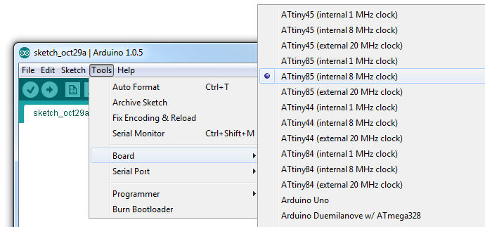
But this causes issues since most things are based around the Arduino 16MHz clock.

Even delay(500) is only a 500mS timer when the clock is 16MHz.


The images below show the simple blink program running at different clock speeds.


  imageimage

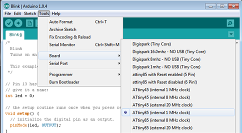
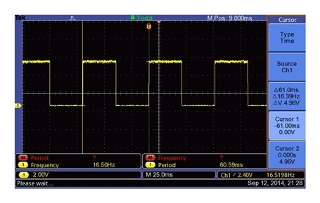
     At 1Mhz clock our 1 sec waveform is 16.5Hz


   imageimage

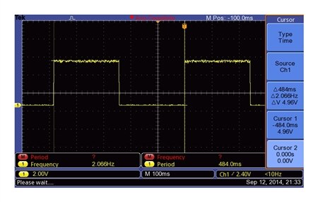
     At 8Mhz clock our 1 sec waveform is 2Hz

   imageimage

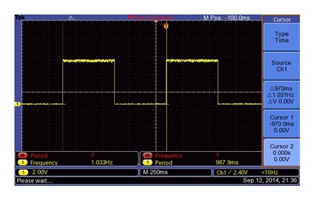
     At 16Mhz clock our 1 sec waveform is 1Hz (cursor is slightly off)


So the moral of this story is to ensure the clock speed matches, if you are using the internal libraries.


Luckily the Digispark board setting has the 16MHz clock option and is available here.

digispark:tutorials:connecting [Digistump Wiki]


The libraries all work (or have been tweaked to suit the ATtiny85) BUT the Digispark bootloader allows for the P5 to be used (the reset pin).

So unless you reprogram your ATtiny85, you should avoid using that pin.


Installation

I was hoping to have a picture of the hardware installed, but other things transpired and prevented me from doing the installation.

I will do this over the next day or so, but in the meantime Christopher usually does his weekly summary, so it's better to publish now.


Mark

  • Sign in to reply
element14 Community

element14 is the first online community specifically for engineers. Connect with your peers and get expert answers to your questions.

  • Members
  • Learn
  • Technologies
  • Challenges & Projects
  • Products
  • Store
  • About Us
  • Feedback & Support
  • FAQs
  • Terms of Use
  • Privacy Policy
  • Legal and Copyright Notices
  • Sitemap
  • Cookies

An Avnet Company © 2025 Premier Farnell Limited. All Rights Reserved.

Premier Farnell Ltd, registered in England and Wales (no 00876412), registered office: Farnell House, Forge Lane, Leeds LS12 2NE.

ICP 备案号 10220084.

Follow element14

  • X
  • Facebook
  • linkedin
  • YouTube