Previous Posts:
In The Air: Epidose 1: Introduction
In The Air: Episode 2 - Preparing for Surface Mount Work
In The Air: Episode 3 - Surface Mount Beginnings
In The Air: Episode 4 - Inductors
In The Air: Episode 5 - PCB Design
In The Air: Episode 6 - Getting Ready For PCBs
In The Air: Episode 7 - Still Getting Ready for PCBs
Update
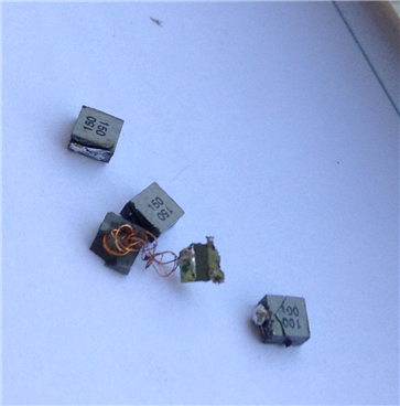
Board is complete, and not destroying components ... anymore. I went through 4 inductors troubleshooting this one. I really should get a current limited supply. Here's a picture of the inductor graveyard.
I also lost a buck regulator in the process. In fact, it was the buck regulator that originally caused the first inductor to be destroyed. There was a short from power to ground under the regulator, and that's how the first inductor got destroyed. Then, somehow, the power supply leads got reversed, and that took out another inductor. Finally, four inductors later, the board is working. These inductors are quite handy when prototyping; they act like a fuse of sorts.
Oops
Below is the Booster Pack Header pin out. I made a mistake in my original layout, because I used the I²C lines, P1 - Ref 9 & 10, and I used the PWM available from P4 - Ref 1. I'm using the PWM signal to drive a pump. If you examine the Dev Pin numbers, you'll notice that the I2C_SDA pin is the same as the PWM pin for Ref 1. The * indicates a hardware modification is required to connect the PWM, but you can't use both at the same time. So, I made a hardware change; that is, I cut the trace for the PWM from Dev Pin 2 and soldered in a jumper wire for Dev Pin 64 instead.
Figure 1: CC3200 Header Pin Out
Figure 2 shows my modification. It's a yellow wire at the bottom of the figure. If you look closely you can also see where I cut the trace beside the resistor I jumpered to. There is a second modification as well, but that's just a voltage supply mod.
Figure 2: I²C & PWM Conflict Modification. The yellow wire at the bottom of the figure is the jumper.
Pump Control
Having fixed the hardware issue, the software to control PWM was next. The CC3200 offers example code from the SDK for PWM control. I started with that example and modified it to work for Pin 64 instead of the I²C pins. I started with the wlan example and started bringing in all the functions from the PWM example that I required:
- void InitPWMModules()
- void DeInitPWMModules()
- void SetupTimerPWMMode(unsigned long ulBase, unsigned long ulTimer, unsigned long ulConfig, unsigned char ucInvert)
- void UpdateDutyCycle(unsigned long ulBase, unsigned long ulTimer, unsigned char ucLevel)
You'll likely have to add a few includes and a few defines, but it's relatively simple.
pinmux.c should have these lines in it:
//
// Enable Peripheral Clocks
//
MAP_PRCMPeripheralClkEnable(PRCM_GPIOA1, PRCM_RUN_MODE_CLK);

//
// Configure PIN_64 for GPIOOutput
//
MAP_PinTypeGPIO(PIN_64, PIN_MODE_0, false);
MAP_GPIODirModeSet(GPIOA1_BASE, 0x2, GPIO_DIR_MODE_OUT);
Your main program will have something like this implemented:
InitPWMModules();
UpdateDutyCycle(TIMERA2_BASE, TIMER_B, pwmValue);
I wanted to be able to control the PWM duty cycle from one of the kit's switches, so I used the button_if example from the common directory in the SDK, and this is where all my problems started. I could read the button pin, but not get any interrupt from it. I searched for quite a while on this topic, and I happened upon a forum where a guy said that in order for his interrupts to work he had to use UniFlash to completely clear the ROM on his board. So, I did this and the interrupts now work. Apparently, there can be conflict between using the OSI examples and mixing them with the examples from common. I'm not sure what happens or why, but just be warned.
Demo
Here's a video of the interrupt driven PWM control working.
And a video of my modification explanation.
Until next time ...


Top Comments
-

fvan
-
Cancel
-
Vote Up
0
Vote Down
-
-
Sign in to reply
-
More
-
Cancel
Comment-

fvan
-
Cancel
-
Vote Up
0
Vote Down
-
-
Sign in to reply
-
More
-
Cancel
Children