element14 Community
element14 Community
    Register Log In
  • Site
  • Search
  • Log In Register
  • About Us
  • Community Hub
    Community Hub
    • What's New on element14
    • Feedback and Support
    • Benefits of Membership
    • Personal Blogs
    • Members Area
    • Achievement Levels
  • Learn
    Learn
    • Ask an Expert
    • eBooks
    • element14 presents
    • Learning Center
    • Tech Spotlight
    • STEM Academy
    • Webinars, Training and Events
    • Learning Groups
  • Technologies
    Technologies
    • 3D Printing
    • FPGA
    • Industrial Automation
    • Internet of Things
    • Power & Energy
    • Sensors
    • Technology Groups
  • Challenges & Projects
    Challenges & Projects
    • Design Challenges
    • element14 presents Projects
    • Project14
    • Arduino Projects
    • Raspberry Pi Projects
    • Project Groups
  • Products
    Products
    • Arduino
    • Avnet Boards Community
    • Dev Tools
    • Manufacturers
    • Multicomp Pro
    • Product Groups
    • Raspberry Pi
    • RoadTests & Reviews
  • Store
    Store
    • Visit Your Store
    • Choose another store...
      • Europe
      •  Austria (German)
      •  Belgium (Dutch, French)
      •  Bulgaria (Bulgarian)
      •  Czech Republic (Czech)
      •  Denmark (Danish)
      •  Estonia (Estonian)
      •  Finland (Finnish)
      •  France (French)
      •  Germany (German)
      •  Hungary (Hungarian)
      •  Ireland
      •  Israel
      •  Italy (Italian)
      •  Latvia (Latvian)
      •  
      •  Lithuania (Lithuanian)
      •  Netherlands (Dutch)
      •  Norway (Norwegian)
      •  Poland (Polish)
      •  Portugal (Portuguese)
      •  Romania (Romanian)
      •  Russia (Russian)
      •  Slovakia (Slovak)
      •  Slovenia (Slovenian)
      •  Spain (Spanish)
      •  Sweden (Swedish)
      •  Switzerland(German, French)
      •  Turkey (Turkish)
      •  United Kingdom
      • Asia Pacific
      •  Australia
      •  China
      •  Hong Kong
      •  India
      •  Korea (Korean)
      •  Malaysia
      •  New Zealand
      •  Philippines
      •  Singapore
      •  Taiwan
      •  Thailand (Thai)
      • Americas
      •  Brazil (Portuguese)
      •  Canada
      •  Mexico (Spanish)
      •  United States
      Can't find the country/region you're looking for? Visit our export site or find a local distributor.
  • Translate
  • Profile
  • Settings
In the Air Design Challenge
  • Challenges & Projects
  • Design Challenges
  • In the Air Design Challenge
  • More
  • Cancel
In the Air Design Challenge
Blog In The Air: Episode 9: Pump Control
  • Blog
  • Forum
  • Documents
  • Polls
  • Files
  • Events
  • Mentions
  • Sub-Groups
  • Tags
  • More
  • Cancel
  • New
  • Share
  • More
  • Cancel
Group Actions
  • Group RSS
  • More
  • Cancel
Engagement
  • Author Author: michaelwylie
  • Date Created: 22 Feb 2015 5:46 AM Date Created
  • Views 1904 views
  • Likes 5 likes
  • Comments 6 comments
  • iot_particle_counter
  • pwm
  • in_the_air
Related
Recommended

In The Air: Episode 9: Pump Control

michaelwylie
michaelwylie
22 Feb 2015

Previous Posts:

In The Air: Epidose 1: Introduction

In The Air: Episode 2 - Preparing for Surface Mount Work

In The Air: Episode 3 - Surface Mount Beginnings

In The Air: Episode 4 - Inductors

In The Air: Episode 5 - PCB Design

In The Air: Episode 6 - Getting Ready For PCBs

In The Air: Episode 7 - Still Getting Ready for PCBs

In The Air: Episode 8


Update

Board is complete, and not destroying components ... anymore. I went through 4 inductors troubleshooting this one. I really should get a current limited supply. Here's a picture of the inductor graveyard.

image

I also lost a buck regulator in the process. In fact, it was the buck regulator that originally caused the first inductor to be destroyed. There was a short from power to ground under the regulator, and that's how the first inductor got destroyed. Then, somehow, the power supply leads got reversed, and that took out another inductor. Finally, four inductors later, the board is working. These inductors are quite handy when prototyping; they act like a fuse of sorts.


Oops


Below is the Booster Pack Header pin out. I made a mistake in my original layout, because I used the I²C lines, P1 - Ref 9 & 10, and I used the PWM available from P4 - Ref 1. I'm using the PWM signal to drive a pump. If you examine the Dev Pin numbers, you'll notice that the I2C_SDA pin is the same as the PWM pin for Ref 1. The * indicates a hardware modification is required to connect the PWM, but you can't use both at the same time. So, I made a hardware change; that is, I cut the trace for the PWM from Dev Pin 2 and soldered in a jumper wire for Dev Pin 64 instead.


Figure 1: CC3200 Header Pin Outimage


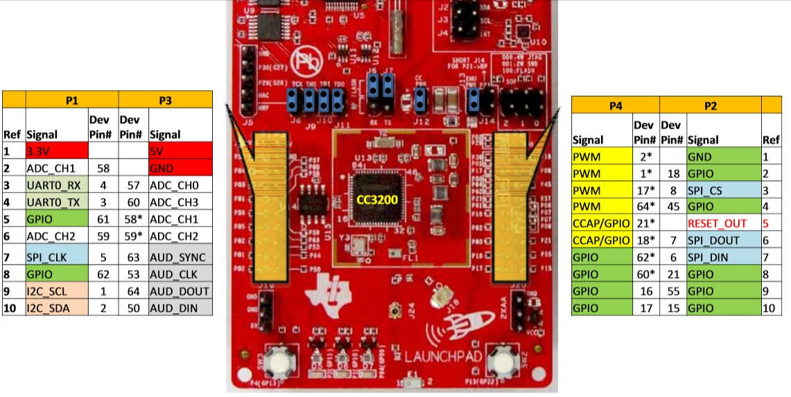
Figure 2 shows my modification. It's a yellow wire at the bottom of the figure. If you look closely you can also see where I cut the trace beside the resistor I jumpered to. There is a second modification as well, but that's just a voltage supply mod.


image

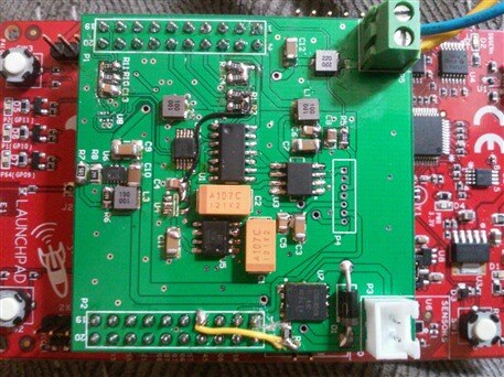
Figure 2: I²C & PWM Conflict Modification. The yellow wire at the bottom of the figure is the jumper.


Pump Control


Having fixed the hardware issue, the software to control PWM was next. The CC3200 offers example code from the SDK for PWM control. I started with that example and modified it to work for Pin 64 instead of the I²C pins. I started with the wlan example and started bringing in all the functions from the PWM example that I required:

  • void InitPWMModules()
  • void DeInitPWMModules()
  • void SetupTimerPWMMode(unsigned long ulBase, unsigned long ulTimer, unsigned long ulConfig, unsigned char ucInvert)
  • void UpdateDutyCycle(unsigned long ulBase, unsigned long ulTimer, unsigned char ucLevel)


You'll likely have to add a few includes and a few defines, but it's relatively simple.


pinmux.c should have these lines in it:

//
// Enable Peripheral Clocks
//
MAP_PRCMPeripheralClkEnable(PRCM_GPIOA1, PRCM_RUN_MODE_CLK);

//
// Configure PIN_64 for GPIOOutput
//
MAP_PinTypeGPIO(PIN_64, PIN_MODE_0, false);
MAP_GPIODirModeSet(GPIOA1_BASE, 0x2, GPIO_DIR_MODE_OUT);


Your main program will have something like this implemented:

InitPWMModules();
UpdateDutyCycle(TIMERA2_BASE, TIMER_B, pwmValue);


I wanted to be able to control the PWM duty cycle from one of the kit's switches, so I used the button_if example from the common directory in the SDK, and this is where all my problems started. I could read the button pin, but not get any interrupt from it. I searched for quite a while on this topic, and I happened upon a forum where a guy said that in order for his interrupts to work he had to use UniFlash to completely clear the ROM on his board. So, I did this and the interrupts now work. Apparently, there can be conflict between using the OSI examples and mixing them with the examples from common. I'm not sure what happens or why, but just be warned.


Demo


Here's a video of the interrupt driven PWM control working.


You don't have permission to edit metadata of this video.
Edit media
x
image
Upload Preview
image


And a video of my modification explanation.


You don't have permission to edit metadata of this video.
Edit media
x
image
Upload Preview
image


Until next time ...

  • Sign in to reply

Top Comments

  • michaelwylie
    michaelwylie over 10 years ago in reply to clem57 +1
    Thanks. It's funny you should mention that. In the lab where I studied we would work with small stuff all the time (high frequency work). One of the students who worked there before me went to med school…
  • michaelwylie
    michaelwylie over 10 years ago in reply to tomaja +1
    Some of them weren't obvious. I did a continuity check across it to test. Too much rework can be a problem, sometimes you gotta get a new board ...
  • michaelwylie
    michaelwylie over 10 years ago in reply to tomaja

    Some of them weren't obvious. I did a continuity check across it to test. Too much rework can be a problem, sometimes you gotta get a new board ...

    • Cancel
    • Vote Up +1 Vote Down
    • Sign in to reply
    • More
    • Cancel
  • tomaja
    tomaja over 10 years ago

    I made a similar mistake with PCB.

    I selected one of the UART pins for use with dust sensor so I didn't have Serial debugging capability until I assigned a different pin by using the same method as you did image Since I plan to use the UART for communication with FRAM board later, I had to modify the board, it's not just for the sake of debugging.


    Do these inductors always blow so obviously like this or they can burn without showing visible marks? Hopefully my inductor is fine, I only had one (I didn't receive the kits), I will have to check it.

    My battery charging circuit is still not working. I tried to re-solder BQ25504 a couple of times (I ordered 3 sample ICs from TI, I will probably have to do it again). I also checked for shorts with multimeter but it all seems fine. It's really hard to resolve the problem with so small device... I'm afraid that the PCB pads might peel off due to too many reworks image - It's getting very frustrating.


    Dragan

    • Cancel
    • Vote Up 0 Vote Down
    • Sign in to reply
    • More
    • Cancel
  • michaelwylie
    michaelwylie over 10 years ago in reply to clem57

    Thanks. It's funny you should mention that. In the lab where I studied we would work with small stuff all the time (high frequency work). One of the students who worked there before me went to med school afterwards and specialized in, of all things, micro-surgery. Great observation.

    • Cancel
    • Vote Up +1 Vote Down
    • Sign in to reply
    • More
    • Cancel
  • michaelwylie
    michaelwylie over 10 years ago in reply to fvan

    Thanks. The I²C is driving me nuts now. Device won't respond to its address.

    • Cancel
    • Vote Up 0 Vote Down
    • Sign in to reply
    • More
    • Cancel
  • clem57
    clem57 over 10 years ago

    Wow! The detailed work you do Mike is fantastic on solder paste rework and heat flowing for the SMT, Looks like nerve surgery but on tiny leads instead. The key seems to be the right tools and techniques. I like the videoimage

    • Cancel
    • Vote Up 0 Vote Down
    • Sign in to reply
    • More
    • Cancel
>
element14 Community

element14 is the first online community specifically for engineers. Connect with your peers and get expert answers to your questions.

  • Members
  • Learn
  • Technologies
  • Challenges & Projects
  • Products
  • Store
  • About Us
  • Feedback & Support
  • FAQs
  • Terms of Use
  • Privacy Policy
  • Legal and Copyright Notices
  • Sitemap
  • Cookies

An Avnet Company © 2025 Premier Farnell Limited. All Rights Reserved.

Premier Farnell Ltd, registered in England and Wales (no 00876412), registered office: Farnell House, Forge Lane, Leeds LS12 2NE.

ICP 备案号 10220084.

Follow element14

  • X
  • Facebook
  • linkedin
  • YouTube