


![Blog 10 - Bringing the hardware all together - Part 2 [updated]](https://community-storage.element14.com/communityserver-components-secureimagefileviewer/communityserver/blogs/components/weblogfiles/00/00/00/03/42/70443.missionpatch.PNG-1440x400x2.png?sv=2016-05-31&sr=b&sig=8KILER9LN2TNjT5qIvHRtQg5Z2z%2FRhaUMo%2FmDeuj0Jc%3D&se=2026-03-30T23%3A59%3A59Z&sp=r&_=uQes5V6ajo62IuO+MvnSHQ==)
After a little break in the new year and the full force of back to work I have finally had some time to set about documenting part 2 of my build.
The blog so far:
Links should open new tabs / windows
Sections 1-4. Initial thoughts, requirements,excitement and unboxing.
- Blog 1 - The what and why (Garden pond monitoring Background and Introductions)
- Blog 2 - My Method or WWHW (What, Why, How, When)
- Blog 3 - excited as its on the way
- Blog 4 - Arrivals, Unboxing, Github and requirements
Sections 5 - 9, design build, code and test, so much testing
- Blog 5 - Getting started with the MKR 1300 (and LoRa Sender Starting LoRa failed!)
- Blog 6 - The Soak Test UPDATE 2 (Test 3 - sump pump and soak)
- Blog 7 - Sensors, connections and starting some code - draft / wip
- Blog 8 - Measure, send, receive, transform, store, display (updated with code)
- Blog 9 - Bringing the hardware all together - Part 1 (updated)
This is Blog 10, part 2 of the build progress as the final step before going live and outside.
Blog 11, will be about commissioning and then collecting real world data
The final blog number 12 will wrap up and cover the following:
- Original functional and non functional specifications - mapped to what was done and tested.
- Orignal design vs final design - retrospective on the good, the bad, the confused.
- What could have been done better and lesson learnt.
- Data to insight - now I am measuring what can I do with that information
- Final bill of materials, for all parts, extras and bits used, for both hardware and software
- and finally, a single PDF of the whole build so someone else could replicate
Platform Build
My original plan was for the Hammond Enclosure to have a bracket and be pole mounted to the back of the pond edge, this has now not proven possible with the length of some of the sensors I am using as this would limit me only to the margins of the water, these are shallower tend to get warmer and have readily available dog access (a risk). Looking into alternatives such as locating the main Hammond Enclosure closer to the waters edge were also ruled out, pretty much for the same reasons, with the addition of secure mounting then becoming an issue.
I decided on a more radical approach which is to put the main Hammond Enclosure ontop of the pond, positioned above the deepest part (c.1m), but how shall you do this I hear you say!
Let me introduce you to Floaty McTest Face
Floaty McTest Face
4No 92.5 degree bends.
4No 150mm lengths of 110mm of underground drainage pipe
8No rubber gaskets and c.300ml of marine / aquatic life safe, submersable sealant
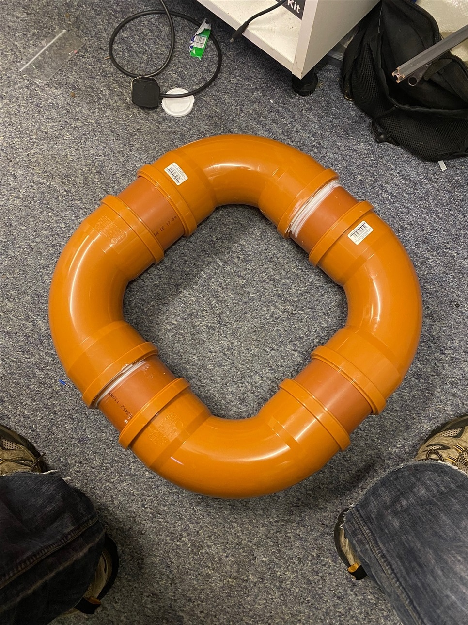
I had made a video of me starting to assemble this, whcih is fine until you get to the part where 92.5 degrees becomes a problem. So after lots of red faced pipe wrestling, reseating of gaskets and to be honest, brute force, I have my floating platform. Given this was also the source of first blood on the project, it felt only appropriate to christen my creation, Floaty McTest Face was born.
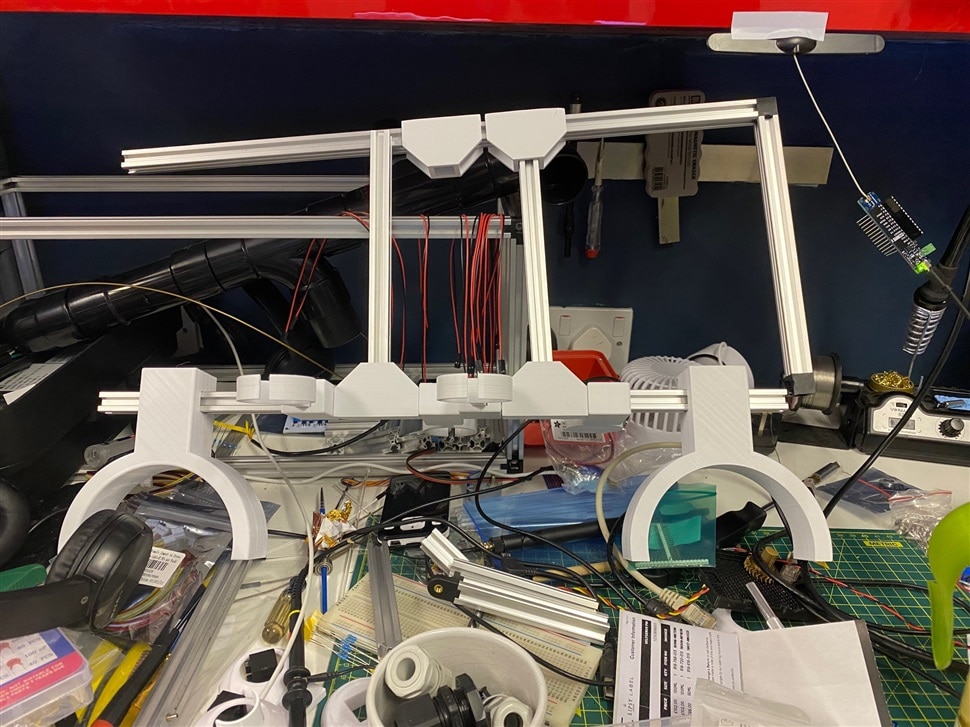
I have designed and 3d printed brackets and supports to add a assembly frame mounted on the floating platform. This uses 1515 alu profiles, 90 degree corner joints and then some fixtures and fittings of my own creation. STLs and the design files will be loaded into the github and shared. Printed in ABS and a very snug fit, with tiny tiny tiny tolerances, this was the source of second blood being drawn, which serves to only reaffirm prior to the main launch, a naming was indeed appropriate. (I am a simple man and easily amused, however the end of a 1514 alu profile with force across the side of your hand does indeed leave a bit of a mess and likely scar, this shall be known as E14 Ham from hereon in)
ON the central two vertical profiles I will be mounting the Hammond Enclosure, using the through the frame mounting holes accessed with the enclosure lid off, these will be secured into the 1515 alu profile by 4 short bolts into friction slides (and will not move once installed).
To the front of the assembly and again for the rear of the assembly we shall have
- pH probe
- Water temp sensors 1 & 2
- TDS probe
- Turbidity probe
I have designed in a replaceable mount (clip and lock) to enable to me to later add a ORP probe as well, once I can find some in stock / reasonably priced).
The side of the 1515 alu frame will also house my weather shield which containts the light level sensor and a BME280. So this means I have tested all that I intended to test in the pond and have the ability to add more as I go)
Software and Device Build
Software so Far
Its not the most elegant, but it works :)
//Libraries

#include <SPI.h>
#include <LoRa.h>
#include <Wire.h>
#include <Adafruit_Sensor.h>
#include <Adafruit_BME280.h>
#include "DHT.h"
#include <DHT_U.h>
#include <math.h>
#include <OneWire.h>
#include <DallasTemperature.h>
#include <DFRobot_B_LUX_V30B.h>

//Constants

//LUX meter
DFRobot_B_LUX_V30B    myLux(13,5,6);

//pH Sensor
#define pHSensorPin 0
#define VREF 5.0
#define SCOUNT 30

//Turbidity Sensor
#define TurbSensorPin A1

//TDS Sensor
#define TdsSensorPin 3

//DHT22 pin and object name
DHT dht(2, DHT22);    // Initialize DHT
//#define DHTPIN 2
//#define DHTTYPE    DHT22     // DHT 22 (AM2302)


//One Wire Bus (temp sensors - water)
#define ONE_WIRE_BUS 0

//Variables

int counter = 0;

// one wire
// Setup a oneWire instance to communicate with any OneWire device
OneWire oneWire(ONE_WIRE_BUS);
// Pass oneWire reference to DallasTemperature library
DallasTemperature sensors(&oneWire);

int deviceCount = 0;
float tempCu;
float tempCl;

//TDS Meter
int analogBuffer[SCOUNT];    // store the analog value in the array, read from ADC
int analogBufferTemp[SCOUNT];
int analogBufferIndex = 0,copyIndex = 0;
float averageVoltage = 0,tdsValue = 0,temperature = tempCl;

//pH sensor
unsigned long int avgValue;  //Store the average value of the sensor feedback
float phValue=(((phValue=(float)avgValue*5.0/1024/6)*3.5));
float b;
int buf[10],temp;

//BME280
Adafruit_BME280 bme;

//dht22
int chk;
float enc_humidity;  //Stores humidity value
float enc_temp; //Stores temperature value

//lightiness (open enclosure)
float lightsensor; //Resistance of grove light sensor (v1.2) in K

//turbidity
int sensorValue = analogRead(TurbSensorPin);
float turbidity = sensorValue * (5.0 / 1024.0);

///////////////////////////////////ends/////////////////////////////////

void setup() {
  Serial.begin(9600);
  sensors.begin();
  sensors.setResolution(9);
  dht.begin();
  myLux.begin();

  if (!bme.begin(0x76)) {
    Serial.println("Could not find a valid BME280 sensor, check wiring!");
    while (1);
  }

  LoRa.begin(868E6);
}

void loop() {
  int sensorValue = analogRead(TurbSensorPin);
  float turbidity = sensorValue * (5.0 / 1024.0);
  gettds();
  getph();
  getlight();
  gettemp();
  Serial.print(bme.readTemperature());
  Serial.print(",");
  Serial.print(bme.readPressure() / 100.0F);
  Serial.print(",");
  Serial.print(bme.readHumidity());
  Serial.print(",");
  Serial.print(tdsValue);
  Serial.print(",");
  Serial.print(phValue);
  Serial.print(",");
  Serial.print(dht.readHumidity());
  Serial.print(",");
  Serial.print(dht.readTemperature());
  Serial.print(",");
  Serial.print(lightsensor,DEC);
  Serial.print(",");
  Serial.print(sensors.getTempCByIndex(0));
  Serial.print(",");
  Serial.print(sensors.getTempCByIndex(1));
  Serial.print(",");
  Serial.print(turbidity);
  Serial.print(",");
  Serial.print(myLux.lightStrengthLux());
  Serial.print(",");
  Serial.print("Sending packet: ");
  Serial.println(counter);
  LoRa.beginPacket();
  LoRa.print(bme.readTemperature());
  LoRa.print(",");
  LoRa.print(bme.readPressure() / 100.0F);
  LoRa.print(",");
  LoRa.print(bme.readHumidity());
  LoRa.print(",");
  LoRa.print(tdsValue);
  LoRa.print(",");
  LoRa.print(phValue);
  LoRa.print(",");
  LoRa.print(dht.readHumidity());
  LoRa.print(",");
  LoRa.print(dht.readTemperature());
  LoRa.print(",");
  LoRa.print(lightsensor,DEC);
  LoRa.print(",");
  LoRa.print(sensors.getTempCByIndex(0));
  LoRa.print(",");
  LoRa.print(sensors.getTempCByIndex(1));
  LoRa.print(",");
  LoRa.print(turbidity);
  LoRa.print(",");
  LoRa.print(myLux.lightStrengthLux());
  LoRa.print(","); //included at end of main data string as RSSI is added last
  LoRa.endPacket();

  counter++;
  delay(30000);
}

/////////////////////////////////////////////////
////////Function things TDS, pH, Light///////////
/////////////////////////////////////////////////


void gettemp()
{
  // Send command to all the sensors for temperature conversion
  sensors.requestTemperatures();
  tempCl = sensors.getTempCByIndex(0);
  tempCu = sensors.getTempCByIndex(1);
}

void gettds()
{
   static unsigned long analogSampleTimepoint = millis();
   if(millis()-analogSampleTimepoint > 40U)     //every 40 milliseconds,read the analog value from the ADC
   {
     analogSampleTimepoint = millis();
     analogBuffer[analogBufferIndex] = analogRead(TdsSensorPin);    //read the analog value and store into the buffer
     analogBufferIndex++;
     if(analogBufferIndex == SCOUNT)
         analogBufferIndex = 0;
   }
   static unsigned long printTimepoint = millis();
   if(millis()-printTimepoint > 800U)
   {
      printTimepoint = millis();
      for(copyIndex=0;copyIndex<SCOUNT;copyIndex++)
        analogBufferTemp[copyIndex]= analogBuffer[copyIndex];
      averageVoltage = getMedianNum(analogBufferTemp,SCOUNT) * (float)VREF / 1024.0; // read the analog value more stable by the median filtering algorithm, and convert to voltage value
      float compensationCoefficient=1.0+0.02*(temperature-25.0);    //temperature compensation formula: fFinalResult(25^C) = fFinalResult(current)/(1.0+0.02*(fTP-25.0));
      float compensationVolatge=averageVoltage/compensationCoefficient;  //temperature compensation
      tdsValue=(133.42*compensationVolatge*compensationVolatge*compensationVolatge - 255.86*compensationVolatge*compensationVolatge + 857.39*compensationVolatge)*0.5; //convert voltage value to tds value
   }
}
int getMedianNum(int bArray[], int iFilterLen)
{
      int bTab[iFilterLen];
      for (byte i = 0; i<iFilterLen; i++)
      bTab[i] = bArray[i];
      int i, j, bTemp;
      for (j = 0; j < iFilterLen - 1; j++)
      {
      for (i = 0; i < iFilterLen - j - 1; i++)
          {
        if (bTab[i] > bTab[i + 1])
            {
        bTemp = bTab[i];
            bTab[i] = bTab[i + 1];
        bTab[i + 1] = bTemp;
         }
      }
      }
      if ((iFilterLen & 1) > 0)
    bTemp = bTab[(iFilterLen - 1) / 2];
      else
    bTemp = (bTab[iFilterLen / 2] + bTab[iFilterLen / 2 - 1]) / 2;
      return bTemp;
}

void getph()
{
  for(int i=0;i<10;i++)       //Get 10 sample value from the sensor for smooth the value
  {
    buf[i]=analogRead(pHSensorPin);
    delay(10);
  }
  for(int i=0;i<9;i++)        //sort the analog from small to large
  {
    for(int j=i+1;j<10;j++)
    {
      if(buf[i]>buf[j])
      {
        temp=buf[i];
        buf[i]=buf[j];
        buf[j]=temp;
      }
    }
  }
  avgValue=0;
  for(int i=2;i<8;i++)                      //take the average value of 6 center sample
    avgValue+=buf[i];
  float phValue1=(float)avgValue*5.0/1024/6; //convert the analog into millivolt
  phValue=3.5*phValue1;                      //convert the millivolt into pH value
}

void getlight()  {
  int sensorValue = analogRead(4);
  lightsensor=(float)(1023-sensorValue)*10/sensorValue;
}
and for good measure - Suprising annoyances
I had not fully appreciated how suscuptible the 1 wire implementation was to noise, this has meant that where I added a second waterproof DS18B20*1 digital temp sensor to my design. Unable to get hold of a Adafruit sensor to match I elected to go with a Amazon order as they had stock in and were availible for delivery - caveat emptor.
Notes
*1 - despite claiming to be a geniune DS18B20 sensor, I think my amazon special is not quite the real thing. Intermittant 85C readings - this tells you that the temp conversion request has not completed, -127C that the device isnt found and then spurious 100c plus readings doesnt make for very useful data. To make this more troublesome it also interfers with the outstanding Adafruit high temp DS18B20 waterproof sensor. Of all the things that have taken me down a rabbit hole, I did not expect it to be this of all things.
*2 - form over function. Where I wanted to add in the ability to measure the light level (based on another design change specifically relating to the placement of my sensor platform) i found what looked to be the PERFECT solution. Housed in a clear dome, the ambient light level sensor would give me a lux reading.
- Evening: 0.001-0.02lx;
- Moonlit night: 0.02-0.3lx;
- Cloudy indoor: 5-50lx;
- Cloudy outdoor: 50-500lx;
- Sunny indoor: 100-1000lx;
- Under summer noon light: about 10*6 lx;
- Illumination when reading books: 50-60lx;
- Home video standard illumination: 1400lx
I wanted to add this so in addition to understanding from note 1 above, the water temp at near surface and then at c40-50cm depth, the ammount of light reaching the surface of the pond. The I2C sensor should just be able to be connected up on the I2C bus along with the BME280 and no troubles ... or so i thought. Nestled in the ambient light sensor documentation is the note
This sensor is sealed by software IIC, and can not be used with other equipment or sensors using hardware IIC.
Now on my first read of this I took this to mean that the address of the device could not be changed (reasonable) and that in the event of an address conflict ... that would be a problem. Alas not, I wish I had seen this before going to the avenue of including this in my build, firstly for the lost time to debugging and taking the position of 99% of the time it is something I have done, a bad solder joint, i made a mistake. Alas not. Thankfully whilst my annoyance with the ambient light sensor continues and the form is greater than the function it provides.
The root of the problem looks to be how I2C has been implemented for the sensor (SEN0390) and some messy bit banging which goes on, this results in the sensor not returning data and then anything else you have connected on the bus, not returning data. Take one sensor away, all is happy.
The Solution: (1) keep the sensor off the I2C bus (2) SDA/SCL define the pin input using two digital pins, as such:
DFRobot_B_LUX_V30B myLux(13,5,6);//The sensor chip is set to 13 pins, SCL and SDA adopt default configuration
Why you need to include pin 13 in there is beyond me, if you dont, it wont work, if you do, it does. Also worth checking your own pin numbering on your device. I am using the Arduino Connector which is a breakoout for the grove sensors and needed me to swap pins 6 / 5 definition around for SCL and SDA.
Useful i2c scanner
// --------------------------------------
// i2c_scanner
//
// Modified from https://playground.arduino.cc/Main/I2cScanner/
// --------------------------------------

#include <Wire.h>

// Set I2C bus to use: Wire, Wire1, etc.
#define WIRE Wire

void setup() {
  WIRE.begin();

  Serial.begin(9600);
  while (!Serial)
     delay(10);
  Serial.println("\nI2C Scanner");
}


void loop() {
  byte error, address;
  int nDevices;

  Serial.println("Scanning...");

  nDevices = 0;
  for(address = 1; address < 127; address++ )
  {
    // The i2c_scanner uses the return value of
    // the Write.endTransmisstion to see if
    // a device did acknowledge to the address.
    WIRE.beginTransmission(address);
    error = WIRE.endTransmission();

    if (error == 0)
    {
      Serial.print("I2C device found at address 0x");
      if (address<16)
        Serial.print("0");
      Serial.print(address,HEX);
      Serial.println("  !");

      nDevices++;
    }
    else if (error==4)
    {
      Serial.print("Unknown error at address 0x");
      if (address<16)
        Serial.print("0");
      Serial.println(address,HEX);
    }
  }
  if (nDevices == 0)
    Serial.println("No I2C devices found\n");
  else
    Serial.println("done\n");

  delay(5000);           // wait 5 seconds for next scan
}
which when used identifies:
13:54:52.173 ->
13:54:57.095 -> Scanning...
13:54:57.142 -> I2C device found at address 0x4A ! <-- ambient light sensor (but be damned if you can actually use the device address)
13:54:57.142 -> I2C device found at address 0x76 ! <--- this one we know if the BME280, as 0x76 is the default address and you can modify to 0x77 but changing the PCB jumper connection
13:54:57.188 -> done
13:54:57.188 ->
Bonus almost there video
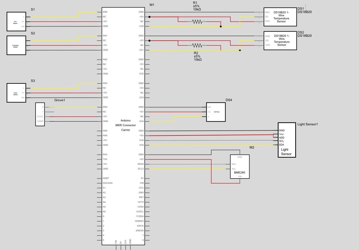
Wiring Diagram
Please find below the wiring diagram for my setup. The base module to which all components are connected is the Arduino MKR Connection Carrier, this has the MKR1300 installed on top, you do not need to worry about any additional connections, level shifting or supply voltage as this is all taken care of on the MKR Connection Carrier board (so many bonuses with using this) and it has a great price point, I paid £14-00 for mine.
This is completely compatible with the Grove connector system and modules. One point to note is to check the connection lines for your modules and the carrier board as some are NC - not connected.
You bring power into your system by providing 5.5v to the MKR Connection Carrier board. I achieved this with a low cost DC step down buck, in my case it takes the 12v supplied into the enclosure down to 5.5v DV. Importantly this is a stable and clean 5.5v.
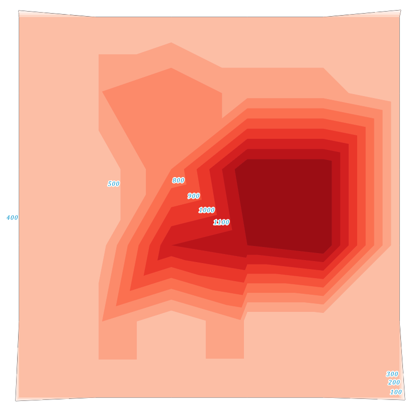
Whats getting measured?
It occurs to me that I had not added a great deal of context for my garden pond. The below is a depth diagram, sounding if you will, which i produced from my original dig measurements, depth is in mm.
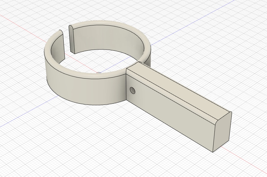
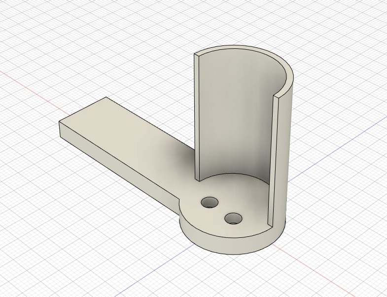
40mm holder - used to hold the 150mm long 40mm ID pipe which has a piece of insulation lagging and then the test instrument nestled inside
1515 aluminium slide profile - used to mount the 40mm holder for test equipment on the alu rail - snug fit.
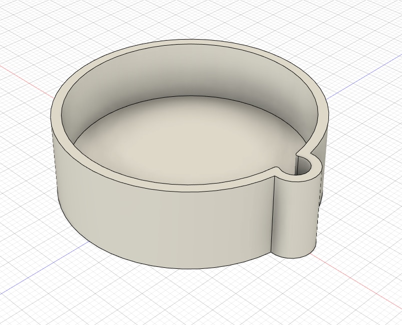
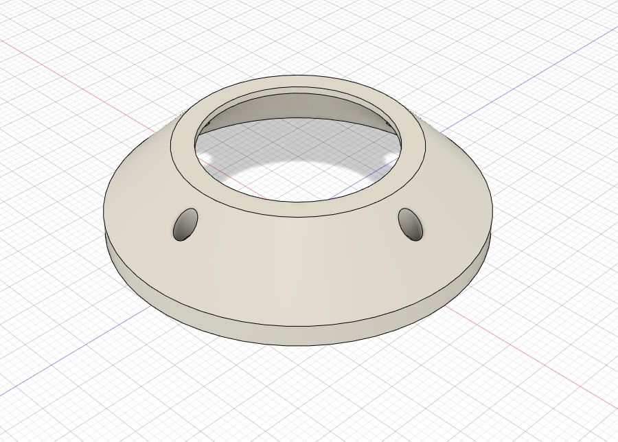
40mm ID cap - used to seal the equipment holder pipe and route cable.
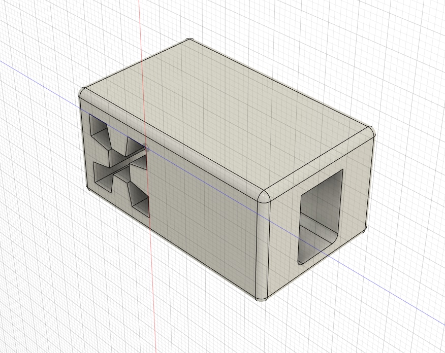
T-Junction - joins the horizonal and vertically aligned 1515 alu profile. Horizonal slides through completely, vertical wedges in place.

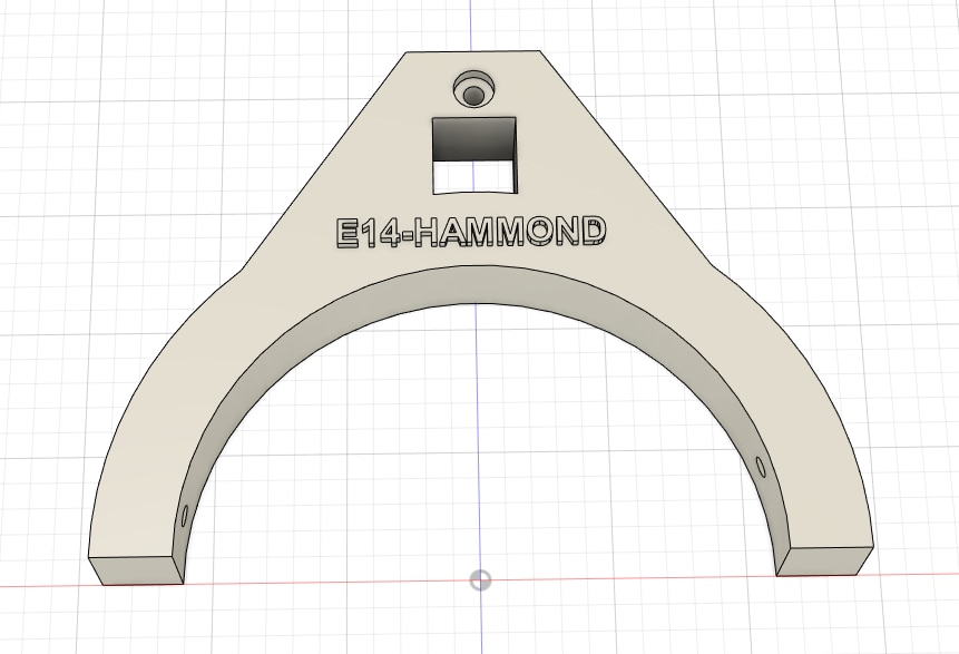
Base Bracket - connects the test assembly to the floating 110OD pipe. 1515 alu slides through
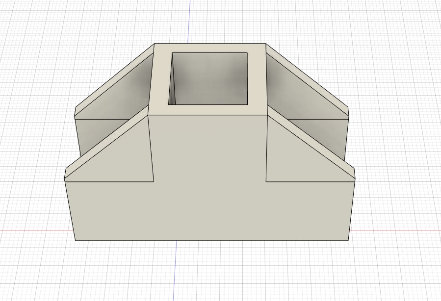
Weather base holder - 1 of these for your BME and amient light levels. The weather shieds stack on top, cables route through the bottom - drip loop 
Weather shield - I used 7 of these, secuted with 3mm rod and hot glue.
Cable stay and rescue bracket - mounted on the open sides of the pontoon and will be fitted with 6mm twisted wire run to keep my Floaty McTest Face device in approximately the same location in the pond
A zip with all the design files (autodesk fusion 360). Just in case I need to add any sort of fair use licences
Attribution-ShareAlike 4.0 International (CC BY-SA 4.0)
Top Comments