![]() BLOG#3 Implementation (Case Enclosure Reliability Monitor)
BLOG#3 Implementation (Case Enclosure Reliability Monitor)
This blog will include the implementation of the Basic Design described in the previous blog in this Series.
This Basic Design will be used as the framework implement test that will be described in in the next 2 blogs in this Series.
A project utilizing the provided 2 Arduino MKR WAN 1300 and 2 Enclosure Cases supplied by Hammond Manufacturing
This is my 3rd blog in a Series for the Design Challenge: Just Encase
| <<< PREVIOUS BLOG | NEXT BLOG >>> |
|---|---|
| Blog#4 Testing Part 1 (Case Enclosure Reliability Monitor) |
Table of Contents
Basic Design Test (first try)
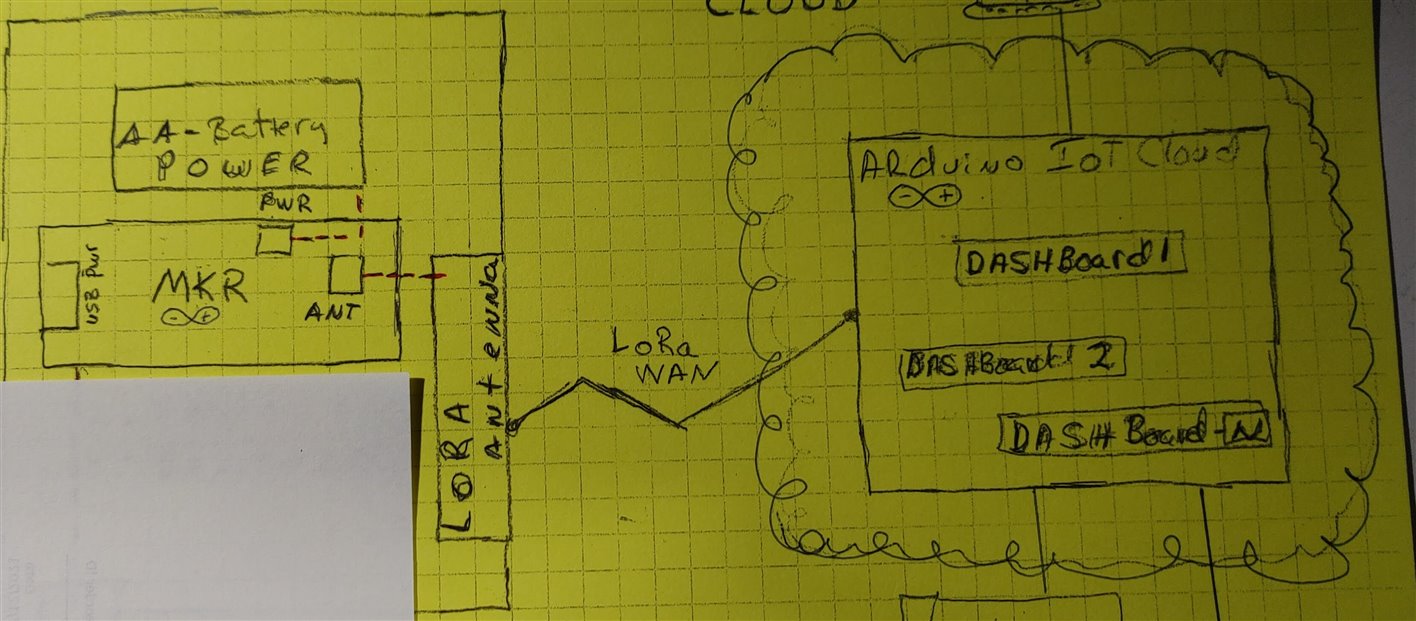
- This section will describe the Implementation of the Basic design mentioned in the first section of Blog#2
- I have included my diagram for reference
Electronics Build (First Try)
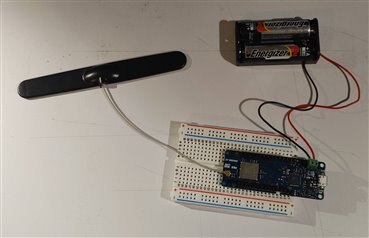
- The build involves
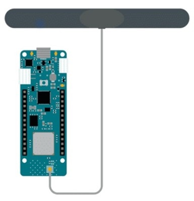
- Connecting the Lora antenna to the MKR WAN 1300
- Connecting the AA-Battery pack to the MKR WAN 1300
- Connection notes
- this will not connect to The Things Stack, Since I'm out of range
- So I had to implement a Sender/Receiver Lora connections between the 2 MKR WAN 1300's . This is described in the next next section "Electronic Build Part 2"
Software Programming (first try)
- I tried using the Arduino IoT Cloud to implement a dashboard that will track a simple counter
- Unfortunately this did not connect, because I was out of range.
- I followed the following tutorial on the Arduino documentation site
- The tutorial will be described in Appendix A
- Was this connection successful
- No, Failed on step 3 of the tutorial sections 4,5a, 5b
- section 4... Things overview, under the "Last Value / Last Update" column.
- no data
- section 5a ... TSS console on Applications > NameOfApp > End Devices. Here we can see if data is received.
- Basically, if it is not receiving any data, it means that data is not correctly passing through the gateway and the Internet to TTS.
- Section 5b ... If successful, in the "live data" section, the "first sign of life" should be a message that says "Accept join-request".
- I DID NOT see this message
- Is my location in range of a Pro Network?
- NO, The nearest LoRaWAN gateway is 5 miles from my home.
- I came up with a new design and that is described in the next sections.
Basic Design Test (New Solution)
Electronic Build (New Solution)
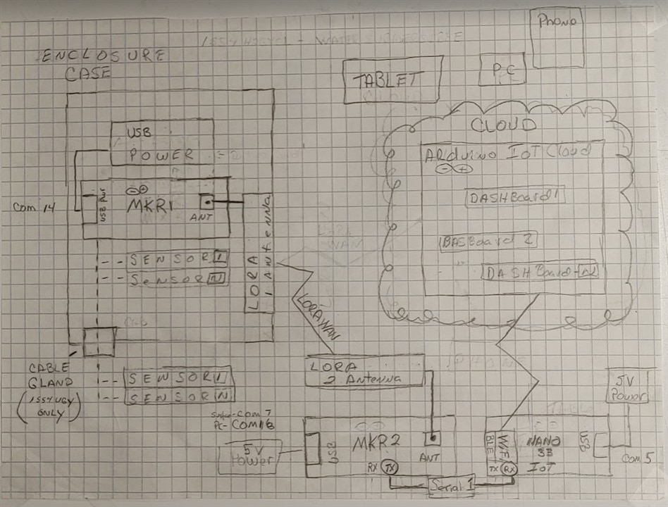
- This build will contain the NEW Design used to get the data from a MKR WAN 1300 (MKR 1) over LoRaWAN to another MKR WAN !300 (MKR 2)
- To get the Telemetry data from the MKR2 to the Nano IoT board, a serial connection is used between the MKR2 and the Nano IoT
- Then the data is sent up to the Arduino Cloud to be displayed on a dashboard
Software Programming (New Solution)
- A basic LoRa sender script will run on the MKR1 board and will be enhanced as sensors are added to the basic design.
- A counter in the script will be incremented and sent in a LoRa packet to the MKR2
- The receiver script will run on the MKR 2 board and will receive telemetry data from MKR1 over LoRaWAN.
- To get the Telemetry data (counter value) from the MKR2 to the Nano IoT board,
- The receiver script will implement serial sender code to transmit the data to the TX pin on the MKR2 board.
- On the Nano board script, Serial Receiver code will be added that will receive the Serial data on the RX pin.
- The Nano board sketch will send the data to the IoT Cloud Thing and then to the Dashboard.
- NOTE: the Nano board script is generated automatically when creating a new Thing on the Arduino IoT cloud as described in the online tutorial
I used the tutorial Send Data Using LoRa® with MKR WAN 1300 on the Arduino DOC pages.
NOTE: the scripts Failed at first run , but with the help of fellow Design Challenger christophesky Blog 5 - Getting started with the MKR 1300 (and LoRa Sender Starting LoRa failed!) Blog: i was able to get it working
Basically you need to downgrade the version of the library MKRWAN to version 1.0.15 and run the MKRWAN example script MKRWANFWUpdate_Standalone.ino
Three MCU"s, Three Sketches to get the the data through.
- The next three section will describe the 3 sketches used to get the data thru and onto the Arduino IoT cloud.
- Since I'm not near a LoRa WAN gateway, my solution involves 3 Arduino boards with 3 different sketches to do the job of getting the telemetry data to the Arduino IoT cloud.
LoRA Sender on MKR1
- This Sketch, will be used to transmit LoRaWAN packets.
- As I add sensors to the MKR 1, I plan to add code to this sketch that will add telemetry data to a packet and transmit to the LoRa Receiver Sketch, described in the next section.
- Here is an example sketch of sending LoRaWAN packets:
- MKR_LoRa_Sender_unitTest.ino
/*MKR_LoRa_SENDER
The sender will have a counter that increases each time the loop has run, and a delay of 5 seconds.
Each time the loop runs, we will send a "packet" containing the message "hello" and the number of the counter variable.
This is to ensure that we receive messages continuously.
*/

// MKRWAN - Version: 1.0.15
#include <MKRWAN.h>


#include <SPI.h>
#include <LoRa.h>

int counter = 0;
void setup() {
Serial.begin(9600);
while (!Serial);

Serial.println("LoRa Sender");

if (!LoRa.begin(915E6)) {
Serial.println("Starting LoRa failed!");
while (1);
}
}

void loop() {
Serial.print("Sending packet: ");
Serial.println(counter);

// send packet
LoRa.beginPacket();
LoRa.print("hello ");
LoRa.print(counter);
LoRa.endPacket();

counter++;

delay(5000);


LoRa Receiver on MKR2
This Sketch, will be used to receive LoRaWAN packets.
The packets will contain telemetry data that will be sent over a serial line to the Nano 33 IoT.
Here is the sketch of sending LoRaWAN packets:

MKR_LoRa_Receiver_unitTest.ino

/*
MKR_LoRa_Receiver
we will not be creating any packets. Instead, we will listen to incoming ones.
*/
// MKRWAN - Version: 1.0.15
#include <MKRWAN.h>

#include <SPI.h>
#include <LoRa.h>

String inputString = ""; // a String to hold incoming data

void setup() {
Serial.begin(9600);
Serial1.begin(9600);
while (!Serial);

Serial.println("LoRa Receiver");

if (!LoRa.begin((915E6))) {
Serial.println("Starting LoRa failed!");
while (1);
}

// reserve 200 bytes for the inputString:
inputString.reserve(200);
}

void loop() {
// try to parse packet
int packetSize = LoRa.parsePacket();
if (packetSize) {
// received a packet
Serial.print("Received packet '");

// read packet
while (LoRa.available()) {
//Serial.print((char)LoRa.read());
// get the new byte:
char inChar = (char)LoRa.read();
// add it to the inputString:
inputString += inChar;
}

Serial.println(inputString);
Serial1.print(inputString);
Serial1.print('\n');
// print RSSI of packet
Serial.print("' with RSSI ");
Serial.println(LoRa.packetRssi());
inputString = "";
}
}


Sending Data to the Arduino IoT Cloud
This sketch sends data to the IoT Cloud Dashboard.
It runs on the Nano 33 IoT board and connects via a WiFi connection.
The sketch, is Auto Generated when you initially create a thing connected to a device on the Arduino IoT cloud
NOTE: the Nano board script is generated automatically when creating a new Thing on the Arduino IoT cloud as described in the online tutorial
Getting started with the Arduino IoT Cloud
Here is the sketch generated to send data to the thing that I created on the IoT cloud
Counter_dec30a.ino

/*
Sketch generated by the Arduino IoT Cloud Thing "Counter"
https://create.arduino.cc/cloud/things/8365259b-0af3-440e-add6-fc53e82ea22d

Arduino IoT Cloud Variables description

The following variables are automatically generated and updated when changes are made to the Thing

String counter;
int int_Counter;

Variables which are marked as READ/WRITE in the Cloud Thing will also have functions
which are called when their values are changed from the Dashboard.
These functions are generated with the Thing and added at the end of this sketch.
*/

#include "thingProperties.h"
String inputString = ""; // a String to hold incoming data
bool stringComplete = false; // whether the string is complete

void setup() {
// Initialize serial and wait for port to open:
Serial.begin(9600);
Serial1.begin(9600);

while (!Serial) {
; // wait for serial port to connect. Needed for native USB port only
}

// Defined in thingProperties.h
initProperties();

// Connect to Arduino IoT Cloud
ArduinoCloud.begin(ArduinoIoTPreferredConnection);

/*
The following function allows you to obtain more information
related to the state of network and IoT Cloud connection and errors
the higher number the more granular information you’ll get.
The default is 0 (only errors).
Maximum is 4
*/
setDebugMessageLevel(2);
ArduinoCloud.printDebugInfo();
}

void loop() {
ArduinoCloud.update();
// Your code here

// use the string when a newline arrives:
if (stringComplete) {
Serial.println(inputString);

//USE THE InputString HERE
counter = inputString;
int_Counter++;
//ArduinoCloud.update();
// clear the string:
inputString = "";
stringComplete = false;
}

//At the very end of the loop check for serial data
serialEvent();
}

/*
Since Counter is READ_WRITE variable, onCounterChange() is
executed every time a new value is received from IoT Cloud.
*/
void onCounterChange() {
// Add your code here to act upon Counter change
}

/*
SerialEvent occurs whenever a new data comes in the hardware serial RX. This
routine is run between each time loop() runs, so using delay inside loop can
delay response. Multiple bytes of data may be available.
*/
void serialEvent() {
while (Serial1.available()) {
// get the new byte:
char inChar = (char)Serial1.read();
// add it to the inputString:

inputString += inChar;
// if the incoming character is a newline, set a flag so the main loop can
// do something about it:
if (inChar == '\n') {
stringComplete = true;
}
}
}


/*
Since IntCounter is READ_WRITE variable, onIntCounterChange() is
executed every time a new value is received from IoT Cloud.
*/
void onIntCounterChange() {
// Add your code here to act upon IntCounter change
}
Lora Receiver/Serial Sender on MKR2
- This sketch is used to RECEIVE LoRaWAN packets and SEND the data contained in the packet over the Serial1 TX pin.
- MKR_LoRa_Receiver_unitTest.ino
/*
MKR_LoRa_Receiver
we will not be creating any packets. Instead, we will listen to incoming ones.
1-20-2020 Added OLED Adafruit_SSD1306 support.

*/
// MKRWAN - Version: 1.0.15
#include <MKRWAN.h>

#include <SPI.h>
#include <LoRa.h>

// Include Adafruit Graphics & OLED libraries
#include <Adafruit_GFX.h>
#include <Adafruit_SSD1306.h>

// CODE for MKR WAN 1300
#define SCREEN_WIDTH 128 // OLED display width, in pixels
#define SCREEN_HEIGHT 32 // OLED display height, in pixels

// Declaration for an SSD1306 display connected to I2C (SDA, SCL pins)
#define OLED_RESET     4 // Reset pin # (or -1 if sharing Arduino reset pin)
Adafruit_SSD1306 display(SCREEN_WIDTH, SCREEN_HEIGHT, &Wire, OLED_RESET);

String inputString = "";         // a String to hold incoming data

void setup() {
  Serial.begin(9600);
  Serial1.begin(9600);
  while (!Serial);

  Serial.println("LoRa Receiver");

  if (!LoRa.begin((915E6))) {
    Serial.println("Starting LoRa failed!");
    while (1);
  }

  // reserve 200 bytes for the inputString:
  inputString.reserve(200);

  //OLED CODE
  // Start Wire library for I2C
  Wire.begin();
  // initialize OLED with I2C addr 0x3C
  display.begin(SSD1306_SWITCHCAPVCC, 0x3C);

}

// OLED DISPLAY FUNCTION to display numbers.
void displayValues(String v){
  // Delay to allow sensor to stabalize
  delay(2000);
  // Clear the display
  display.clearDisplay();
  //Set the color - always use white despite actual display color
  display.setTextColor(WHITE);
  //Set the font size
  display.setTextSize(1);
  //Set the cursor coordinates
  display.setCursor(25,0);
  display.print("Rcvd Packet");
  display.setCursor(33,12);
  display.setTextSize(3);
  display.print(v);
}

void loop() {
  // try to parse packet
  int packetSize = LoRa.parsePacket();
  if (packetSize) {
    // received a packet
    Serial.print("Received packet '");

    // read packet
    while (LoRa.available()) {
      //Serial.print((char)LoRa.read());
      // get the new byte:
      char inChar = (char)LoRa.read();
      // add it to the inputString:
      inputString += inChar;
    }

    // display on OLED
    displayValues(inputString);
    display.display();

    Serial.print(inputString);
    Serial1.print(inputString);
    Serial1.print('\n');
    // print RSSI of packet
    Serial.print("' with RSSI ");
    Serial.print(LoRa.packetRssi());
    Serial.println("");
    inputString = "";
  }
}
.
Serial Receiver/IoT Cloud Sender on the NANO 33 IoT
- This sketch RECEIVES data over Serial1 with the jumper attached to the RX pin.
- The function SerialEvent() is called to read the data off the RX pin 1 character at a time.
- When the character received is a CR/LF, a flag is set and will indicate to the caller that Data is in the buffer inputString
- I did read , that this function is automatically called when using Serial1, but could not get it to work on the MKR? So I placed a call at the end of the loop and it seems to work?
- The function SerialEvent() is called to read the data off the RX pin 1 character at a time.
- The sketch then updates the IoT thing counter variable and UPDATES the counter thing on the IoT Cloud and the Dashboard is updated as well.
- The sketch is created when you add/edit the Thing on the IoT Cloud.
- I added the functions serialEvent() and retFloat()
- And some code in setup() and most of the code in the function loop()
- Counter_dec30a.ino
/*
  Sketch generated by the Arduino IoT Cloud Thing "Counter"
  https://create.arduino.cc/cloud/things/8365259b-0af3-440e-add6-fc53e82ea22d

  Arduino IoT Cloud Variables description

  The following variables are automatically generated and updated when changes are made to the Thing

  String counter;
  int int_Counter;

  Variables which are marked as READ/WRITE in the Cloud Thing will also have functions
  which are called when their values are changed from the Dashboard.
  These functions are generated with the Thing and added at the end of this sketch.
*/

#include "thingProperties.h"
String inputString = "";         // a String to hold incoming data
bool stringComplete = false;  // whether the string is complete


float retFloat(String stringOne) {
  // Given a tuple pair in the form varname:value ex. inTemp:1.1
  // return a float value to the right of the cloen character
//Serial.println(stringOne);
int firstClosingBracket = stringOne.indexOf(':');
String value = String(stringOne.substring(firstClosingBracket+1));
//Serial.println(value);
float Temp  = value.toFloat();
   return Temp;
}
void setup() {
  // Initialize serial and wait for port to open:
  Serial.begin(9600);
  Serial1.begin(9600);

  while (!Serial) {
    ; // wait for serial port to connect. Needed for native USB port only
  }

  // Defined in thingProperties.h
  initProperties();

  // Connect to Arduino IoT Cloud
  ArduinoCloud.begin(ArduinoIoTPreferredConnection);

  /*
     The following function allows you to obtain more information
     related to the state of network and IoT Cloud connection and errors
     the higher number the more granular information you’ll get.
     The default is 0 (only errors).
     Maximum is 4
 */
  setDebugMessageLevel(2);
  ArduinoCloud.printDebugInfo();
}

void loop() {
  ArduinoCloud.update();
  // Your code here

  // use the string when a newline arrives:
  if (stringComplete) {
    Serial.print("received on RX PIN:");
    Serial.print(inputString);


    //USE THE InputString HERE
    counter = inputString;
    int_Counter++;
    inTemp = retFloat(inputString);
    Serial.print("Sending value = ");
    Serial.println(inTemp);
    //ArduinoCloud.update();
    // clear the string:
    inputString = "";
    stringComplete = false;
  }

  //At the very end of the loop check for serial data
  serialEvent();
}

/*
  Since Counter is READ_WRITE variable, onCounterChange() is
  executed every time a new value is received from IoT Cloud.
*/
void onCounterChange()  {
  // Add your code here to act upon Counter change
}

/*
  SerialEvent occurs whenever a new data comes in the hardware serial RX. This
  routine is run between each time loop() runs, so using delay inside loop can
  delay response. Multiple bytes of data may be available.
*/
void serialEvent() {
  while (Serial1.available()) {
    // get the new byte:
    char inChar = (char)Serial1.read();
    // add it to the inputString:

    inputString += inChar;
    // if the incoming character is a newline, set a flag so the main loop can
    // do something about it:
    if (inChar == '\n') {
      stringComplete = true;
    }
  }
}


/*
  Since IntCounter is READ_WRITE variable, onIntCounterChange() is
  executed every time a new value is received from IoT Cloud.
*/
void onIntCounterChange()  {
  // Add your code here to act upon IntCounter change


}
Running the Basic Design
- This Section will describe the full implementation of the Basic Design
- Send counter data over LoRaWAN (on MKR1 )
- Receive data over LoRaWAN (on MKR2 )
- Send data over serial using TX pin
- Receive data over serial using RX pin (on Nano 33 IoT )
- Send data over WiFI connection to Arduino Iot Cloud.
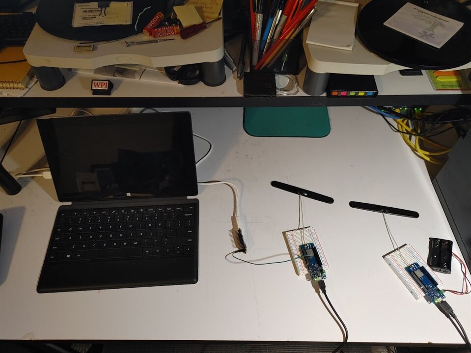
- The 3 components of my design
- MKR1 is on the right
- MKR2 is in the middle
- Nano 33 IoT is on the left
- This short video will show the Basic design running.
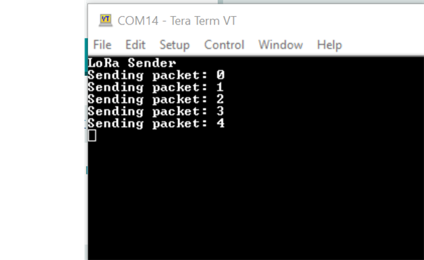
- The MKR1 is attached to the PC and the output of the sketch is shown on the Tera Term console on the right hand side on COM14
- The console shows the counter value being sent. The packet contains the string "counter:<counter value>"
- The console shows the counter value being sent. The packet contains the string "counter:<counter value>"
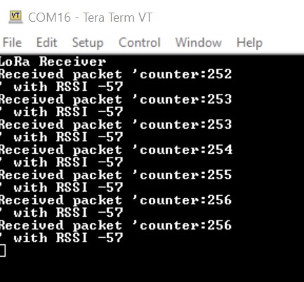
- The MKR2 is also attached to same PC for this run and the output of the sketch is shown on the Tera Term Console on COM 16
- The console show the received packet containing the string "counter<counter value>"
-
- The console show the received packet containing the string "counter<counter value>"
- The Nano 33 IoT is attached to a Microsoft Surface PC and the sketch is built in the Arduino web editor.
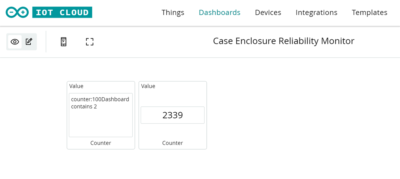
- The sketch is displayed on the Tera Term console on COM5.
- The sketch will read the serial RX pin and send the string to the Dashboard on the IoT cloud.
- The dashboard contains 2 widgets and is displayed on a webb browser displayed on the upper screen
- The first widget displays the string received and sent from the sketch running on the Nano33 IoT board, described above.
- The Second displays the value of a counter in the sketch on the Nano33 IoT.
- This proves that the Counter value from the MKR1 board makes it way throufh the design onto the Dashboard.
- this basic design will be used to experiment with sensors attached to the MKR1 board and placed in an enclosure to test
On to the next Blog
- In the next Blog, I will:
- use this basic design to add functionality
- to attach sensors to the MKR1 board
- and send that sensor telemetry data on through the basic design
- and up to the IoT cloud and the Dashboard to visualize this data.
REFERENCES
Addendum_BLOG_B_References_BLOG3
APPENDIX A - Connect your LoRaWAN® devices to the Arduino Cloud platform via The Things Network.
- This Appendix will. Describe my notes on following tutorial in the Arduino DOCS.
Goals
The goals of this project are:
- Configure a LoRaWAN® device in the Arduino Cloud.
- Register an account on The Things Console.
- Create a simple testing program for the end device.
- View data from the device in the Arduino Cloud.
- Send data to the device from the Arduino Cloud.
- Connect the antenna to the MKR WAN 1300 connector as follows:
- Configure the MKR WAN 1300
- Follow step1 in the tutorial
- Registering the Things Stack Network
- Follow Step 2 in the tutorial
- Completing Arduino Cloud Setup
- Follow Step 3 in the tutorial
- I was unable to connect directly to the LoRaWAN, because of my Location.
- I will be trying to connect by driving closer to a TSS gateway about 5 miles from my home, to see if this design works?
- In the meantime, I will add another communication layer to my design.
| <<< PREVIOUS BLOG | NEXT BLOG >>> |
|---|---|
| Blog#4 Testing Part 1 (Case Enclosure Reliability Monitor) |

Top Comments
-

skruglewicz
-
Cancel
-
Vote Up
0
Vote Down
-
-
Sign in to reply
-
More
-
Cancel
Comment-

skruglewicz
-
Cancel
-
Vote Up
0
Vote Down
-
-
Sign in to reply
-
More
-
Cancel
Children