


Orbweaver Rover - Making the rover
Orb-weaver Rover - Full Battery Test <----- Previous Blog
Table of Contents
 1. Introduction
Hi! This will be my 4th blog for the Orb-weaver project. In the last blog, I covered a 45-hour long test I did with one of the sensor boxes. In this blog, I will focus on the main part of this project, the rover itself. This is something I’ve been working on in the background since the project started pretty much and now you’ll see why. This blog will be dedicated to the mechanical design of the rover, and at the end of this blog, we will have what I will call the minimum configuration rover. Before I get to my design, let’s take a look at where I got the inspiration from.
2. Inspiration
As you might have guessed, I drew inspiration from the NASA rovers that are currently exploring Mars. There are 5 rovers sent to Mars by NASA: Sojourner, Spirit, Opportunity, Curiosity, and Perseverance. These are amazing 6 wheel robots that are literally on another planet, the thought of that still seems so unreal, but also so amazing. They are much bigger in real life than I have previously thought.
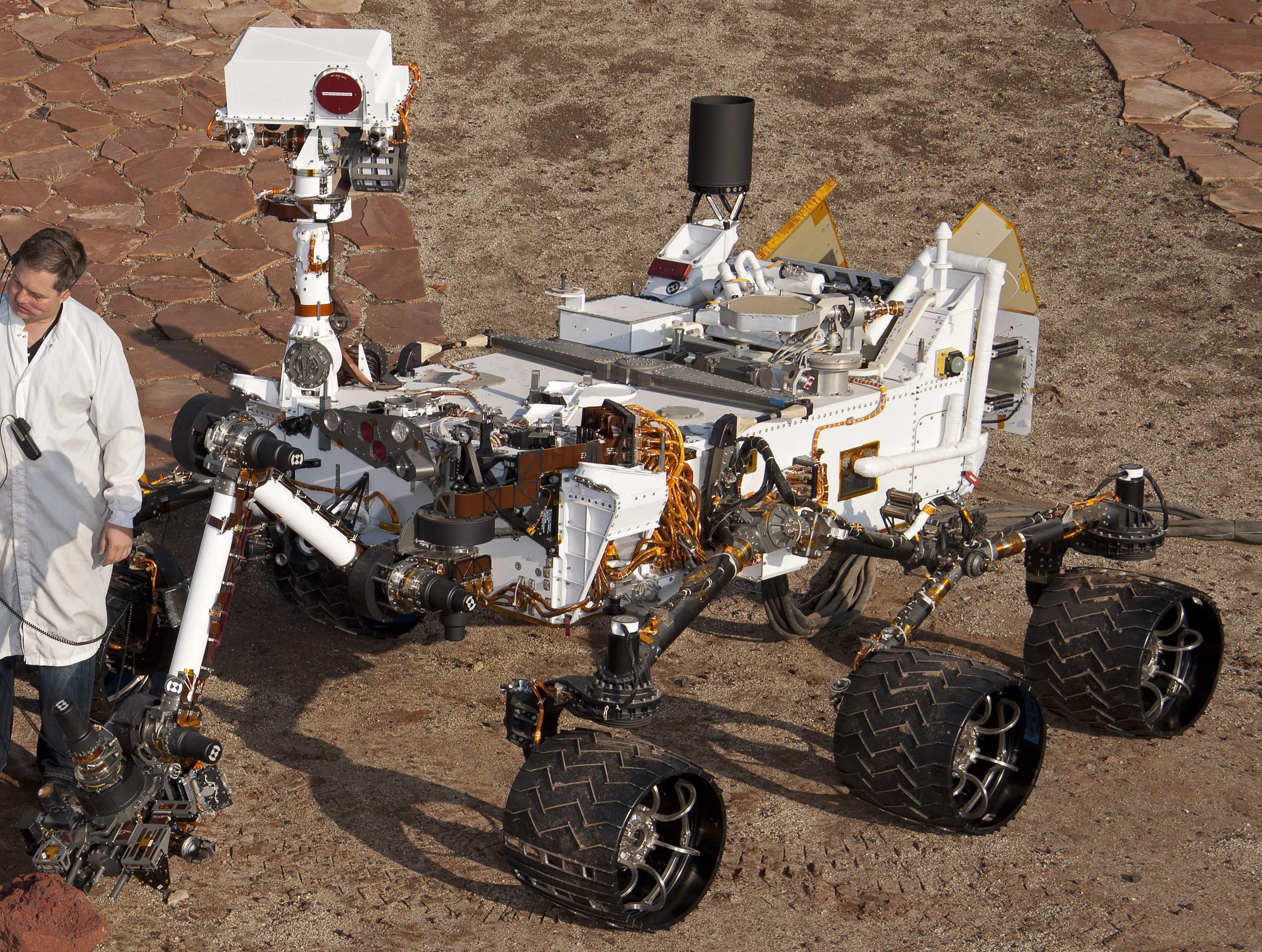
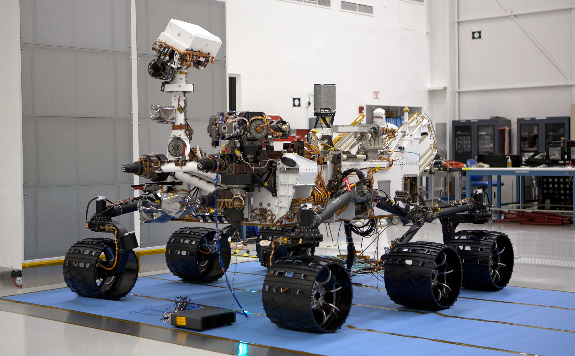
Some things I find quite interesting about the rover are the rocker-bogie suspension, the radioisotope power system (MMRTG), and a whole bunch more cool tools on the rover themselves. Another thing that I never thought about was the rover speed. The rover's top speed is about 5cm/s (2 inches). However, in order to ensure a safe drive, the rover is equipped with hazard avoidance software that causes the rover to stop and reassess its location every few seconds which brings the overall average speed down to about 1cm/s. I found a lot of cool things shared by NASA about the rover, here are a few cool links, one with an interactive 3D model!
- Interactive 3D model: https://mars.nasa.gov/msl/rover-3d/
- About Curiosity: https://mars.nasa.gov/msl/spacecraft/rover/summary/
- Rover wheels and speed: https://mars.nasa.gov/mer/mission/rover/wheels-and-legs/
- Electrical power: https://mars.nasa.gov/mars2020/spacecraft/rover/electrical-power/ & https://mars.nasa.gov/msl/spacecraft/rover/power/
3. Design
There’s a lot of information shared by NASA on their amazing rovers, but now it’s time to get to the design of my baby rover. Before I get to the design itself, let’s first look at what are some of the things I plan on integrating on the rover that we need to incorporate into the design:
- RC wheels - though I would love to make my own, I sadly can't work with TPU on my current setup
- Digilent motors that I've shown in the first blog
- MG995 servo motors
- Hammond Enclosure as the main structure and body - if this doesn't show toughness, nothing will!
With that out of the way, let’s take a look at the final design first, and then I’ll go part by part explaining the design for it!
It's just a drawing teaser, but we will get to the real thing by the end of this blog! Let's take a look at specific parts of the rover first and how they're designed.
Gearbox
The first part of the design that I will cover is the gearbox. This is the part that will connect the Digilent motor to the RC wheels I’ve shown above. The easiest thing to do would be to mount the wheel directly to the motor, but this means that the weight would be transferred directly onto the small bearings of the motor and that we would be stuck with the gearing that the motor has. Here is a video to show why that would be a bad idea for the rover:
The wheel spins way too fast for what we need, so why not reduce the speed and increase the torque along the way. In the first blog, I covered a lot of simulations and calculations for different kinds of parameters for the rover and set on the reduction ratio of 3.
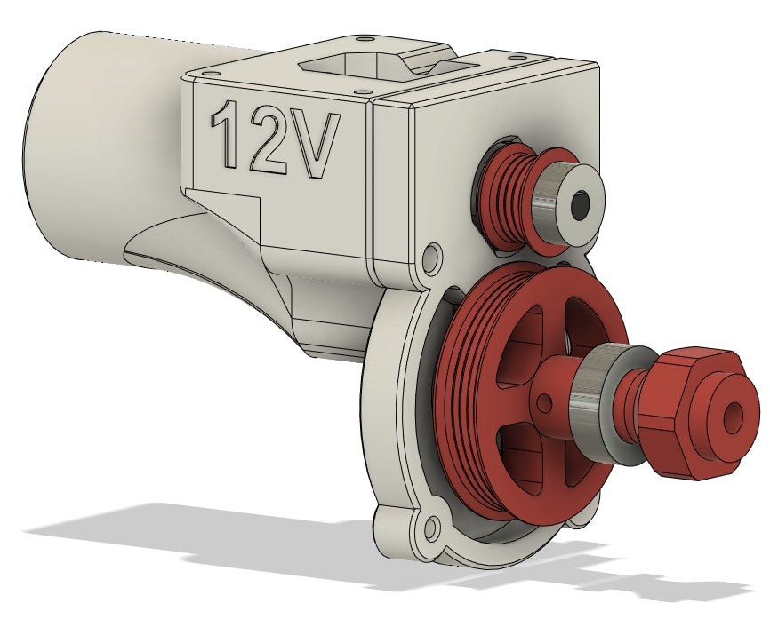
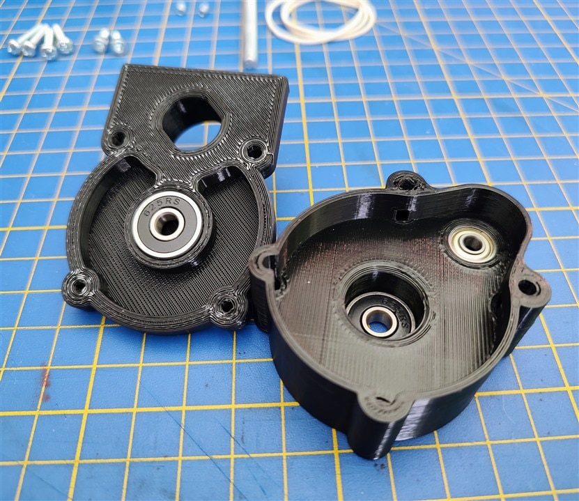
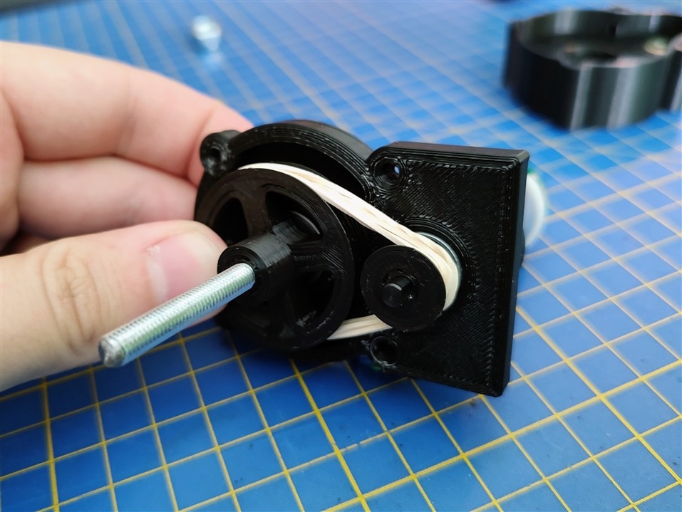
There are many different ways we can transfer torque, we can look at different gear arrangements, belts, and so on. I will cover 2 approaches here, one will be using something that can be categorized into a belt drive and a geared transfer method. I wanted to use small O-rings to transfer the torque, but the rubber was too slippery and it would sleep on the pulleys no matter how tight I got it, so I tried using a couple of common rubber bands, which proved to work wonderfully. Here are a few pictures of the design:
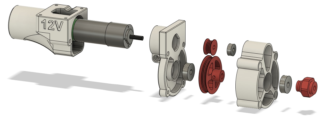
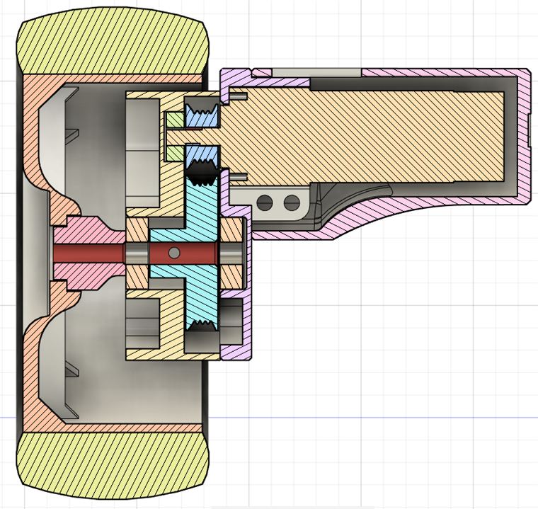
The motor is connected to a small pulley which is supported by a small 4mm bearing and it transfers torque to a bigger pulley that is mounted on 2 5mm bearings which are the ones that need to handle the weight. This way we’ve transferred the load from the small motor bearings to the much stronger 5mm bearings.
I went with this approach for now because it allows for the small pulley to slip in case the wheel gets jammed somewhere. This is important because I don’t have current sensors for the motors (I plan on getting them for a future build), so I don’t burn out the motor or the controller when it slips. I did a few tests with the rubber bands, and when I used 3 of them, I got about 1.5A on the motor when I blocked the wheel, which is acceptable both for the motor and the motor controller. I also made a geared design that fits into the same form factor as the one with the rubber bands. Here is a picture of that.
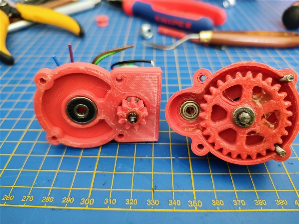
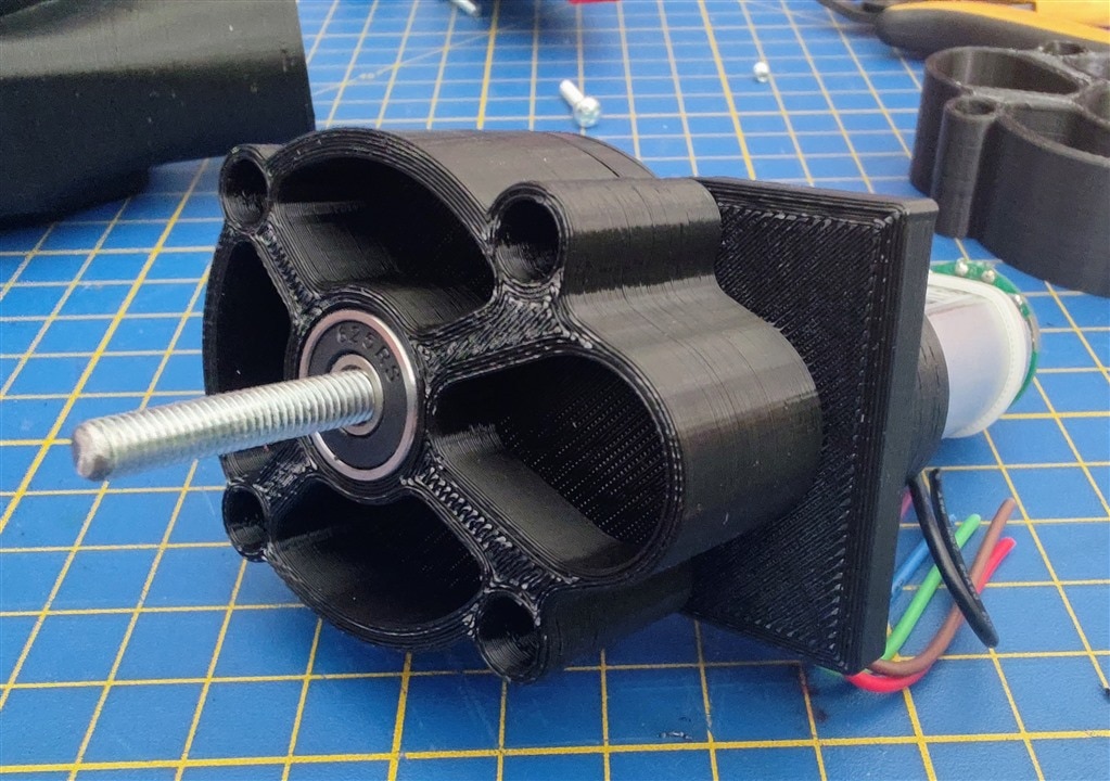
It performs surprisingly well and quietly considering I am using just 3D printed gears. But if the wheel got jammed, there would be a possibility of killing the motor or the controller which I am trying to avoid. Since I plan on working on the rover for quite some time, this is the gearbox that will in the end be on the rover because I will have much more precise wheel odometry compared to the rubber band approach.
There have been some changes on the parts shown above which you can see in the next blog. I've added a metal nut in the big pulley and the wheel hub, so the grub screws don't destroy the threads.
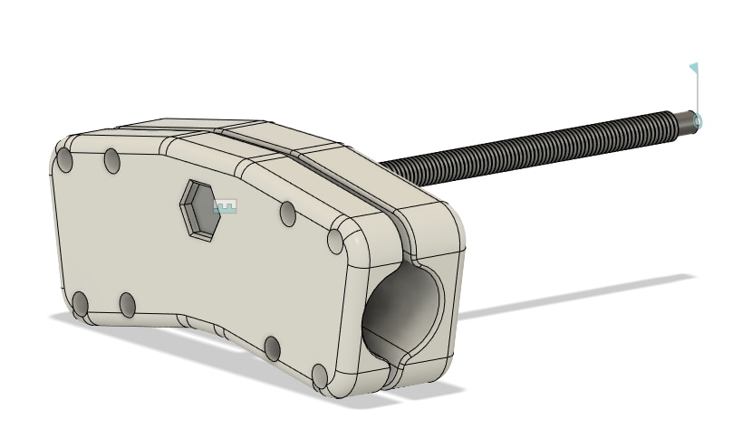
Wheel assembly
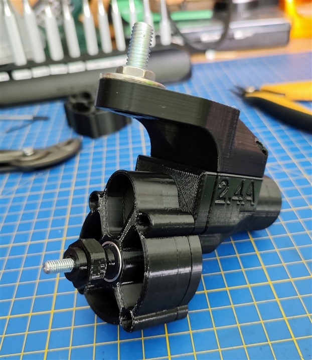
Besides having a geared DC motor, every wheel is also equipped with an MG995 servo for steering each of the wheels. The easiest thing to do here would be to mount the gearbox and wheel directly to the servo motor with an M3 screw, but that construction wouldn’t fare well under any kind of load. That’s why I redesigned it to use an M8 screw and an 8mm bearing so I can take the load off the servo completely. The servo mount also has a part that connects to a PVC pipe that goes to the rover suspension.

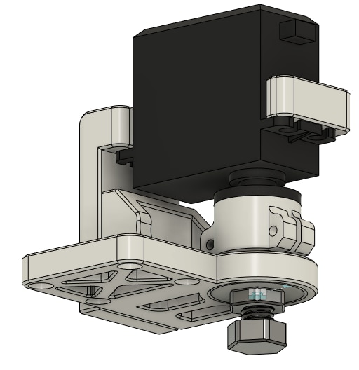
One thing I tried giving a thought to here is leaving some space in the 3D printed models for the wires to go inside the pipes rather than on the outside. This will give the rover a much cleaner look and also there will be less chance of snagging a cable somewhere when they are hidden inside the pipes.
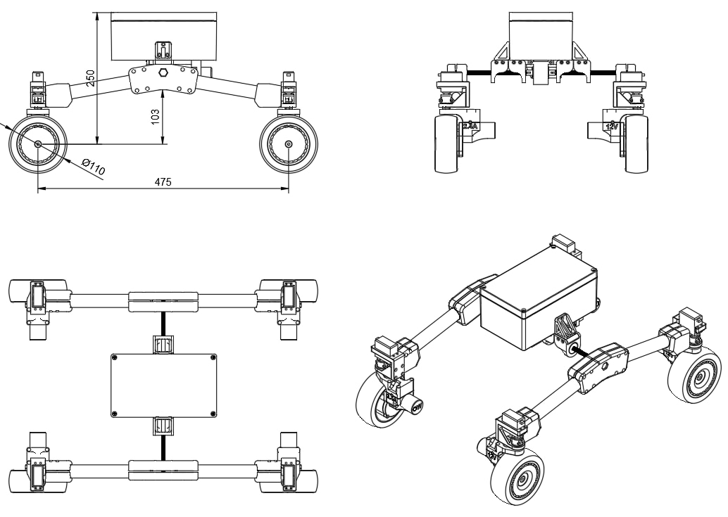
Differential suspension
Now we come to the suspension of my rover. Unlike the NASA rovers, I will have only 4 wheels instead of 6, so I can’t go and copy the rocker-bogie suspension completely, but I can take inspiration from it. Here is a link to an interactive 3D model of the rover where you can click on the suspension to get more details about it: https://mars.nasa.gov/msl/rover-3d/
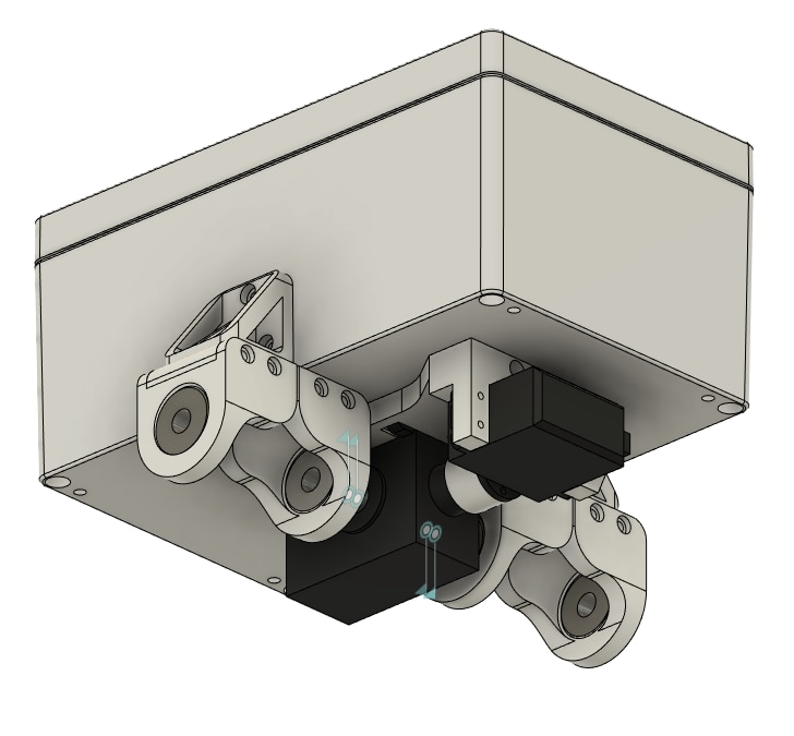
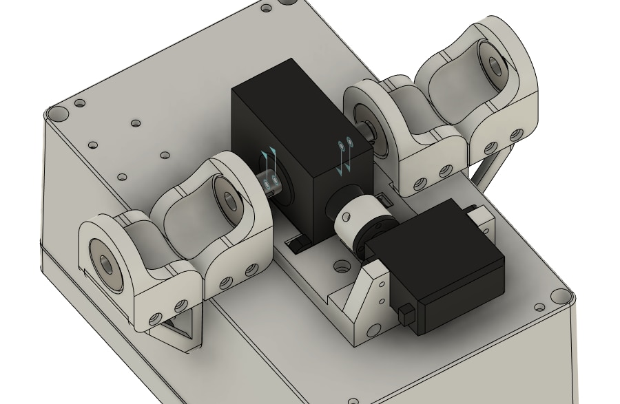
What rocker-bogie does amazingly is how it moves the body of the rover only half of what the wheels are moving, keeping all of the wheels on the surface and therefore keeping the whole rover more stable. Instead of going with the rockers, I went with a differential from an old RC car that I have. This causes the same effect as with the rockers, but it gives me the additional ability to attach a continuous servo motor to the input shaft of the differential to have active control of the rover body as you will see later in the blog. Here are some pictures of how I designed the suspension for the rover.
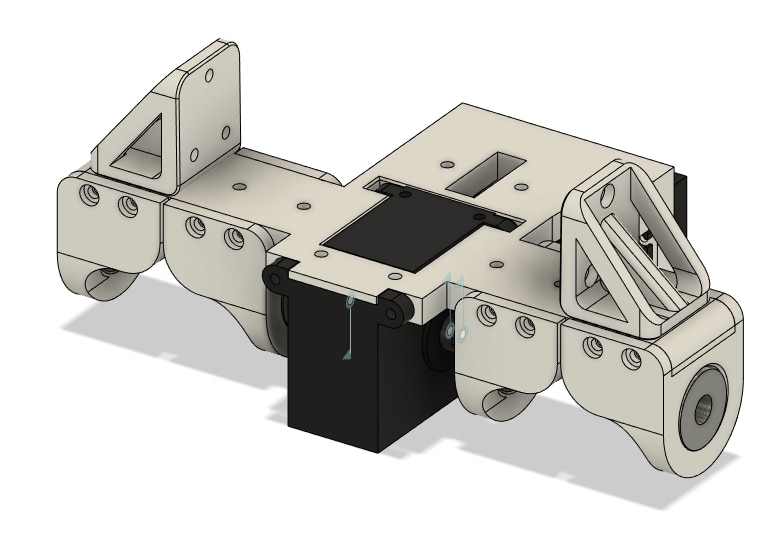
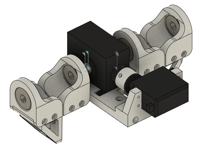
The main structural part for the suspension will be one of the Hammond enclosures that I will use as the body of the rover. The differential and bearing mount, as well as the suspension braces, will be screwed into the box to give it extra rigidity.
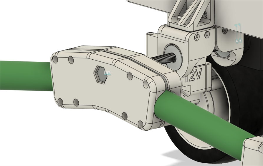
Connecting everything together
The only thing left to do is connect the wheel assemblies to the suspension and body. To connect everything together I designed 2 half pipe clamps that attach with a couple of M3 screws with a big M8 bolt that goes all the way to the differential through the suspension bearings.
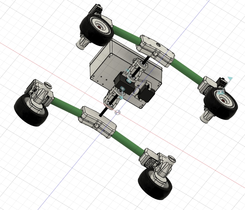
Full Assembly
With all of that done, here are a few pictures of the finished assembly as well as a video showing how everything goes together.

That would be it for the model. The design is not yet finished, there are still a few things I want to change on it, as soon as I do that, I will upload all of the files on GitHub. There are some details I didn't get to talk about at this moment, but I will cover them in the next blog where I'll be playing with the electronics and the wiring,
4. Build
After a long few weeks of designing this when I had free time, it was finally time to start building the rover. You can see from the video above how most of the parts go together. One thing to point out is that I design the holes for the screws with a smaller diameter, for example, for M3 screws, I put a 2.4mm hole, so the screw can cut its own threads when I screw it in. Here I'll cover how the gearbox should be put together as well as how I assembled the suspension part.
Gearbox
The gearbox by far has the smallest parts and requires the most time to be assembled properly. As mentioned above, I will now show the rubber band version and how to assemble it, though, the geared version follows the same process, it just needs a bit of grease to run properly. Here are the parts that will be needed for the gearbox.
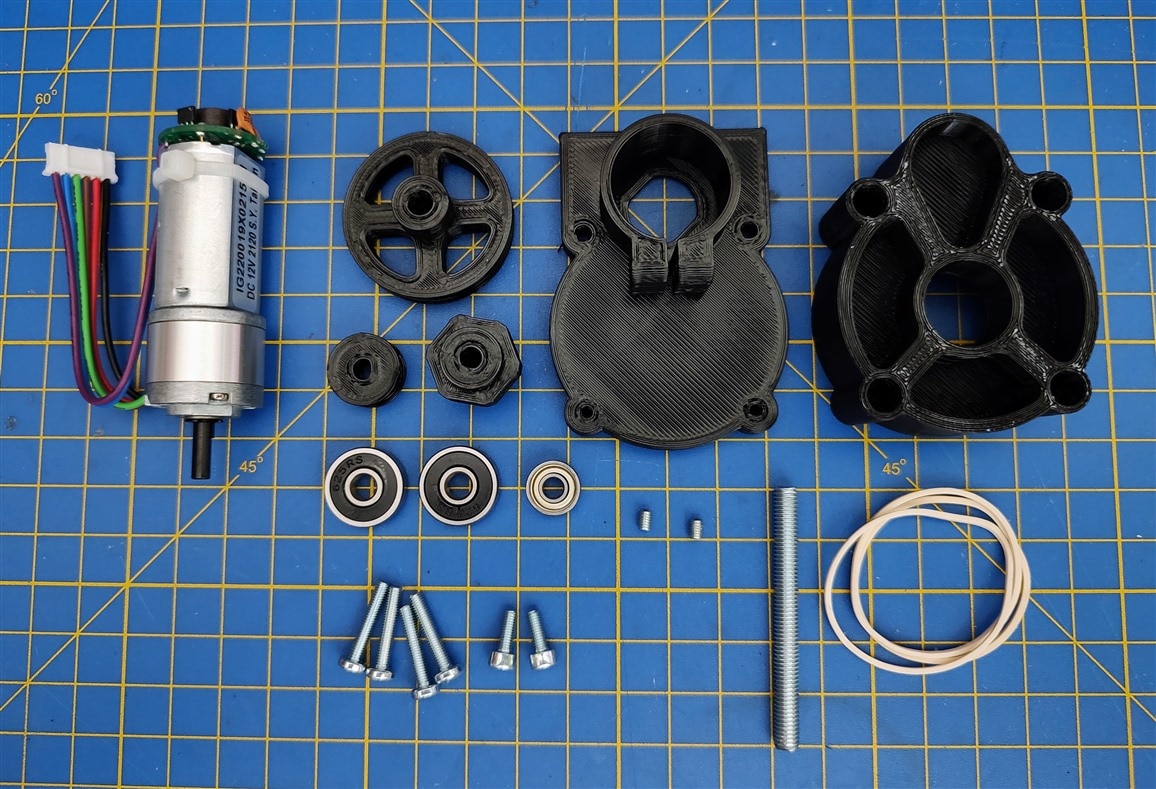
Here is the list of parts:
- Digilent motor
- Big pulley - 3D printed
- Small pulley - 3D printed
- Wheel hub - 3D printed
- Motor plate - 3D printed
- Gearbox casing - 3D printed
- 2 625RS bearings
- 694ZZ bearing
- M5 threaded rod - 50mm
- 4 M3x15mm screws
- 2 M3x8mm screws
- Rubber bands
- 2 M3 grub screws
The first step is to put the bearing into the housing and the motor plate, this is most easily done with a small vice or with a small rubber mallet as I did.
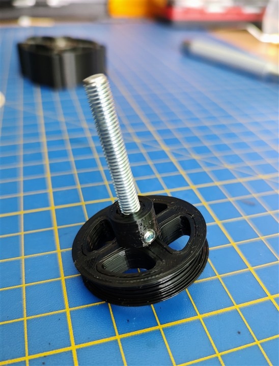
The next step is to thread the threaded rod into the big pulley and secure it with a grub screw. To thread the rod into the big pulley, I recommend using a drill on the threaded rod and holding the big pulley in the hand. You should end up with something like this.
The next step is putting the motor into the motor plate and securing it with the 2 shorter M3 screws. While we're working with the motor we can also put on the small pulley which press fits on the shaft. I put it on the motor with the help of a small rubber mallet.
The next step is putting the rubber bands on the pulleys. Since they are stretched, you will have to hold the big pulley with one finger. As mentioned above, I used a total of 3 rubber bands, since I got about a 1.5A draw with that setup.
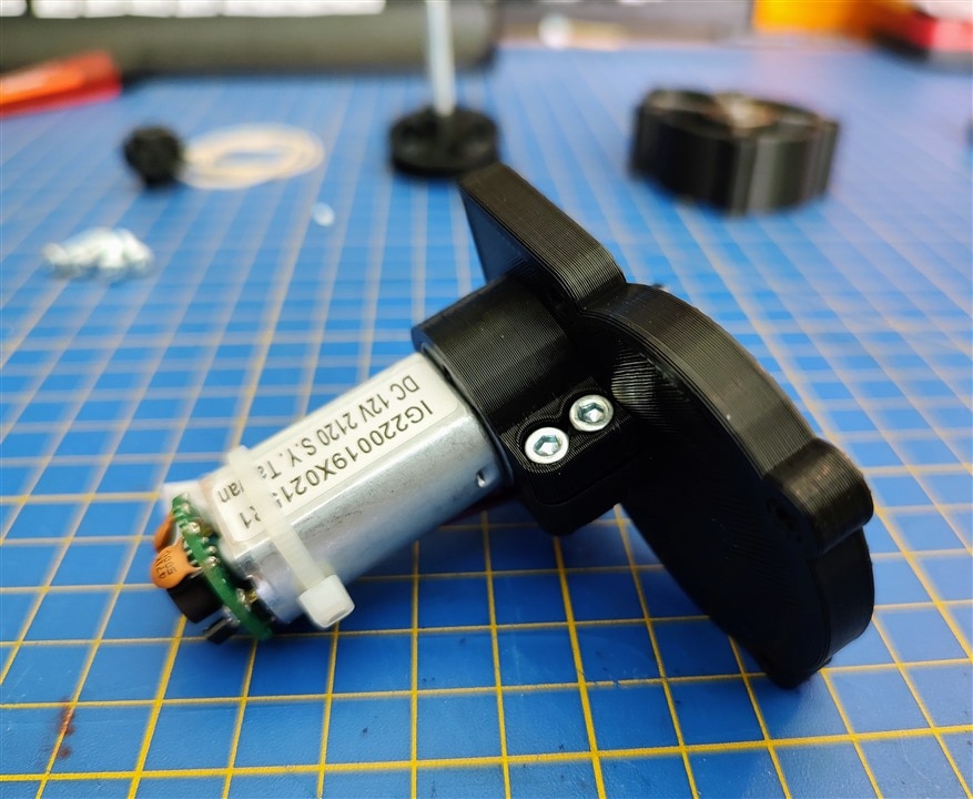
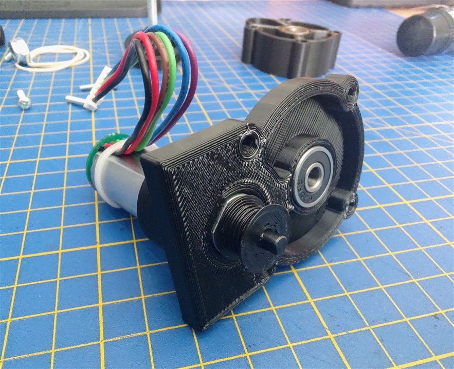
While holding the big pulley, now you need to put on the gearbox casing. This can be a little fiddly to get the motor shaft in the 4mm bearing, But as soon as you get that, it will all click in place and you should have something that looks like this.
The only thing left to do is to attach the gearbox now to the motor casing and the rest of the wheel assembly which is done with the 2 top screws on the gearbox casing (the 2 on the right on the picture above), and here is how that looks in the end.
Suspension
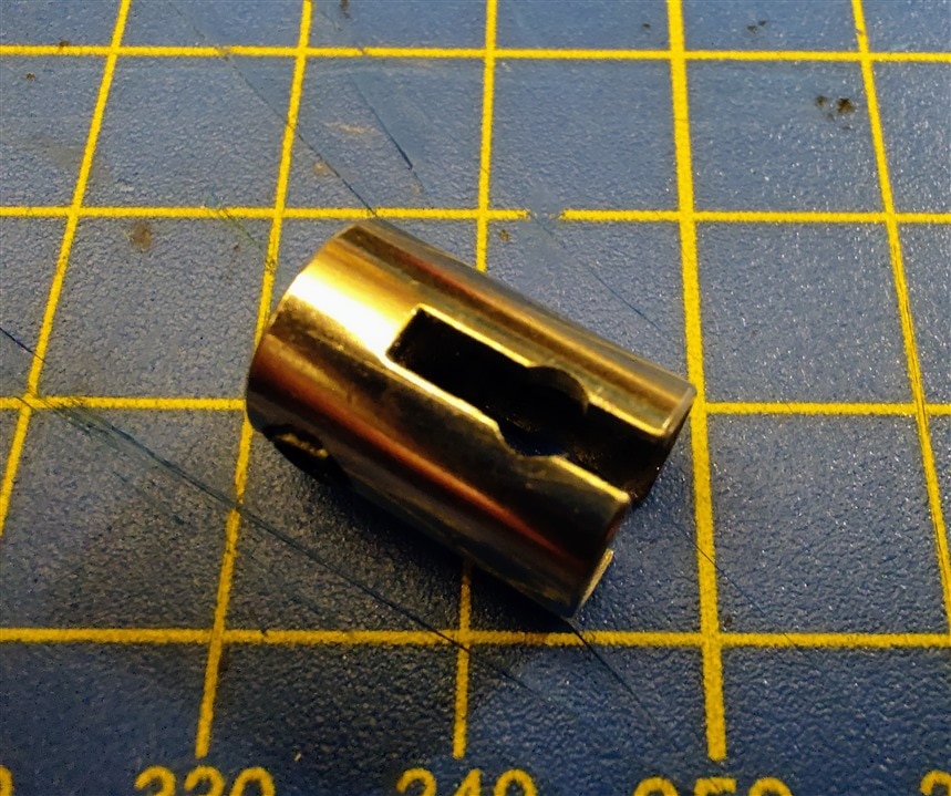
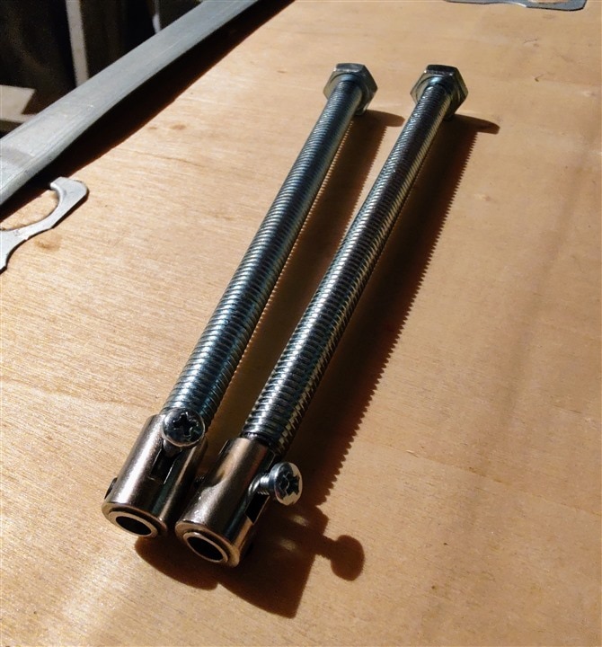
This is where things get a bit more tricky. They get tricky because we need a way to connect the M8 bolts with the differential. One way of doing this would be designing and printing small adapters. I decided to go a different but much more robust way. The differential has a small steel coupling on each side, so with a lot of help from my dad, we turned the M8 bolts down to 6mm plus we drilled and tapped a hole for a 3mm screw to go through the center of the bolt.
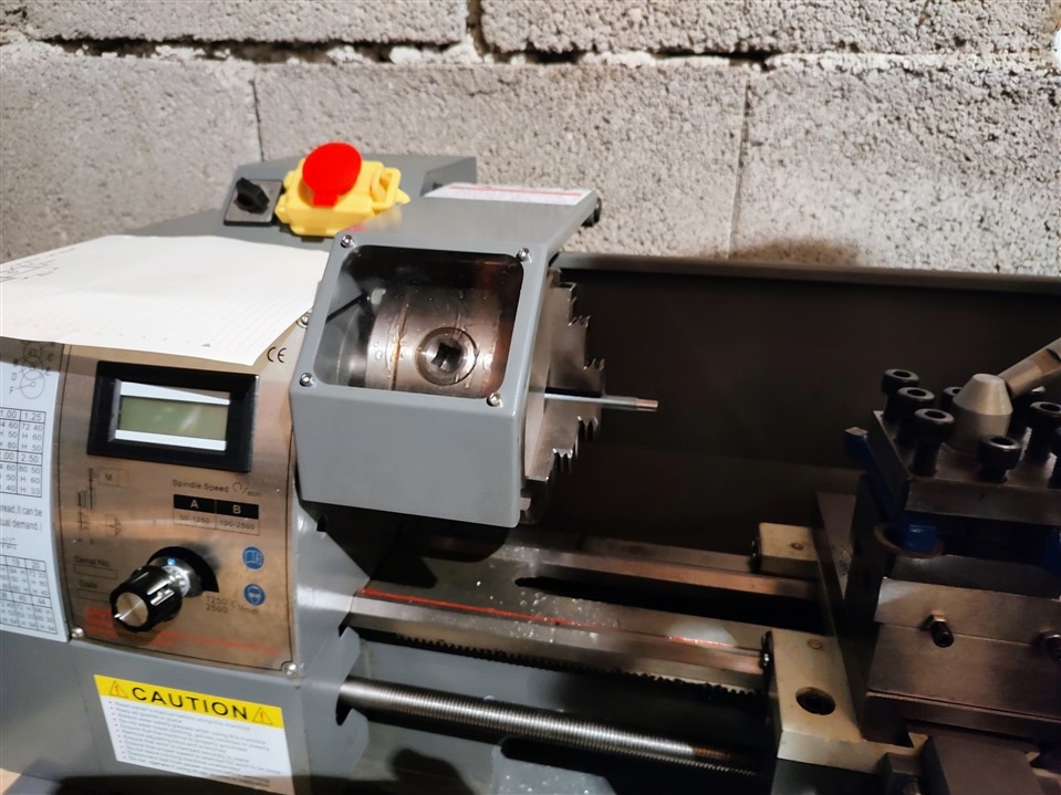
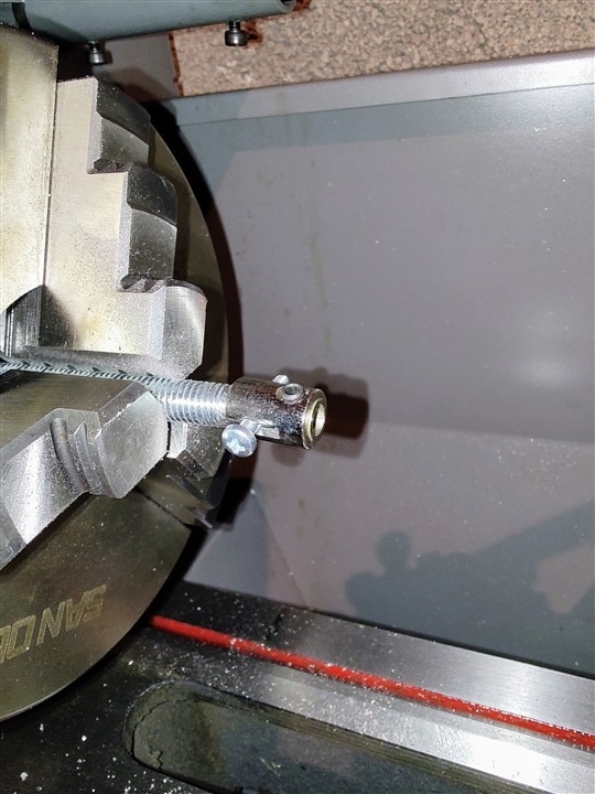
The steel couplings were a bit too small for the M3 screw, so I used a Dremel and one of those diamond bits to just make a small hole for the M3 screw.
With all of that done, here is how the suspension part looks assembled.
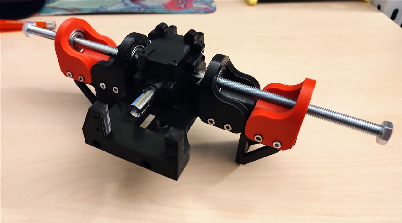
5. Assembled rover and suspension test
With all of that done (the gearbox part 4 times) I put everything together for the first part and here is how it turned out in real life!
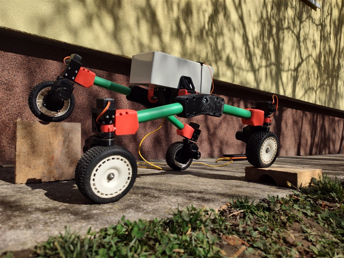
And here it is! I was so thrilled to see it on its wheels for the first time. It's one thing seeing it on the screen at different iterations and a completely different thing seeing it standing beside me. There are a few things that I of course see now after building it that I want to change, but those are some small things that will be fixed by the next blog. For example, the wheels on the outside get a bit too close for comfort, but that's a simple spacer that I can print and the problem will be fixed. I love the suspension setup and how it conforms to anything.
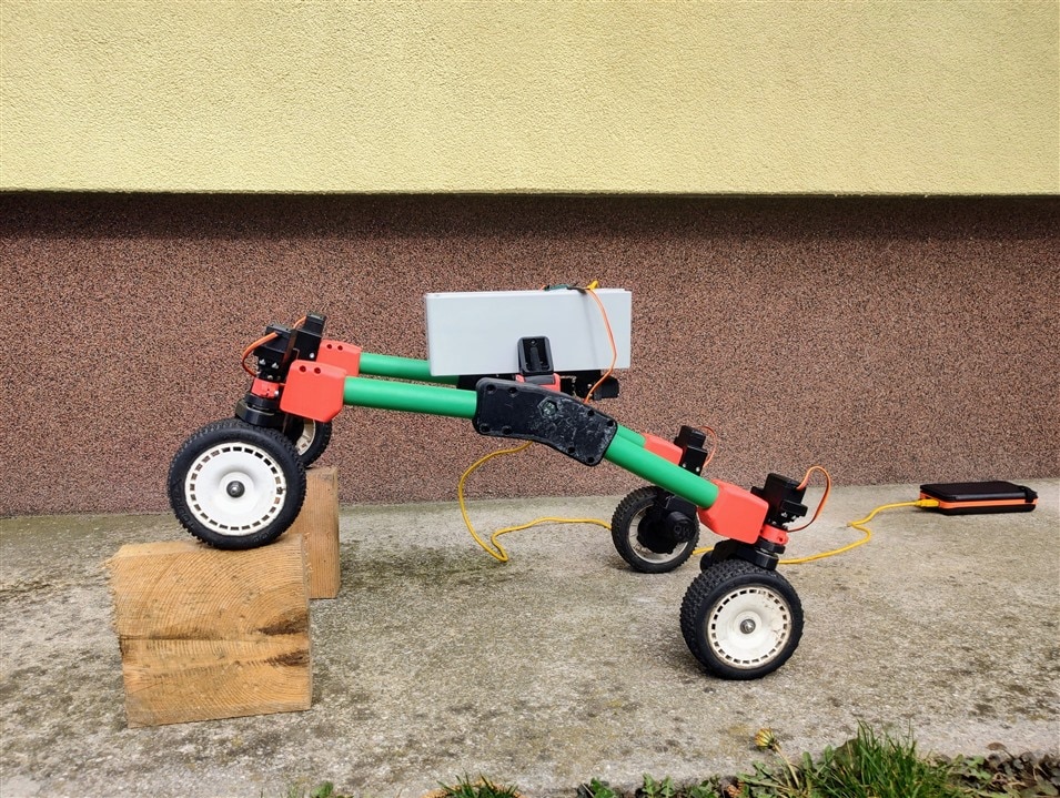
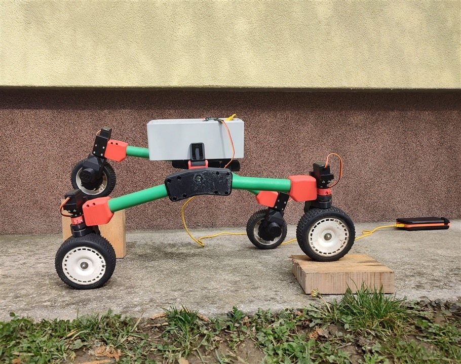
One thing you might notice in the pictures above is a yellow cable and that the box is completely level in both pictures. I assembled everything with the continuous servo underneath, so I thought I might as well do a fast setup to see how well the rover could balance the body. To do this, I attached an MPU6050 IMU inside the enclosure and put an Arduino Mega inside. To keep it level, I wrote a small code that implements a PI regulator for keeping it level, and as you will see in the video it needs some tuning, but I will do that once all of the electronics are on board. Here is the code for the PI regulator as well as the video of the active suspension.
// Basic demo for accelerometer readings from Adafruit MPU6050
#include <Servo.h>
#include <Adafruit_MPU6050.h>
#include <Adafruit_Sensor.h>
#include <Wire.h>

Adafruit_MPU6050 mpu;
Servo myServo;

float reference = 0.0;
float kp = 10.0;
float ki = 0.12;
float e = 0.0;
float angle = 0.0;
int servoCommand = 0.0;
float servoStationary = 90.0;
float intSum = 0.0;

void setup(void) {
  Serial.begin(115200);
  myServo.attach(2);
  myServo.write(90);
  while (!Serial) {
    delay(10); // will pause Zero, Leonardo, etc until serial console opens
  }

  // Try to initialize!
  if (!mpu.begin()) {
    Serial.println("Failed to find MPU6050 chip");
    while (1) {
      delay(10);
    }
  }

  mpu.setAccelerometerRange(MPU6050_RANGE_16_G);
  mpu.setGyroRange(MPU6050_RANGE_250_DEG);
  mpu.setFilterBandwidth(MPU6050_BAND_21_HZ);
  Serial.println("");
  delay(100);
}

void loop() {

  /* Get new sensor events with the readings */
  sensors_event_t a, g, temp;
  mpu.getEvent(&a, &g, &temp);
  angle = a.acceleration.x;
  /* Print out the values */
  Serial.print(angle);
  Serial.println("");

  e = reference - angle;
  intSum += e;
  servoCommand = servoStationary + round(e*kp + ki*intSum);

  if(servoCommand > 180 || servoCommand < 0)
  {
    intSum -= e;
    servoCommand -= ki*e;
    }

  myServo.write(servoCommand);


  delay(10);
}
And here is a video of the rover balancing:
6. Summary
This was such a rewarding part of this blog to see it finally stand on its wheels, and an even more rewarding part will be seeing the rover move for the first time, which will come in shortly! My next goal is to quickly redesign a few crucial parts that I've noticed need a touch-up and then start with the wiring and soldering so I can finally get some movement from the rover! There is a lot of work to do and not a lot of time, but it will be rewarding in the end! Thanks for reading the blog, hope you like it!
Milos
Relevant links for the competition:
- Just Encase Design Challenge
- Just Encase Design Challenge - About
- Just Encase Design Challenge - Challengers
Link to my GitHub where you can find all of the files used for this project (codes, 3D models,...):
Link to my Project Collection:
Orb-Weaver Rover - Blog #3 - Full Battery Test <----- Previous blog

