


Orbweaver Rover - Making the rover
Orb-weaver Rover - Making the Rover! <----- Previous Blog
Table of Contents
 1. Introduction
Hi! This will be my 5th blog for the Orb-weaver project. In the last blog, I covered the mechanical design and build of the rover. I went over my inspiration for the design of the rover as well as all of the 3D models I designed. The last thing I had done in the last blog was the active suspension where the rover could keep the body level, no matter the wheel positions. But one thing you can see in the last blog is the completely empty body of the rover, this is something I will be fixing in this blog, because it's time for the electronics and wiring, and since I'm writing this after I'm done with the wiring, there will be a lot of it. Before I get to that part though, let's take a look at the schematics for the inside of the rover as well as how I plan on mounting them inside the rover.
2. Electronics inside the rover
My initial plan for the rover was to have an Arduino Mega 2560 for communicating with all of the different motors and stuff like that (because of the sheer amount of pins), an Arduino MKR WAN 1300 for using the rover with LoRa and a Raspberry Pi 4 for ROS. While I have set up ROS a while back and had a few successful tests with the LIDAR, I don't have time to integrate it properly at the moment, so for now, I will be sticking only with the 2 Arduinos. Here is a full list of necessary components for the build (excluding the connectors and stuff like that):
- Arduino MEGA 2560
- Arduino MKR WAN1300
- Antenna for Arduino MKR WAN1300
- 2 x L298N Motor Driver
- Buck Converter (I got an 8A one)
- MPU6050

As I've said above, a lot of soldering and connector crimping. One thing to point out that isn't shown here is that the Arduino Mega 2560 can't be directly connected to the Arduino MKR WAN via Rx, Tx pins since they are on different voltage levels, 5V and 3.3V. To overcome this, I used a voltage divider on the Arduino MKR Rx pin (3.3k and 2k), while the 3.3V is enough to trigger the Arduino Mega Rx pin.
Each of the servo motors requires a PWM pin for controlling the position or speed in the case of the suspension servo motor. As for the drive motors, 2 of them are connected to an L298N motor driver. The driver has 6 pins for controlling the motors besides the voltage supply, 3 pins for each motor. Each motor will have an EN pin and IN1 and IN2 pins. Using the IN1 and IN2 pins we can alter the direction of the rotation of the motor, they are always opposite of each other (if IN1 is HIGH, then IN2 is LOW). We use the EN pin for controlling the speed of the motors using a PWM signal. This is why I had to go with an Arduino Mega or use a separate Servo Motor Driver. To be any chance of this working, and to make it easier to troubleshoot if needed (it was needed of course) let's find the best way for packaging everything.
3. Packaging the electronics
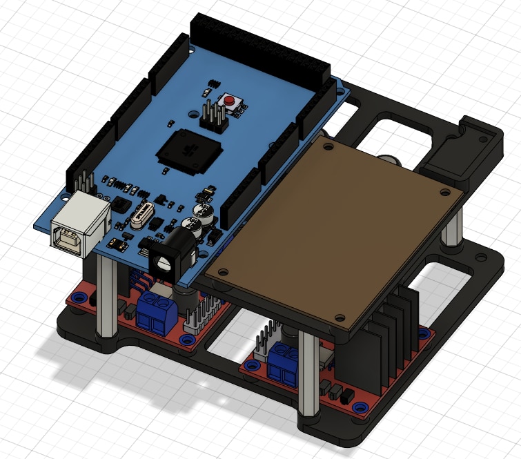
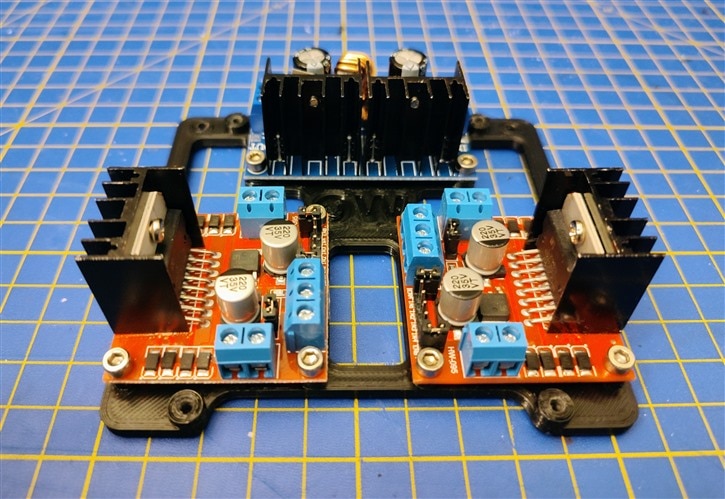
For this, I of course started in Fusion with the model of the Hammond Enclosure. I can't stress enough how useful it was to have the models available on the site for download, rather than trying to measure every dimension by hand. I went for a 2 story approach where on the bottom level I would have the 2 motor drivers and the buck converter, while on the top level, I'll have the 2 Arduinos and the IMU.
1st Level


For mounting this level, I used the 2 holes with threaded inserts on one side of the box. To mount the second level, I used 4 30mm standoffs, any more than that, and I would have issues with clearances at the top.
2nd Level

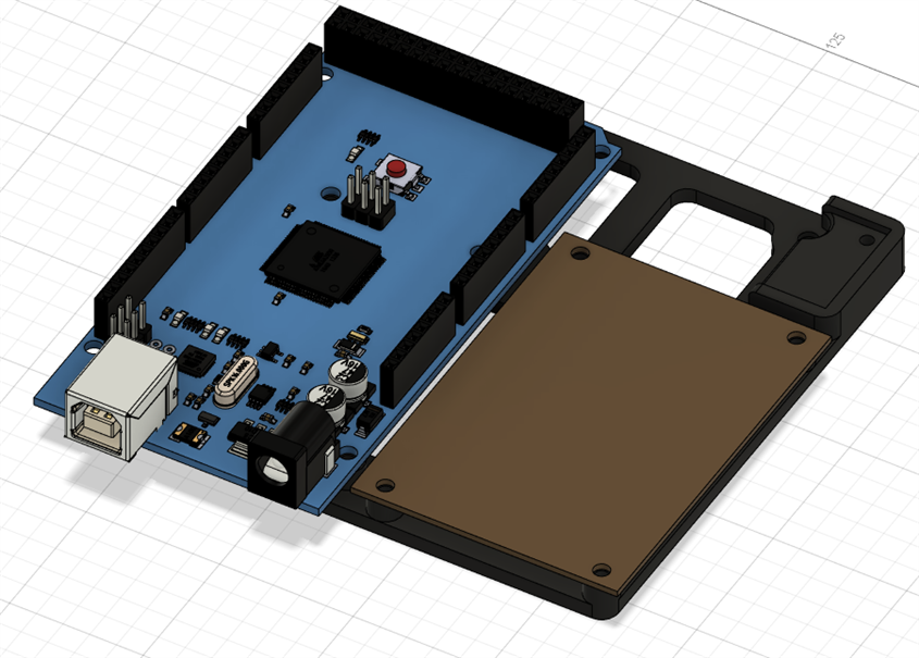
This level mounts to the mentioned posts and has mounting holes for the Arduino Mega, a perfboard that will hold the Arduino MKR WAN1300, and a mounting hole for the MPU6050. Here is how it all looks assembled.

Battery Mount
One important thing from the electronics that I need to mount is the battery. I decided to keep the battery on the outside of the rover for a few reasons:
- More space inside the body for other electronics
- Easier to disconnect and charge
- Easier to turn off the rover
The battery is mounted using a 2 piece 3D printed mount that I attached to the bottom of the enclosure with a couple of M3 screws. One great thing about the enclosure is how thick the walls are, which means that I was able to cut some really strong threads into the walls and the bottom of the enclosure.


Here is a short video of how this all goes together:
4. Building and Wiring
All that's left now is to build and wire up everything. Before I get to the wiring part of the build, last time I didn't yet mount the suspension to the enclosure and didn't drill the holes for the cable glands, so this is the first thing I will do.
Mounting the suspension to the enclosure
To begin with, mounting the suspension, I got all of the dimensions from Fusion and drew them on a piece of paper that I glues to the bottom of the enclosure using some double-sided sticky tape. This way I can easily drill all of the holes without having any alignment issues later.


After that was done, I had to thread the holes for M3 screws and then I can mount the suspension for the first time. After doing that I also positioned and drilled the holes for the cable glands I was planning on using for the cables that come from all of the motors.


Wiring the motors
The next I had to do was wire all of the motors, which meant I had to do some soldering. The wheels were scratching a bit on the top, so to remedy that and to have a neater cable solution, I made small spacers with a hole in the middle where I glued in a small rubber cable grommet.


This gave me 3 more millimeters of clearance while also making the whole wiring look much cleaner than it would have.

The last thing to do was to get all of the cables through the pipes to the center where I used some automotive black tape and heat shrink to get everything nice and tidy.


Mounting the electronics

Before getting any further with mounting the electronics, we need to do some wiring on the other side. To make things a bit easier, I made a small board with a lot of connectors for supplying the power to the different parts of the rover as well as the connector for all of the servo motors. The servos tend to draw a lot of current when starting to move sometimes, so I added a capacitor for every 2 servo connectors.


Another thing I did was print a small label for each cable. This made my life so much easier when trying to connect everything later. For the most part, I stuck with the nylon crimp connectors since they are really easy to crimp and I love using them. I haven't connected the motor sensor wires, because there isn't any point to it when we consider that the rubber bands can slip, this is something I will do once I switch to the geared gearboxes.

The only thing left now is the top floor with the Arduinos.

I later realized that I'll need more cables going out of the rover for the sensors and stuff like that, so I added 2 more cable glands and a connector for the battery. I made sure to drill all of the holes I could on the bottom of the rover since they are the least likely to get wet. As it stands, the rover would be pretty resistant, I would only need to tackle the servos and seal the gearboxes a bit, but there are some simple ways of doing this.


5. Programming
With all of the hardware done, it was time to do software a bit more. These are the current versions of the code that I will be updating shortly. For now, the GCS can listen for the data coming from the sensor boxes and we can send commands using the GCS and LoRa over to the rover. The Arduino MKR WAN on the rover functions currently as a LoRa receiver that takes those commands and sends them using UART to the Arduino Mega. The Arduino Mega listens for commands on Serial1 and controls all of the motors on the rover.
GCS
#include <SPI.h>
#include <LoRa.h>
#include <Wire.h>
#include "rgb_lcd.h"
#include "TM1651.h"

#define CLK 3    //pins definitions for TM1651 and can be changed to other ports
#define DIO 4
#define BUZZER 5
TM1651 batteryDisplay(CLK,DIO);

String inputString = "";
bool stringComplete = false;

int batLevel = 0;
long previousTime = 0;
bool risingLevel = true;
int packetNumber = 0;

rgb_lcd lcd;

const int colorR = 200;
const int colorG = 50;
const int colorB = 150;

void setup() {
  // put your setup code here, to run once:
  pinMode(BUZZER, OUTPUT);
  Serial.begin(9600);
  lcd.begin(16, 2);
  lcd.setRGB(colorR, colorG, colorB);
  batteryDisplay.init();
  batteryDisplay.set(7);//set brightness: 0---7
  if (!LoRa.begin(915E6)) {
    Serial.println("Starting LoRa failed!");
    while (1);
  }
}

void sendLoraMessage(String message)
{
  LoRa.beginPacket();
  LoRa.print(message);
  LoRa.endPacket();
}

void loop() {
  // put your main code here, to run repeatedly:
  if(stringComplete == false)
  {
    char c = 'a';
    if(Serial.available() != 0)
    {
      c = (char)Serial.read();
      inputString += c;
    }
    if(c == '\n')
    {
      stringComplete = true;
    }

  }
  else
  {
    Serial.println(inputString);
    lcd.clear();
    lcd.setCursor(0, 0);
    lcd.print(inputString.substring(0, inputString.length() - 1));
    sendLoraMessage(inputString);
    inputString = "";
    stringComplete = false;
  }

  if(millis() - previousTime >= 1000)
  {
    if(risingLevel == true)
    {
    batLevel++;
    if(batLevel == 7) risingLevel = false;
    if(batLevel == 7) beepSiren();
    }
    else
    {
    batLevel--;
    if(batLevel == 0) risingLevel = true;
    if(batLevel == 0) beepSiren();
    }
    batteryDisplay.displayLevel(batLevel);
    previousTime = millis();
  }
  // try to parse packet
  int packetSize = LoRa.parsePacket();
  if (packetSize) {
    // received a packet
    Serial.print("Received packet '");

    // read packet
    while (LoRa.available()) {
      char inChar = (char)LoRa.read();
      Serial.print(inChar);
      inputString += inChar;
    }

    // print RSSI of packet
    Serial.print("' with RSSI ");
    Serial.println(LoRa.packetRssi());

    packetNumber++;
    lcd.clear();
    lcd.setCursor(0, 0);
    lcd.print("Received package with ID:");
    lcd.setCursor(0, 1);
    int pos = inputString.indexOf("&EID");
    lcd.print(inputString.substring(4,pos));
    inputString = "";
  }

}

void beepSiren()
{
  return;
  digitalWrite(BUZZER, HIGH);
  delay(200);
  digitalWrite(BUZZER, LOW);
  delay(100);
  digitalWrite(BUZZER, HIGH);
  delay(200);
  digitalWrite(BUZZER, LOW);
  delay(100);
}
Arduino MKR WAN - Rover
#include <SPI.h>
#include <LoRa.h>

void setup() {
  Serial1.begin(9600);

  if (!LoRa.begin(915E6)) {
    while (1);
  }
}

void loop() {
  // try to parse packet
  int packetSize = LoRa.parsePacket();
  if (packetSize) {
    // received a packet
    Serial1.print("Received packet '");

    // read packet
    while (LoRa.available()) {
      Serial1.print((char)LoRa.read());
    }

    // print RSSI of packet
    Serial1.print("' with RSSI ");
    Serial1.println(LoRa.packetRssi());
  }
}
Arduino Mega 2560
// Libraries
#include <Servo.h>
#include <Adafruit_MPU6050.h>
#include <Adafruit_Sensor.h>
#include <Wire.h>

// Pins
// Drive Motor EN Pins
#define M1 2
#define M2 3
#define M3 4
#define M4 5

// Drive Motor Direction Pins
#define M1_IN1 22
#define M1_IN2 23
#define M2_IN1 24
#define M2_IN2 25
#define M3_IN1 26
#define M3_IN2 27
#define M4_IN1 28
#define M4_IN2 29

// Steering Servo Pins
#define S1 6
#define S2 7
#define S3 8
#define S4 9

// Steering Servo Center Positions
#define s1_center 85
#define s2_center 80
#define s3_center 95
#define s4_center 85

// Suspension & Claw Servo Pins
#define S5 10
#define S6 11

// Suspension Servo Stationary Point
#define s6_stationary 90

// All of the servos
Servo s1, s2, s3, s4, s5, s6;

// IMU
Adafruit_MPU6050 mpu;

// PI suspension regulator
float kp          = 10.0;
float ki          = 0.12;
float e           = 0.0;
float pitch       = 0.0;
float roll        = 0.0;
int servoCommand  = 0.0;
float intSum      = 0.0;

String inputString = "";         // a String to hold incoming data
bool stringComplete = false;  // whether the string is complete

bool activeCommand = false;
long cmd_start_time = 0;
int cmd_length = 0;
bool ta_cmd = false;

// Function for controlling the motor direction
void setMotorDirection(int motor, int dir)
{
  // Motor can take values: 1, 2, 3, 4  - Number of the motor
  // Dir can take values: 1, 0          - 1 forward, 0 reverse

  if(motor != 1 && motor != 2 && motor != 3 && motor != 4)
  {
    Serial.println("Motor number doesn't exist");
    return;
    }

  if(dir != 0 && dir != 1)
  {
    Serial.println("Direction unrecognized");
    return;
    }

  switch(motor)
  {
    case 1:
      // Now we check the direction input
      if(dir == 0)
      {
        digitalWrite(M1_IN1, LOW);
        digitalWrite(M1_IN2, HIGH);
        }
        else
        {
          digitalWrite(M1_IN1, HIGH);
          digitalWrite(M1_IN2, LOW);
          }
          break;
    case 2:
      // Now we check the direction input
      if(dir == 0)
      {
        digitalWrite(M2_IN1, HIGH);
        digitalWrite(M2_IN2, LOW);
        }
        else
        {
          digitalWrite(M2_IN1, LOW);
          digitalWrite(M2_IN2, HIGH);
          }
          break;
    case 3:
      // Now we check the direction input
      if(dir == 0)
      {
        digitalWrite(M3_IN1, LOW);
        digitalWrite(M3_IN2, HIGH);
        }
        else
        {
          digitalWrite(M3_IN1, HIGH);
          digitalWrite(M3_IN2, LOW);
          }
          break;
    case 4:
      // Now we check the direction input
      if(dir == 0)
      {
        digitalWrite(M4_IN1, HIGH);
        digitalWrite(M4_IN2, LOW);
        }
        else
        {
          digitalWrite(M4_IN1, LOW);
          digitalWrite(M4_IN2, HIGH);
          }
          break;
    default:
      Serial.println("Error in motor switch");
      return;
    }
  }

// Function for controlling the motors
void motorControl(int motor, int dir, int pwr)
{
  // Motor can take values: 1, 2, 3, 4  - Number of the motor
  // Dir can take values: 1, 0          - 1 forward, 0 reverse
  // PWR can take vaues: 0 - 255        - 0 - 0%, 255 - 100%
  if(motor != 1 && motor != 2 && motor != 3 && motor != 4)
  {
    Serial.println("Motor number doesn't exist");
    return;
    }

  if(dir != 0 && dir != 1)
  {
    Serial.println("Direction unrecognized");
    return;
    }

  if(pwr < 0 || pwr > 255)
  {
    Serial.println("Motor power out of range");
    return;
    }

  setMotorDirection(motor, dir);

  switch(motor)
  {
    case 1:
      analogWrite(M1, pwr);
      break;
    case 2:
      analogWrite(M2, pwr);
      break;
    case 3:
      analogWrite(M3, pwr);
      break;
    case 4:
      analogWrite(M4, pwr);
      break;
    default:
      Serial.println("Motor Swtich Error");
      return;
    }

  }

// Function for clipping the servo angle to 0-180 range
int clip_angle(int center, int angle){
    if(angle + center > 180)  return 180;
    if(angle + center < 0)    return 0;
    return center + angle;
  }

// Function for steering each of the servo motors
void steerServo(int servo_motor, int angle)
{
  // Servo_Motor can take values: 1, 2, 3, 4  - Number of the motor
  // Angle can take values: -90 - 90          - 0 is the center position for the servo
  if(servo_motor != 1 && servo_motor != 2 && servo_motor != 3 && servo_motor != 4)
  {
    Serial.println("Servo motor number doesn't exist");
    return;
    }
  if(angle < -90 || angle > 90)
  {
    Serial.println("Servo angle out of range");
    return;
    }

  switch(servo_motor)
  {
    case 1:
      s1.write(clip_angle(s1_center, angle));
    case 2:
      s2.write(clip_angle(s2_center, angle));
    case 3:
      s3.write(clip_angle(s3_center, angle));
    case 4:
      s4.write(clip_angle(s4_center, angle));
    default:
      Serial.println("Servo motor switch error");
      break;
    }

  }

// Function for controlling the angle of the rover body - the active suspension
void activeSuspension(int reference)
{
  // Getting the IMU data
  sensors_event_t a, g, temp;
  mpu.getEvent(&g, &a, &temp);
  roll  = g.gyro.x;
  pitch = g.gyro.y;

  // Calculating the error e
  e = -1 * (reference - pitch);
  intSum += e;
  servoCommand = s6_stationary + round(e * kp + ki * intSum);

  if(servoCommand > 180 || servoCommand < 0)
  {
    intSum -= e;
    servoCommand -= ki*e;
    }

  s6.write(servoCommand);
  }

// This function is triggered if the Arduino detects anything on the Serial1 port
void serialEvent1() {
  while (Serial1.available()) {
    // get the new byte:
    char inChar = (char)Serial1.read();
    // add it to the inputString:
    inputString += inChar;
    // if the incoming character is a newline, set a flag so the main loop can
    // do something about it:
    if (inChar == '\n') {
      stringComplete = true;
    }
  }
}

// Function for moving the rover
void moveRover(int dir, int motor_speed, int spin_time)
{

  if(activeCommand == false)
  {
    cmd_start_time = millis();
    cmd_length = spin_time;
    activeCommand = true;
    motorControl(1, dir, motor_speed);
    motorControl(2, dir, motor_speed);
    motorControl(3, dir, motor_speed);
    motorControl(4, dir, motor_speed);
  }

}

void turnRover(int dir, int motor_speed_num, int spin_time)
{
  steerServo(1, 57);
  steerServo(2, -57);
  steerServo(3, 57);
  steerServo(4, -57);

  cmd_start_time = millis();
  cmd_length = spin_time;
  activeCommand = true;
  ta_cmd = true;

  if(dir == 0)
  {
    motorControl(1, 0, motor_speed_num);
    motorControl(2, 0, motor_speed_num);
    motorControl(3, 1, motor_speed_num);
    motorControl(4, 1, motor_speed_num);
  }
  else
  {
    motorControl(1, 1, motor_speed_num);
    motorControl(2, 1, motor_speed_num);
    motorControl(3, 0, motor_speed_num);
    motorControl(4, 0, motor_speed_num);
  }


}

// Function that checks if the rover has been moving for as long as it has too
void stopRover()
{
  if(activeCommand == true)
  {
    if(cmd_length < millis() - cmd_start_time)
    {
      stopAllMotors();
      activeCommand = false;

      if(ta_cmd == true)
      {
        steerServo(1, 0);
        steerServo(2, 0);
        steerServo(3, 0);
        steerServo(4, 0);
        ta_cmd = false;
      }
    }
  }
  return;
}

void stopAllMotors()
{
  motorControl(1, 1, 0);
  motorControl(2, 1, 0);
  motorControl(3, 1, 0);
  motorControl(4, 1, 0);
}

// Function for extracting the command
void extractCommand(String message)
{
  if(message.indexOf("&RoverCommand") == -1)
  {
    // This is the case where we haven't received a message that is a command
    Serial.println("This is not a rover command");
    return;
  }

  int cs = message.indexOf("&CS");
  String cmd = message.substring(cs + 3, cs + 4);
  Serial.println(cmd);
  if(cmd == "X")
  {
    // This is an emergency STOP command
    stopAllMotors();
    return;
  }
  else if(cmd == "M")
  {
    // This means that we have received a move command
    Serial.println("Move command");

    // We need to extract the data from that message
    int ds = message.indexOf("&DS");
    int d1 = message.indexOf(";");
    int d2 = message.indexOf(":");
    int de = message.indexOf("&DE");

    // Extracting the data as strings
    String dir          = message.substring(ds + 3, d1);
    String motor_speed  = message.substring(d1 + 1, d2);
    String spin_time    = message.substring(d2 + 1, de);

    // Converting all of the data to int
    int dir_num = dir.toInt();
    int motor_speed_num = motor_speed.toInt();
    int spin_time_num = spin_time.toInt();

    Serial.println(dir_num);
    Serial.println(motor_speed_num);
    Serial.println(spin_time_num);

    // Using the move command
    moveRover(dir_num, motor_speed_num, spin_time_num);
  }
  else if(cmd == "S")
  {
    int ds = message.indexOf("&DS");
    int de = message.indexOf("&DE");

    String angle_cmd =  message.substring(ds + 3, de);

    int angle_num = angle_cmd.toInt();

    steerServo(1, angle_num);
    steerServo(2, -angle_num);
    steerServo(3, -angle_num);
    steerServo(4, angle_num);

    return;
  }
  else if(cmd == "T")
  {
    // This means that we have received a move command
    Serial.println("Turn in place command");

    // We need to extract the data from that message
    int ds = message.indexOf("&DS");
    int d1 = message.indexOf(";");
    int d2 = message.indexOf(":");
    int de = message.indexOf("&DE");

    // Extracting the data as strings
    String dir          = message.substring(ds + 3, d1);
    String motor_speed  = message.substring(d1 + 1, d2);
    String spin_time    = message.substring(d2 + 1, de);

    // Converting all of the data to int
    int dir_num = dir.toInt();
    int motor_speed_num = motor_speed.toInt();
    int spin_time_num = spin_time.toInt();

    Serial.println(dir_num);
    Serial.println(motor_speed_num);
    Serial.println(spin_time_num);

    turnRover(dir_num, motor_speed_num, spin_time_num);
  }
  else if(cmd == "P")
  {

  }
  else
  {
    Serial.println("Unrecognized command");
  }
}

void setup() {

  // Serial
  Serial.begin(9600);
  Serial1.begin(9600);
  inputString.reserve(200); // This is for the message that comes from the Arduino MKR WAN 1300

  // Setting up the pins
  // Motor 1 pins
  pinMode(M1,     OUTPUT);
  pinMode(M1_IN1, OUTPUT);
  pinMode(M1_IN2, OUTPUT);

  // Motor 2 pins
  pinMode(M2,     OUTPUT);
  pinMode(M2_IN1, OUTPUT);
  pinMode(M2_IN2, OUTPUT);

  // Motor 3 pins
  pinMode(M3,     OUTPUT);
  pinMode(M3_IN1, OUTPUT);
  pinMode(M3_IN2, OUTPUT);

  // Motor 4 pins
  pinMode(M4,     OUTPUT);
  pinMode(M4_IN1, OUTPUT);
  pinMode(M4_IN2, OUTPUT);

  // Attaching the Sevos
  s1.attach(S1);
  s2.attach(S2);
  s3.attach(S3);
  s4.attach(S4);
  s5.attach(S5);
  s6.attach(S6);

  // Centering the servos
  steerServo(1, 0);
  steerServo(2, 0);
  steerServo(3, 0);
  steerServo(4, 0);

  // Putting the suspension servo in stationary
  s6.write(s6_stationary);

  // Putting all of the motors to forward and shutting them down
  motorControl(1, 1, 0);
  motorControl(2, 1, 0);
  motorControl(3, 1, 0);
  motorControl(4, 1, 0);

  // Try to initialize the IMU
  if (!mpu.begin()) {
    Serial.println("Failed to find MPU6050 chip");
    while (1) {
      delay(10);
    }
  }

  mpu.setAccelerometerRange(MPU6050_RANGE_16_G);
  mpu.setGyroRange(MPU6050_RANGE_250_DEG);
  mpu.setFilterBandwidth(MPU6050_BAND_21_HZ);

  delay(2000);

}

void loop() {

  activeSuspension(0.00);

  stopRover();

  if (stringComplete) {
    Serial.println(inputString);
    extractCommand(inputString);
    // clear the string:
    inputString = "";
    stringComplete = false;
  }

  delay(10);

}
6. Testing
With all of that done, we come to the fun part finally, after many weeks of first coming up with the design and then slowly building it up part by part. We can finally drive the rover around and test it out a bit. To send these commands I connected my laptop to the GCS and used the Serial monitor, the end goal is for the rover to be autonomous, but also, we should be able to send the commands using the GUI that I showed in blog #2.
Steering Test
Turning in place Test
Driving around Test
7. Summary
It was so rewarding to see the rover move after all of those hours that I've put into it. While the rubber band system isn't ideal and I had to replace a few after snapping it still drives really nicely. These were some basic maneuvers, but I plan on adding more precise steering with calculated angles as I've shown in blog #1. There isn't much time left in this challenge, so tomorrow will be my last blog for this competition where I'll go over the updated GUI and do a more thorough test of the whole system. Thanks for reading the blog, hope you liked it!
Milos
Relevant links for the competition:
- Just Encase Design Challenge
- Just Encase Design Challenge - About
- Just Encase Design Challenge - Challengers
Link to my GitHub where you can find all of the files used for this project (codes, 3D models,...):
Link to my Project Collection:
Top Comments