element14 Community
element14 Community
    Register Log In
  • Site
  • Search
  • Log In Register
  • Community Hub
    Community Hub
    • What's New on element14
    • Feedback and Support
    • Benefits of Membership
    • Personal Blogs
    • Members Area
    • Achievement Levels
  • Learn
    Learn
    • Ask an Expert
    • eBooks
    • element14 presents
    • Learning Center
    • Tech Spotlight
    • STEM Academy
    • Webinars, Training and Events
    • Learning Groups
  • Technologies
    Technologies
    • 3D Printing
    • FPGA
    • Industrial Automation
    • Internet of Things
    • Power & Energy
    • Sensors
    • Technology Groups
  • Challenges & Projects
    Challenges & Projects
    • Design Challenges
    • element14 presents Projects
    • Project14
    • Arduino Projects
    • Raspberry Pi Projects
    • Project Groups
  • Products
    Products
    • Arduino
    • Avnet Boards Community
    • Dev Tools
    • Manufacturers
    • Multicomp Pro
    • Product Groups
    • Raspberry Pi
    • RoadTests & Reviews
  • About Us
  • Store
    Store
    • Visit Your Store
    • Choose another store...
      • Europe
      •  Austria (German)
      •  Belgium (Dutch, French)
      •  Bulgaria (Bulgarian)
      •  Czech Republic (Czech)
      •  Denmark (Danish)
      •  Estonia (Estonian)
      •  Finland (Finnish)
      •  France (French)
      •  Germany (German)
      •  Hungary (Hungarian)
      •  Ireland
      •  Israel
      •  Italy (Italian)
      •  Latvia (Latvian)
      •  
      •  Lithuania (Lithuanian)
      •  Netherlands (Dutch)
      •  Norway (Norwegian)
      •  Poland (Polish)
      •  Portugal (Portuguese)
      •  Romania (Romanian)
      •  Russia (Russian)
      •  Slovakia (Slovak)
      •  Slovenia (Slovenian)
      •  Spain (Spanish)
      •  Sweden (Swedish)
      •  Switzerland(German, French)
      •  Turkey (Turkish)
      •  United Kingdom
      • Asia Pacific
      •  Australia
      •  China
      •  Hong Kong
      •  India
      •  Korea (Korean)
      •  Malaysia
      •  New Zealand
      •  Philippines
      •  Singapore
      •  Taiwan
      •  Thailand (Thai)
      • Americas
      •  Brazil (Portuguese)
      •  Canada
      •  Mexico (Spanish)
      •  United States
      Can't find the country/region you're looking for? Visit our export site or find a local distributor.
  • Translate
  • Profile
  • Settings
Light Up Your Life
  • Challenges & Projects
  • Design Challenges
  • Light Up Your Life
  • More
  • Cancel
Light Up Your Life
Forum Smart car chamber #2 Drive the LEDs
  • News
  • Forum
  • Projects
  • DC
  • Leaderboard
  • Files
  • Members
  • More
  • Cancel
  • New
Join Light Up Your Life to participate - click to join for free!
Actions
  • Share
  • More
  • Cancel
Forum Thread Details
  • Replies 1 reply
  • Subscribers 46 subscribers
  • Views 72 views
  • Users 0 members are here
Related

Smart car chamber #2 Drive the LEDs

fyaocn
fyaocn 11 days ago

1 Drive the led

Normally, led can be driven with MCU directly, for some industrial MCU, 50mA can be achieved. But this is not applicable for this case ,since led in series leads to more power consumption and damage the MCU easily. 

In fact, for most ports or pins, it shall be limited to 1mA to output

2 Drive led with arduino zero

2.1 Core Architecture & Key Hardware Features

To drive an LED with an Arduino Zero, follow these steps. The Arduino Zero is a 32-bit board with 3.3V logic, so we need to ensure proper voltage handling.
Components Needed:
  • Arduino Zero
  • LED (any color)
  • 220Ω resistor (to limit current)
  • Breadboard and jumper wires
Circuit Connections:
  • Connect the long leg (anode) of the LED to one end of the 220Ω resistor.
  • Connect the other end of the resistor to a digital pin on the Arduino Zero.
  • Connect the short leg (cathode) of the LED to the GND pin on the Arduino Zero.

2.2 Codes to drive the led

Here is code for arduino zero

const int ledPin = 13;

void setup() {
  // Initialize the LED pin as an output
  pinMode(ledPin, OUTPUT);
}

void loop() {
  // Turn the LED on (HIGH means 3.3V on Arduino Zero)
  digitalWrite(ledPin, HIGH);
  delay(1000); // Wait for 1 second (1000 milliseconds)
  
  // Turn the LED off
  digitalWrite(ledPin, LOW);
  delay(1000); // Wait for 1 second
}

2.3 Arduino Zero Output Current Limits

  • Maximum current per GPIO pin: 7 mA (recommended continuous current)
  • Absolute maximum current per pin: 15 mA (exceeding this can damage the pin)
  • Total current from all GPIO pins combined: 100 mA (to avoid overloading the board's voltage regulator)
These limits are lower than some other Arduino boards (like the Uno) because the Arduino Zero uses 3.3V logic instead of 5V.
Therefore if more led in series shall be used, drive directly with arduino zero is applicable.

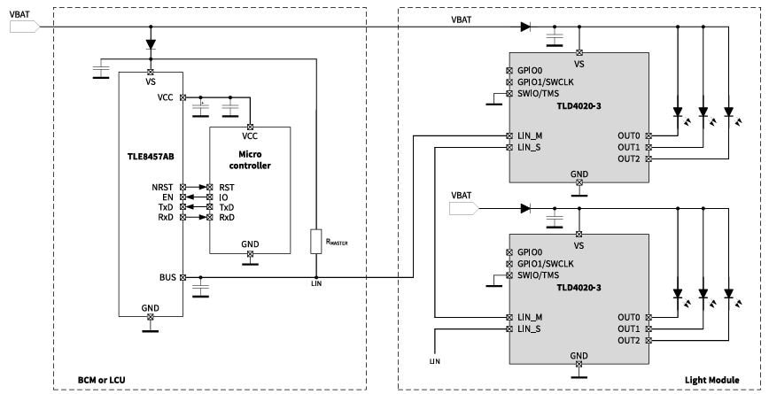
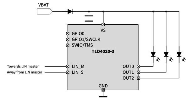
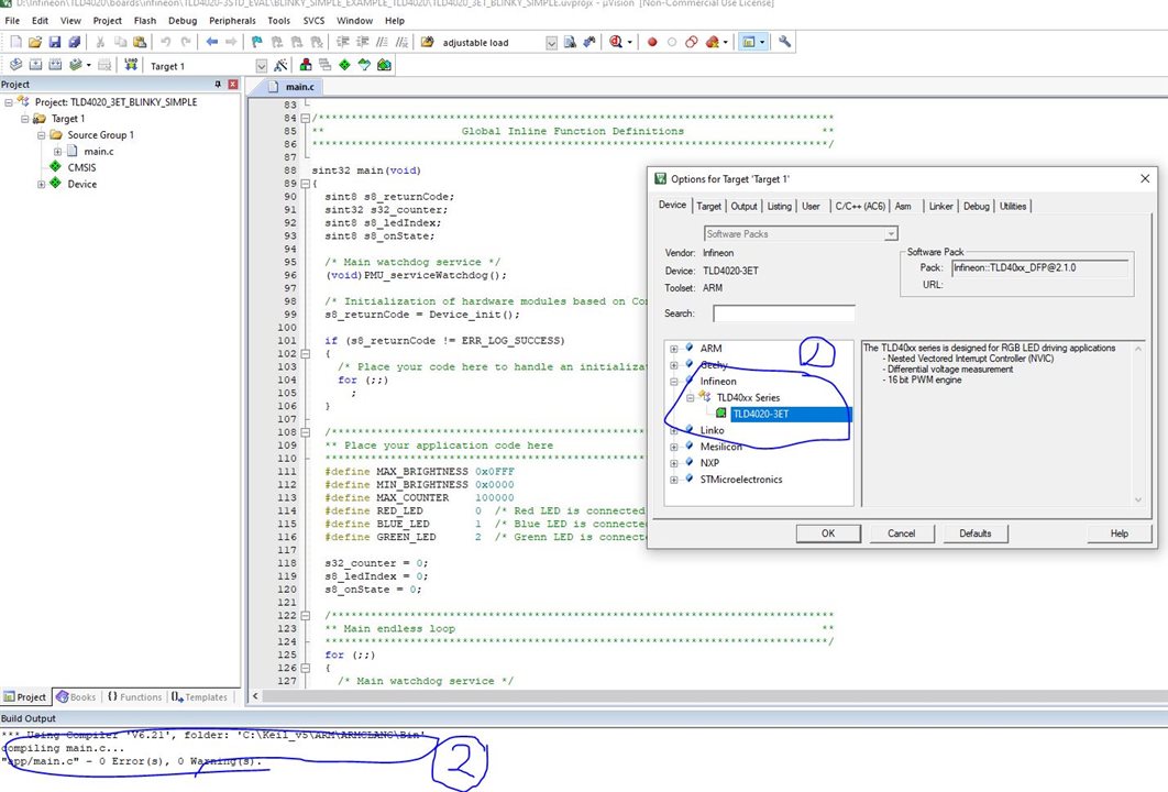
3 Introduction to TLD4020-3ET Chip

The TLD4020-3ET, developed by Infineon under its LITIXTm Interior product line, is a highly integrated, automotive-grade LED driver chip tailored for interior lighting applications. It combines a powerful microcontroller core, flexible memory resources, dedicated LED driver stages, and a LIN (Local Interconnect Network) interface, making it a compact and reliable solution for modern automotive lighting systems.
For this smart car chamber project, LIN is good choice, and widely applicable in large warehouse illumination. While LIN is not the key point in this design challenge, so, let it go for a moment.
image

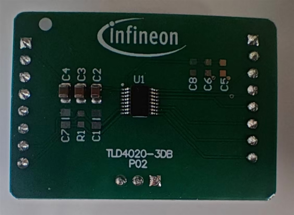
3.1 Core Architecture & Key Hardware Features

The chip’s architecture is optimized for efficient control of LED lighting, with a focus on performance, flexibility, and automotive-grade robustness.

1.1 Microcontroller (MCU) Subsystem

At its core, the TLD4020-3ET features a 32-bit Arm® Cortex®-M23 processor, designed for low-power, high-efficiency operation:
  • Adopts a "one clock per machine cycle" architecture for fast instruction execution.
  • Integrates a single-cycle multiplier and hardware divider, enabling quick mathematical computations (critical for real-time LED current/PWM control).

1.2 On-Chip Memory

It includes a complete set of memory modules to support firmware execution, data storage, and startup operations:
  • 32 kB Flash Memory: Includes 1000-cycle endurance (1000 TP) memory for critical data storage (e.g., calibration parameters).
  • 576 Bytes 1000 TP Memory: Additional dedicated memory with high endurance for frequent read/write tasks.
  • 3 kB SRAM: For temporary data storage during runtime (e.g., real-time lighting control variables).
  • Boot ROM: Preloaded with startup firmware and Flash programming routines, simplifying initialization and in-system updates.

1.3 On-Chip Peripherals & Debug Support

  • Oscillator: On-chip oscillator eliminates the need for external clock components, reducing system BOM (Bill of Materials) cost.
  • Debug Interface: Supports 2-wire SWD (Serial Wire Debug) for efficient debugging and firmware development.
  • GPIO Pins: 2 general-purpose input/output pins (GPIO0, GPIO1/SWCLK) for flexible interaction with external components (e.g., sensors, switches).

3.2 LED Driver Capabilities

The TLD4020-3ET is primarily designed as a three-channel linear current sink (LCS) for RGB or multi-color LED control, with key features:
  • Current Capacity: Each channel can drive up to 51.5 mA (absolute maximum: 56.65 mA) to power individual LEDs.
  • Parallel Configuration: Power stages can be paralleled to support higher load currents (for brighter lighting or multiple LEDs in series).
  • Precise Current Control: Each channel’s current is configurable via a 5-bit set value, enabling fine-grained brightness adjustment.
  • Independent PWM: 3 independent PWM (Pulse-Width Modulation) configurations, allowing dynamic light pattern control (e.g., dimming, color mixing for RGB LEDs).

3.3  Communication Interface(Not used in this design)

The chip integrates a LIN transceiver (with LIN_M and LIN_S pins) to enable seamless communication with the vehicle’s main network:
  • Programming: Supports firmware updates via the LIN interface (using a bootloader), eliminating the need for dedicated programming ports.
  • Control: Receives lighting commands (e.g., "turn on contour lighting") from the LIN master (e.g., vehicle ECU).
  • Diagnostics: Sends feedback (e.g., LED fault status, current levels) to the master, enabling predictive maintenance and system monitoring.

image

3.4 Automotive-Grade Reliability & Compliance

The TLD4020-3ET meets strict automotive industry standards, ensuring stability in harsh vehicle environments, this is idea in smart car chamber. As far as one can see, most of luxurious car brand such as Mercedes Benz have introduced smart ambient illumination effect in the cars ,here is the parameters,
  • AEC-Q100 Qualification: Grade 1 compliance, meaning it operates reliably across a junction temperature range of -40°C to +150°C (ambient temperature: -40°C to +125°C).
  • Robust Electrical Protection:
    • Supply voltage (VS) tolerance: -0.3 V to 40 V (supports suppressed load dump per ISO 16750-2).
    • ESD Susceptibility: 2 kV (HBM, all pins), 8 kV (HBM, LIN vs GND), and 500 V (CDM, all pins) – protecting against electrostatic discharge.
  • RoHS Compliance: Lead-free (Pb-free) finish on leads, suitable for Pb-free soldering (per IPC/JEDEC J-STD-020), meeting global environmental regulations.

3.5 Typical Applications

The TLD4020-3ET is optimized for automotive interior lighting scenarios, including:
  • RGB LED control for ambient or mood lighting.
  • Contour lighting (single light source with constant/slowly changing patterns).
  • Functional lighting (e.g., dashboard indicators, door handle illumination).
  • Surface lighting requiring single LEDs (e.g., center console backlighting).

image

In summary, the TLD4020-3ET integrates MCU, memory, LED drivers, and LIN communication into a single chip, offering a cost-effective, reliable, and flexible solution for next-generation automotive interior lighting systems.

3.6 Drive the RGB led in three channels

Once power up, the TLD4020 runs to drive the RGB led

image

3.7 Coding with Keil 5.28

Here is the code for this simple blinking

sint32 main(void)
{
  sint8 s8_returnCode;
  sint32 s32_counter;
  sint8 s8_ledIndex;
  sint8 s8_onState;

  /* Main watchdog service */
  (void)PMU_serviceWatchdog();

  /* Initialization of hardware modules based on Config Wizard configuration */
  s8_returnCode = Device_init();

  if (s8_returnCode != ERR_LOG_SUCCESS)
  {
    /* Place your code here to handle an initialization error */
    for (;;)
      ;
  }

  /*****************************************************************************
  ** Place your application code here                                         **
  *****************************************************************************/
  #define MAX_BRIGHTNESS 0x0FFF
  #define MIN_BRIGHTNESS 0x0000
  #define MAX_COUNTER    100000
  #define RED_LED        0  /* Red LED is connected to channel 0 */
  #define BLUE_LED       1  /* Blue LED is connected to channel 1 */
  #define GREEN_LED      2  /* Grenn LED is connected to channel 2 */

  s32_counter = 0;
  s8_ledIndex = 0;
  s8_onState = 0;

  /*****************************************************************************
  ** Main endless loop                                                        **
  *****************************************************************************/
  for (;;)
  {
    /* Main watchdog service */
    (void)PMU_serviceWatchdog();

    /***************************************************************************
    ** Place your application code here                                       **
    ***************************************************************************/
        
    if (s32_counter++ > MAX_COUNTER)
    {
      if (s8_onState == 0)
      {
        LDRV->PWM_DC_CFG0.reg = (s8_ledIndex == RED_LED) ? MAX_BRIGHTNESS : MIN_BRIGHTNESS;
        LDRV->PWM_DC_CFG1.reg = (s8_ledIndex == BLUE_LED) ? MAX_BRIGHTNESS : MIN_BRIGHTNESS;
        LDRV->PWM_DC_CFG2.reg = (s8_ledIndex == GREEN_LED) ? MAX_BRIGHTNESS : MIN_BRIGHTNESS;
        
        if (++s8_ledIndex > GREEN_LED)
          s8_ledIndex = RED_LED;

        s8_onState = 1;
      }
      else
      {
        LDRV->PWM_DC_CFG0.reg = MIN_BRIGHTNESS;
        LDRV->PWM_DC_CFG1.reg = MIN_BRIGHTNESS;
        LDRV->PWM_DC_CFG2.reg = MIN_BRIGHTNESS;
        s8_onState = 0;
      }
      
      s32_counter = 0;
    }
  }
}

The Arm-cortex 23 core is used and pass build successfully.
image

4 Summary

Here is some comparation of how to drive the led in this project.

Then, how to drive Würth Elektronik SMD size WL-ICLEDs would be more challenging. Of course , more interesting as well.

  • Sign in to reply
  • Cancel
  • DAB
    DAB 9 days ago

    Nice update.

    • Cancel
    • Vote Up 0 Vote Down
    • Sign in to reply
    • Cancel
element14 Community

element14 is the first online community specifically for engineers. Connect with your peers and get expert answers to your questions.

  • Members
  • Learn
  • Technologies
  • Challenges & Projects
  • Products
  • Store
  • About Us
  • Feedback & Support
  • FAQs
  • Terms of Use
  • Privacy Policy
  • Legal and Copyright Notices
  • Sitemap
  • Cookies

An Avnet Company © 2025 Premier Farnell Limited. All Rights Reserved.

Premier Farnell Ltd, registered in England and Wales (no 00876412), registered office: Farnell House, Forge Lane, Leeds LS12 2NE.

ICP 备案号 10220084.

Follow element14

  • X
  • Facebook
  • linkedin
  • YouTube