


Hello. I welcome you to my second forum post as part of Light Up Your Life Challenge!. In this forum post I will share my experience with PCB design and soldering LEDs. In this part I will experiment with BI pin of 1312121320437 Würth LEDs (middle sized PCB if you follow my previous blog posts).
BI pin is another input pin of 1312121320437 LEDs. It is used as fallback mechanism for case one LED broke. It makes chain operational even in that case (except the one broken LED, of course). If connected as recommended, it is connected in this way:
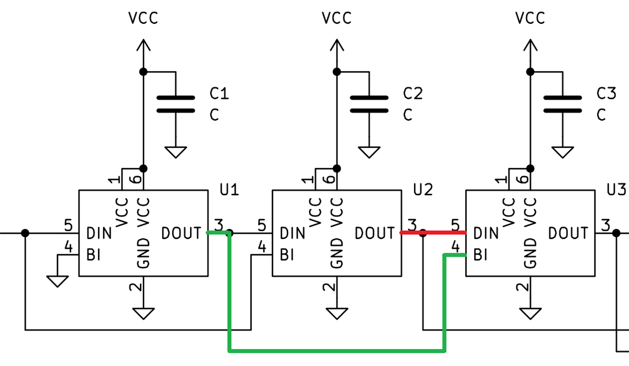
Wire highlighted by red colour on schematics above is standard chaining of LEDs. Data Output (DOUT) of previous LED is connected to Data Input (DIN) of next LED. Backup Input (BI) pin is connected to output of second previous LED. (I am not sure if Backup Pin is exact meaning of BI abbreviation, but it is my guess). If any of classic addressable failed, it stopped forwarding signal over daisy chain and all LEDs after it become unavailable to control. Purpose of BI pin is to mitigate it. It does not only target permanent failure like LED burning out, but it also targets intermittent failures, like when some LED lost power because of brownout and resets it’s engine in the middle of transfer. Purpose of BI pin is to mitigate faults like these. It obviously does not target faults like that some LED shorts power supply rails.
If middle LED on diagram above fails, previous LED still send data to BI pin of next LED, so while middle LED fails, left, right and rest of chain continues to operate. Chips in LEDs are smart and detect it. From LED point of view, it looks in a way, that every LED actually receive data on BI pin first. But the data received are actually intended to be used by previous LED, so LED ignore them. After 48-bit for LEDs is received, LED expect that it receives it’s own 48-bit while receiving the same 48-bits on DIN pin with short delay caused by forwarder in previous LED. If it does not happen, it processes data from BI pin because it technically the same data are transmitted here. BI pins work even when multiple LEDs on strip are broken. There just must not be 2 consecutive LEDs broken. If there are 2 consecutive LEDs broken, next LED do not receive signal from DIN nor BI (because both come from broken LEDs) and rest of the chain stop operating as well.
Let’s test in practice. If you read my previous blog, you may know that I partially intentionally and partially unintentionally omitted two LEDs on my testing PCB.
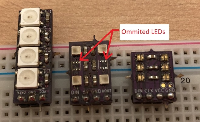
These missing LED actually behave like “broken” LEDs. There is nothing what would forward signal to next pin. But because of BI pins, this strip should work. Let’s test it.
Since signalling of these 48-bit LED is compatible with 24-bit, there were very little updates to the firmware. In fact, any firmware which works with 24-bit LEDs work with these 48-bit ones, but you need to set 2 LEDs for every 1 LED on bus and it needs tricky encoding of R, G, and B channels of these 2 virtual LEDs. I modified API of my library in this way. Originally, I had following functions
void LEDS_Init();
void LEDS_SetLed(size_t index, uint8_t r, uint8_t g, uint8_t b);
void LEDS_Transmit();
I renamed SetLed to SetLed24 and added SetLed48:
void LEDS_SetLed48(size_t index, uint8_t rI, uint16_t rPWM, uint8_t gI, uint16_t gPWM, uint8_t bI, uint16_t bPWM);
This function takes rI, rPWM, gI, gPWM, bI, and bPWM which corresponds to current and PWM values for each of RGB channels. It recodes them and set actually two slots in internal buffer. For this reason, when 48-bit function is used, it should be called with index multiplied by two because every LED occupies two entries in that internal buffer. While this design is strange at the first look, I will utilize it in later experiments when I will try control both 24-bit and 48-bit types of LED on single chain.
Example usage is something like:
LEDS_Init();
int iGain = 0;
LEDS_SetLed48(0, iGain, 50, iGain, 0, iGain, 0);
LEDS_SetLed48(2, iGain, 0, iGain, 50, iGain, 0);
LEDS_SetLed48(4, iGain, 0, iGain, 0, iGain, 50);
LEDS_SetLed48(6, iGain, 50, iGain, 50, iGain, 0);
LEDS_SetLed48(8, iGain, 0, iGain, 50, iGain, 50);
LEDS_SetLed48(10, iGain, 50, iGain, 0, iGain, 50);
LEDS_Transmit();
Code above. Set 6 LEDs on strip to following colours: red, green, blue, yellow, cyan, pink. I set values to 50 instead of full range, so it does not blow up my eyes. It also look slightly better on photos. So, let’s upload this to microcontroller, connect it and see what happen:
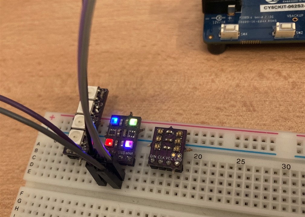
It works. Even with LEDs missing. As you can see stripe is not shift if failure like broken LED happen. Second colour (green) and fifth colour (cyan) are missing because LEDs which should light them are “broken” but rest of the strip work and colours stay at their position exactly as defined in source code.
I cheated a little in this experiment. It actually does not work reliably because I am controlling these LEDs by 3.3V microcontroller. And actually, these LEDs require at least 4.2V to operate. I actually power them from 5V rail of development kit which is fine, but control signal is only 3.3V which is slightly below threshold of digital logic in LEDs. Datasheet specify that your signal must be higher than 0.7 * VCC to be reliably classified as logical 1. In case of 5V supply 0.7 * 5 is 3.5V, so 3.3V is not enough. My favourite trick on this issue, is connecting my cheap Chinese logic analyser. It is connected to wires which go to left side on photo. Also works with scope probes from Multicomp Pro oscilloscopes. Not exactly sure how small additional capacitance or whatever make this working, but it typically works for me in these cases.
Propper solution is use voltage level shifter. Sponsored challengers received one. I have it as well in my drawer. I was lazy to use it and connect bunch of wires to it since I know this simpler cheat  Another possible solution/workaround is to lower voltage supply. If you change 5V to let’s say 4.5V. VCC * 0,7 is now 3,15V and this is lower than 3.3V control signal. Another cheaty solution is to violate 4.2V minimum voltage and power them just by 3.3V. I tested it. They seem working well. Did not test running all possible codes and did not test it long time under various temperature conditions, but it may be easy workaround for development time.
So that’s it for today. Outcome is that my soldering was successful. The only two faults on board are intentionally missed LEDs and strip works even without them. Tomorrow I will look at the last type of LEDs which I did not test yet. And actually, they are the smallest one, so highest change of soldering issue. But let’s see. They also use different protocol, so I will need to rewrite testing firmware once more.
Next forum post: Misaz’s WL-ICLED experiments: Mysterious End Frame
