


Hello everyone. I continue working on next experiment, but I found something which is strange or at least somehow interesting, and decided to dedicate blog to it.
I was implementing last protocol. It is two wire protocol supported by 1311610030140 LEDs. This protocol is interesting because, it does not require exact timing. Other LEDs require you to emit LED signal at specific frequency, with some tolerance, but not big tolerance. These LEDs are different. They have separate pin for data and clock and allow transferring data at any speed up to about 33 MHz. It has several benefits. First of all, you can clock your MCU at any speed you want. In case of classic LEDs, you need to adjust clocking system of MCU which typically place constraints of MCU clocking and can limit you if your design contains more timing sensitive parts. Other benefit is that you can get much higher data transfer, which may allow you to make much longer strips while maintaining same refresh frequency.
Such protocol is described in datasheet using following diagram (and table describing requirements for T parameters mentioned in diagram):
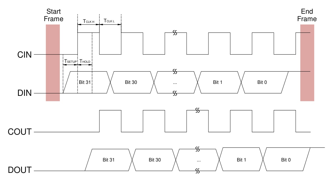
This diagram is somehow confusing. There are several parts more or less confusing. Sadly, Würth datasheet has no explanation. It actually contains absolutely no texts except tables, diagrams, graphs, etc. Well, there are two technical sentences as a note on the bottom of pages. The only other texts here are some legal disclaimers. I always expect datasheet to be comprehensive source of truth, but this one slightly weak. The most confusing part to me is “End Frame” section. It is slightly better explained on later diagram in datasheet including description of somehow similar “Start Frame”:
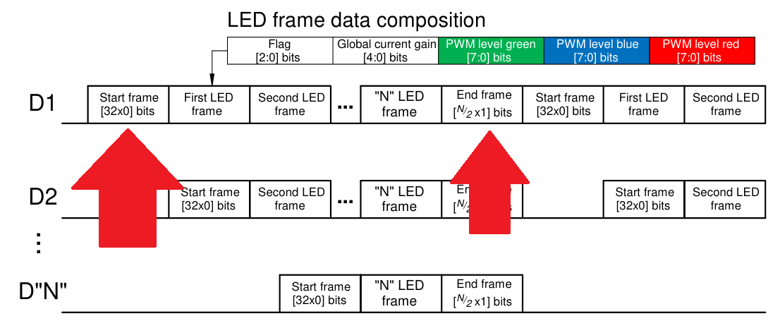
Start frame is easy. But I do not understand purpose of end frame. It says that it should generate one bits and the number of bits is equal to N/2 where N is strip length. First interesting thing is that according to this formula, it can end up with number of bits which is not even divisible by 8. It makes very hard time when implementing driver using SPI peripheral, because very few peripherals support configurable data width with all possible options less than 8. But you can design your software in a way that strip is always multiple of 16, then you can just add bytes to end. Strip do not know how long it really is, so you pick lowest higher multiple of 16. For 100 LEDs, you can make it 112 LED long on software layer. Another interesting part is division by two. There is not written anywhere if it is intended to round down or up, but Würth official library says up in comment.
I implemented it and it did not work. For some reason, only first LED light up. For some time, I consider soldering fault on my side, but I tried to play with this strange part more before resoldering and make it somehow working.
N/2 Stop Bits
One of my theories was that purpose of this section (no matter how crazy it’s definition is) is for synchronizing LED to start emitting new colour at the same time. If chips in LEDs have counter, they can count how many data were transferred before reaching this end frame and then start emitting new colour all at the same time. They do not need to compensate length of data transfer, because they actually receive end of frame bits all at the same time as highlighted on diagram in Würth datasheet. They only need to know when it should happen and for this reason end of frame could be useful to indicate it.
32 Stop Bits
My other theory is that it is used for compatibility with some other LEDs. Only LEDs with similar interface I know are APA102 which seems deprecated and very hard to acquire to me, but their datasheet is searchable. Their protocol is almost identical, including format of start frame, but end frame is not defined in such horrible way. In case of APA102, end frame is defined as sending 32 x one bit, basically the same as start frame, just ones instead of zero. I implemented emission of exactly 32 high bits, instead of N/2 high bits and Würth LEDs accepted it. But there was strange behaviour that when LED was not power-cycled since previous experiment, they started to emit colours as expected, except exactly second LED which turned off. This seem weird to me because 32 ones are valid command for LEDs for white at full brightness. After I power cycled board to reset all chips, even with 32-bit stop bits they no longer accepted colours and stuck in state, where only first LED work, exactly as in previous experiment.
0 Stop Bits
After such experiments, I looked how professionals do that. I looked how Würth implemented it in their official library. And to my surprise, they have some macros to counting stop bits, they allocate space in buffer for that, but they do not set them to ones. And especially, not to N/2 ones. They define buffer in this way:
static uint8_t DATABuf[ICLED_BYTESTOTAL] = {true};
I think they thought, that when defined in this way, C/C++ runtime will initialize all values to all ones. They actually reset Start bits to zero before sending data. But true is not 0xFF, but 0x01. Second, C/C++ standard says (using very simplified words), that if array initializer has less data, then array size, remaining part of array is zero initialized.
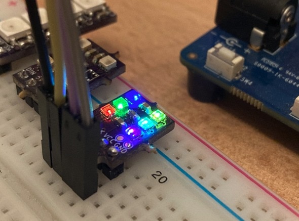
So, they actually send zero bits as stop bits. I tried experiment with it slightly differently and try send no bits at all. It started working, I have seen right colours on all my 6 LEDs.
First refresh, only first LED works
One issue which remains (and it was issue in all previous cases) is that on power up and first data transmission, only first LED works for some reason. At second refresh, all LEDs updates and start working. Maybe my signalling is still wrong. In datasheet there is several more confusions like that clock and data signals at the beginning of diagram are low, but at the end, they are high and there is no explanation when should MCU switch from high back to low. This basically define CPOL param when SPI peripheral is used to generate signal. Würth use CPOL=0 in their library. Also, it is not clear how 3-bit command type interfere with start and stop bits and if some detection of transfer phase is implemented using these.
Floating (High-Z) pins at powerup
One issue with (not only these) LEDs is that MCU pin is typically floating in time between power up and time when MCU initializes GPIO setting. I added external pull down to eliminate issues caused by this, but it has no impact on issue with only one LED working on first refresh cycle.
Searching Internet for Truth about End Frame
This is obviously lot of unexplained magic. So, I tried searching for LED which I think 1311610030140 are intended to be compatible with. I searched for APA102 and found library implemented by Pololu. It contains 20 lines long comment explaining real purpose of end frame. Simply rephrased, LEDs behave differently than I thought. Logic on clock signal is more dumb than I thought. Every LED just negate clock input signal and pass negated one to next one. This cause shift of half period. This minor clock shift LEDs use for data forwarding. Logic in controller wait for it’s 32-bit of data. Every (not only first one) LED receive clock almost immediately when data transmission begins. Clock is available to all LEDs immediately using chain of inverters. Only data transmission is delayed. Actually, while first LED receiving it’s data, second LED still receives zero bits. It seems that start frame can be arbitrarily long. My understanding is that LED identifies it’s own data by observing first high bit after long (at least 32-bit long) sequence of zeros. At that time, it still propagates zeros on output data line. After it receives it’s own complete 32-bit frame, it starts propagating data to next LED. I deduced this by observing how signal outputted from 6th LED looks like. I exposed this signal on test pads on my PCBs. It would be better to evaluate single led individually but unluckily; I made PCB with 6 LEDs.
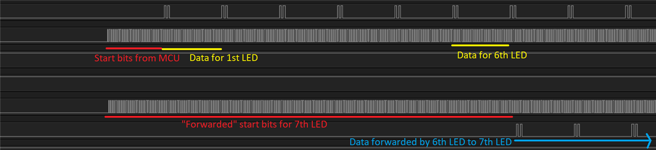
Data are shifted by half of the cycle because output clock is inverted input clock. But because clock is ultimately generated by MCU and data rate is lowered half a cycle on each LED, if MCU send 0 stop bits like I did, last LED will miss some clock cycles. For this reason, MCU need to generate at least N dummy clock edges or in other words N/2 full clock cycles, which are used just to propagate final bits which will be otherwise lost because of propagation delay on chain.
Why 0 Stop Bits worked?
It most probably did no work and worked only just by accident. It most probably explains why it did not work at first run. I still think Würth add some logic to determine validity of chain and synchronized colour switch to happen at the same time on whole chain or something like that. When I send zero stop bits, LED signal was likely incomplete and for this reason LEDs did not switched colours at first run. But when second refresh begin, it started with start signal which generated cycles which were missing in first run and at that point LEDs started emitting right colours. But I suspect that it was actually data from previous run. From my experiments it seems that LEDs has absolutely no timeout logic and end of previous transfer can interfere with start of next transfer. And this I consider quite problematic. Do you remember the confusing part that Würth’s diagram start at logical low level and ends with high level without explaining when and how should MCU switch between them in between transfers? I made some experiments and behaviour actually differ if last transmitted bit is low or high. I tried change end frame to be 0xFE instead of 0xFF and it actually behave differently. It definitely needs more investigations to understand what’s exactly going there.
Conclusion
While I explained some mysteries, I still did not manage to make it fully reliable. I will continue experimenting with it, but for now I wasted much more time than expected. It would be really nice If European based chip company produce normal reasonably detailed datasheet explaining chip behaviour and implemented features. Making even datasheet detail level compatible with Chinese is not good idea and cost me lot of time. Because time is running low, I will switch back to classic single LEDs for a while and continue with experiments according to original plan to be able to complete final project in time. While this forum post was quite longer, next time will be much shorter because I already concluded experiment and it went well. Btw, one lesson from today is that writing forum post/blog for element14 can serve as debugging duck. Thank you for attention. See you in next forum post.
Next forum post in my series: Misaz’s WL-ICLED experiments: Combining LEDs of multiple types