


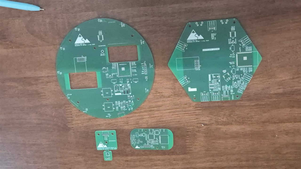
With things i learnt from my mistakes and experimentation of test pcb documented here i ventured into designing the 3 pcbs needed to complete the project. I started feeling if i bit more than i could chew, but commitment is a commitment, lets get it done
Tile-able Wall Hex mounted Design
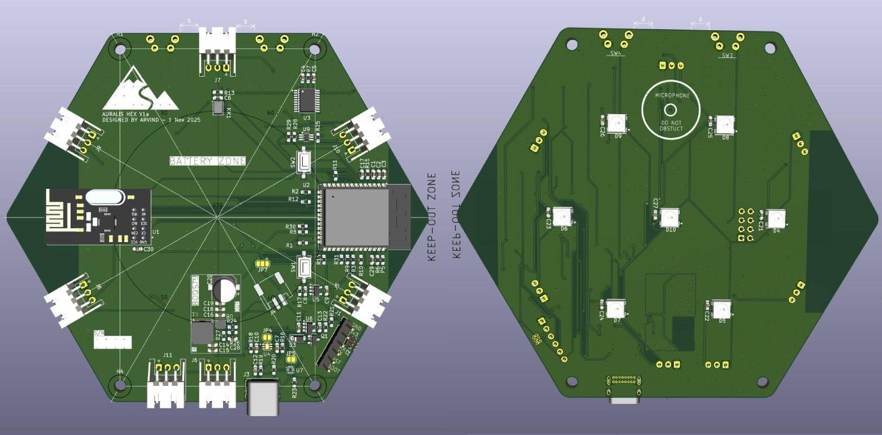
This device can be daisy-chained for grabbing attention in large halls or rooms etc. I got the inspiration from Nano Leaf product. The components are exactly as in the test pcb except for the PCB. I decided to put the LEDs on one side and the rest of the components on the other. I wanted to arrange the LED's in a way to light up the acrylic and diffuser sheet evenly at-least everywhere except the edges. So Math comes to my rescue. Let us say the gap between two LED is "s" and the distance between the LED and the plane where the diffuser sheet will be is "d", With a FOV of 120degree, a bit of trigonometry will tell me that it should be s=3.46*d. But at 120 degree edge, the intensity is going to be only 50% therefore i should reduce the distance s to make it even. i've opted for s=1.15d. This is an empirical formula from experimentation. So I proceeded with s=30mm. I also added 3 Pin connector on each side of the hexagonal PCB so that it can be tiled using wires.
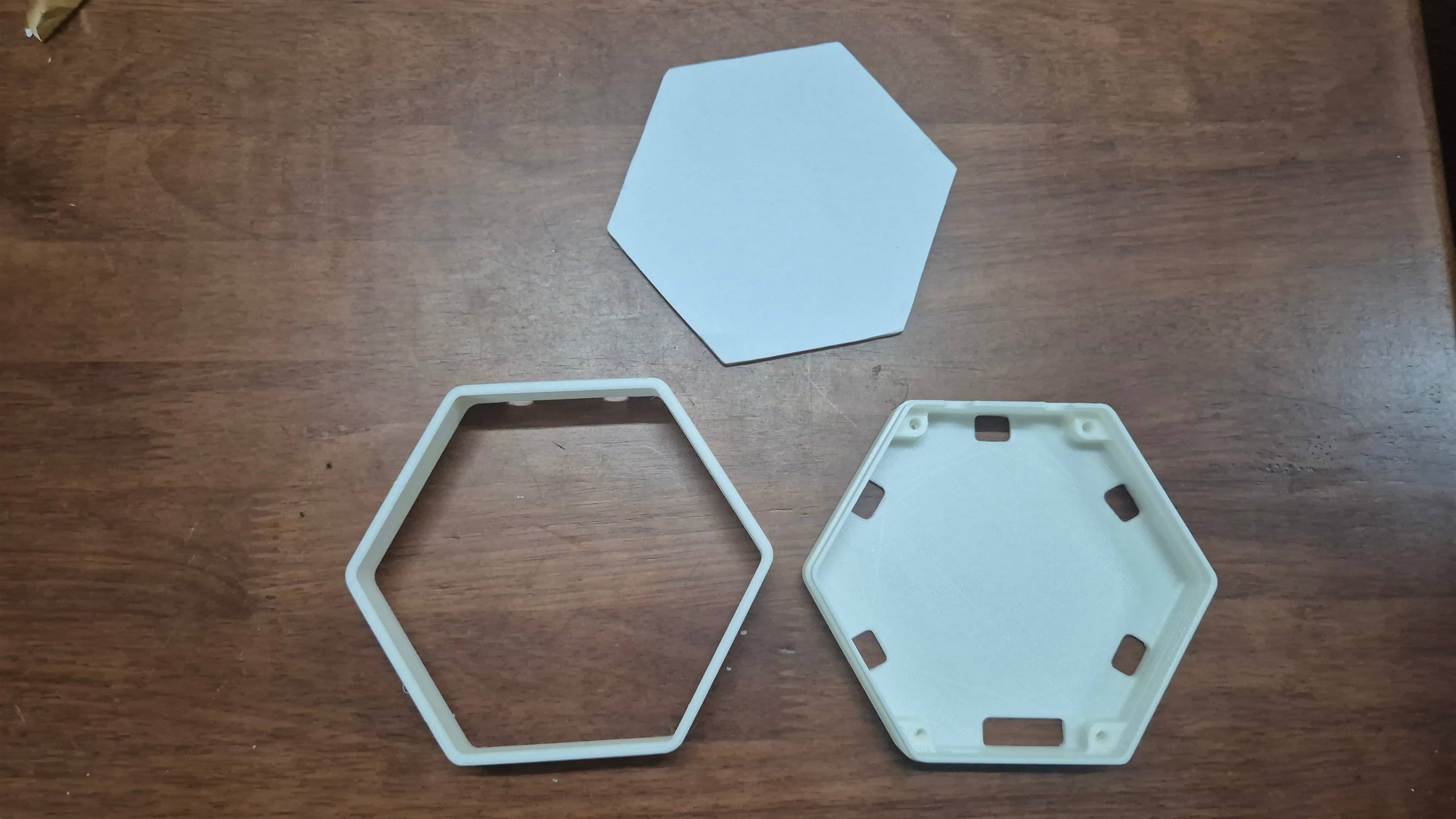
Based on this i designed a two piece casing. I used white PLA for the casing, and 3mm acrylic sheet with diffusion sheet pasted on top as the front part.
Wall Mounted Halo Design
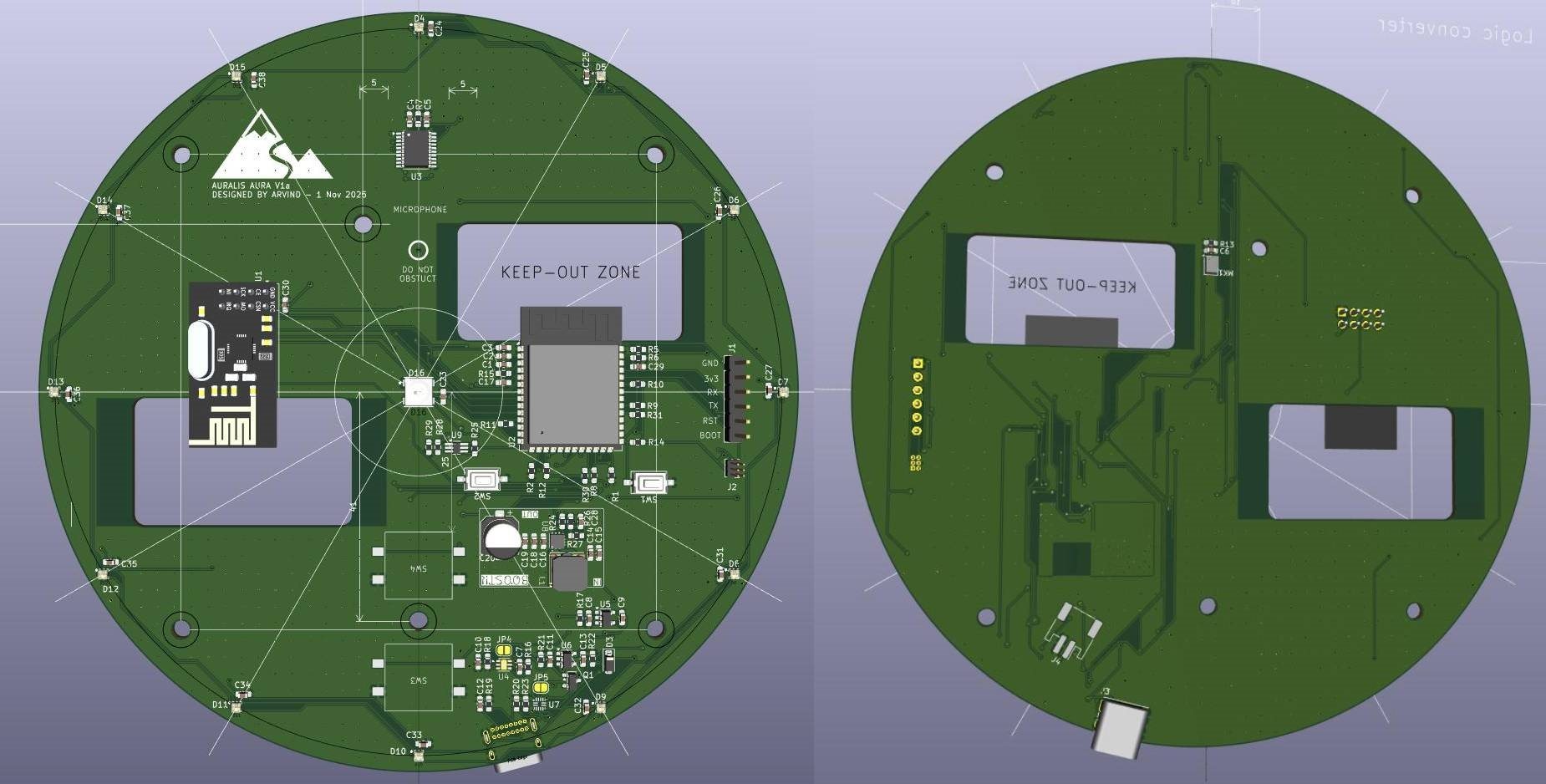
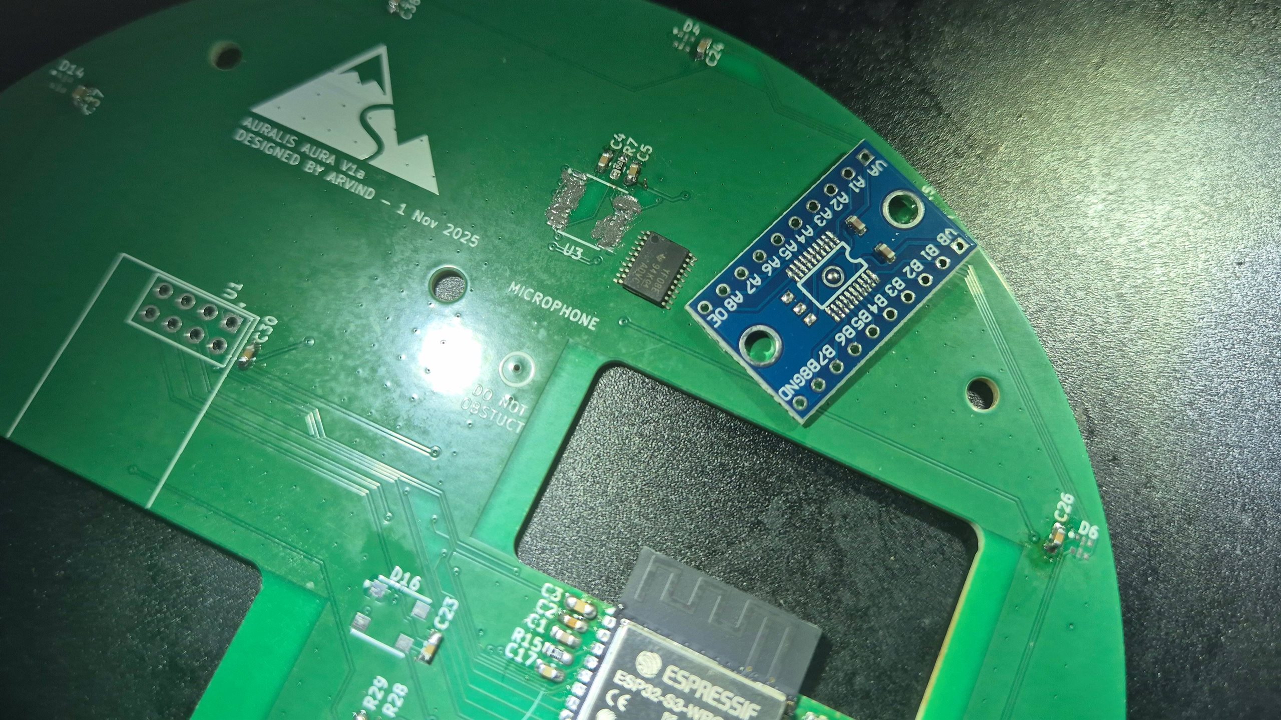
The largest PCB with LED around the edges to create a halo effect turned out to be a challenge to place my wireless components, ESP32-S3 and NRF24. Usually i place it on the edge as far as away from each other, but in this case, the LED's come in the way, so i had to innovate. Perusing the best practices for wireless modules, i made a cutout and a no-copper zone atleast 20mm around the antenna. The placement almost every component was on the same side. Then i found, i couldnt put the USB port exactly on the bottom. I had only the Through hole version and since the LED was on top, i had to offset the USB-C towards the side. I hope it won't trigger anyone.
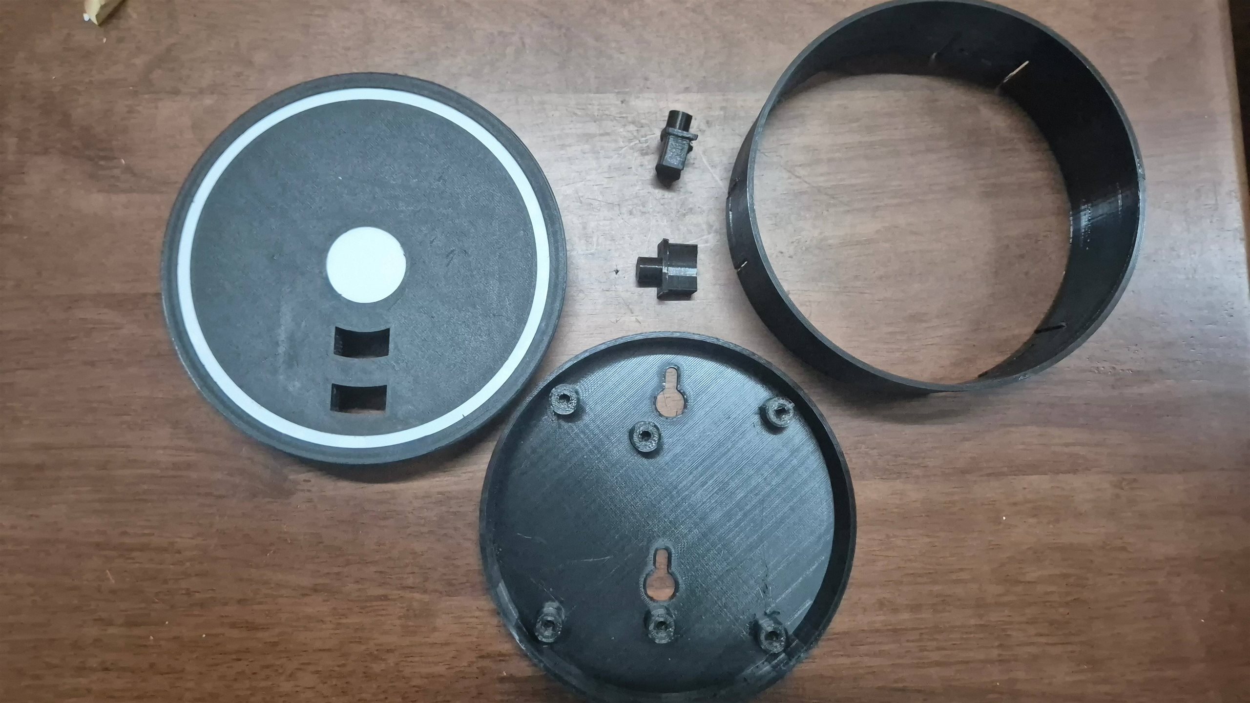
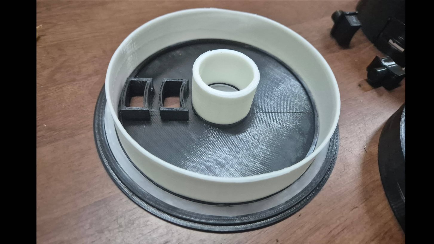
The casing was also extensive for this.I tried to keep it simple but I thought that if the LED's light is not channeled towards the halo then it is gonna be losing intensity. so, i 3D printed white cylinders which will help bounce back some of the light towards the halo ring. Rest of the case i wanted to be in Black to achieve maximum contrast. The Laser cut acrylic sheet was quite fragile and i had to be extra careful, as I had to work with minimum materials available on hand and i couldn't to afford (in time) to make extras. I managed to install it without any difficulty and it turned out quite nice and robust once the super glue dried. The buttons took me few iterations to get the smoothness right.
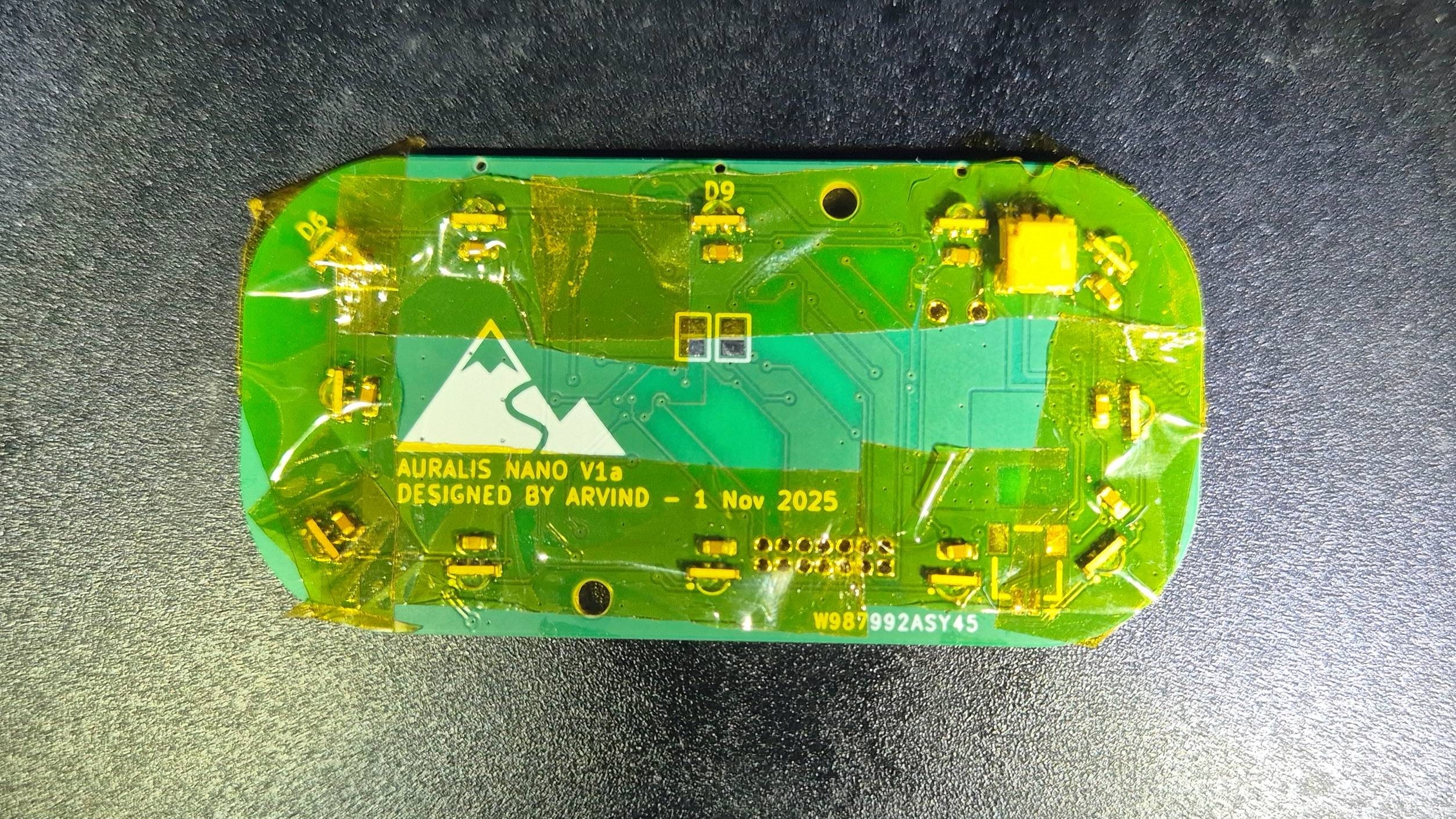
Hand Held Device PCB
This had to be as small as possible, I thought of a while to use a 4 Layer board board, but decided against it as time was running short. One thing that bugged me is that the Buck booster's TPS6123 required me to have a large space for the Power Ground and the inductors. Squeezing them as efficiently as possible in the wall mounted devices required at-least 22mmx12mm of space, not to mention that the inductor was quite high, So i dived into element14, to choose the smallest yet cheapest buck booster and i settled on Renesas ISL9113ER7Z-T which was only half a dollar and with this i was able to get the size down to 8mmx7mm. Soldering this was also a breeze. I also went for Wurth's Side Tactile switch WS-TASU for the switch. For the NRF24, i did not want to put my own Antenna, again just to save time, so i got myself an SMD version of the NRF24 Module. I arranged the sideways Wurth's LED 1313210530000 (12 nos) on the bottom layer in a ring fashion 1312121320437and the three 1312121320437 on top, considering the FOV for as much as uniform lighting as possible. I even opted for TXS0104E instead of TXS0108E to save space. It has only 4 channels instead of 8.
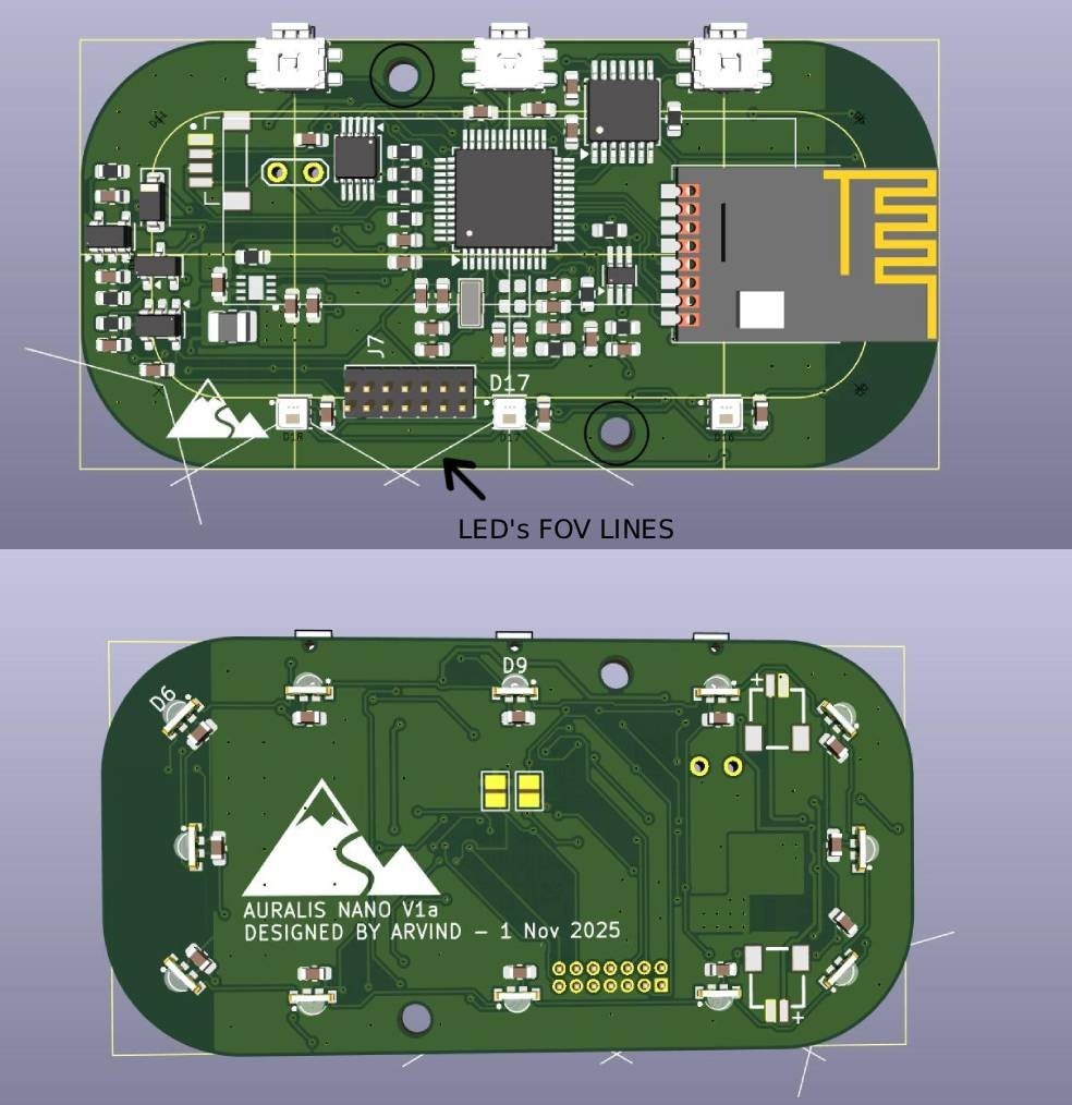
Unlike the previous devices, low power is one of the thing i was looking for and so it is STM32L051 as the main CPU here along with DRV2605L for haptics control along with a 128x32 pixel monochromatic OLED Panel.
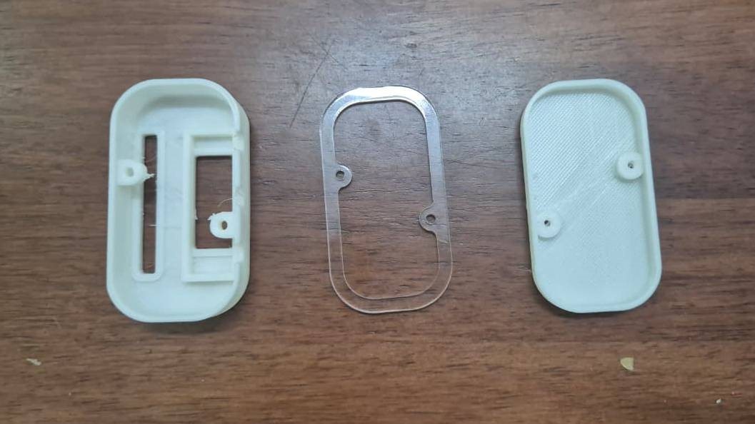
The casing was designed as a 3 part design. One cut from transparent acrylic as a light pipe for the light strip, and rest made from White PLA.
4th PCB - Hand held device charger
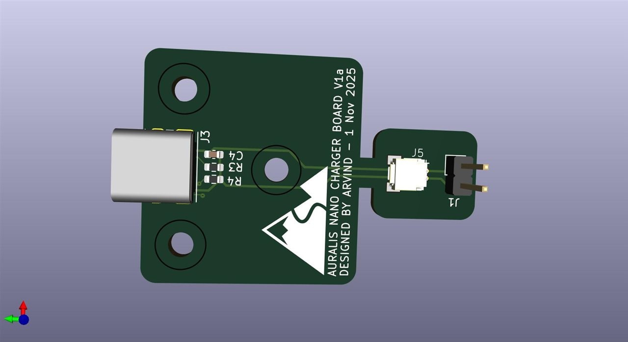
Again, to squeeze more space, i opted not to use the USB-C and bought two pin pogo pin connector.I designed the PCB in such a way that i can use one copy of PCB as desktop dock connected to USB-C and i can use another copy, break it at the neck as a daughter board with the mating pogo pin to be connected to the hand-held device via JST-SHR series connector. You won't believe it that i had the connectors lying around in some box which i have not touched for around 8 years.
PCB Manufacturing
I had very less time to get this manufactured and this is where things got fun deciding whom to go with. My Fav PCB way is in China, i have couple of local manufacturers. I opted for PCBWay mainly because they get it manufactured within 18:00(UTC+7:30) on day 1 if i submit the order by 08:00 on day 0. Then only factor was Fedex and Customs, again something I've experienced it well in the past. in Total, 2 days for mfg and 6 for shipping and custom's I've got it in my hand. This time while ordered, i noticed a new option, not sure if was there before, but there is an option where you can opt-in for free upgrade to ENIG Finish. It is not guaranteed but I wish i had it got it.
TXS0108E Issues
This I've noticed in the Test PCB that twice i popped the magic smoke of TXS0108E. I spent almost half a day and it turned out that the Enable PIN when low keeps the pin in High Impedance state and should be enabled only if the high side VCC power is stabilized if not then it can damage the chip. So for all the three PCB's i had to connect a microcontroller pin to turn it on/off. In the hand held device, i forgot to attach it to a micro-controller and so I had to adjust it with a jumper wire. Has anyone faced TXS0108E issue?
Soldering
The Soldering of Hex PCB was easy, as this part has the largest LED with the minimum number of pins.
Halo PCB Soldering was hard as it couldn't be accommodated in any of the PCB holder i or my university had. My decision to have every component one side turned out to be good one after all. When i tried assembling it i realized i forgot to put an hole for the USB-C port. Oh well, fixed it by some flush cutters.
The soldering of hand held device took time as i had to omit all component reference silkscreen to cram it all into a small PCB but it was fun working on such closely spaced components. I felt so happy that i had invested in these Precision Straight Tweezers - Rhino SW-11 from adafruit in the past . One thing i have to let you know, it is not immune from bending from dropping as adafruit claims in the videos.
Testing the PCB's
I decided only to test the Microelectronic, Boost converter, Battery charging, LED control along with level translator. Only a video can give proper justice to the result
Now off to the project


