


Welcome to installment number 19 of the Design Challenge Project Summary series here at Element14. For those of you who are new to my content, in this series I will pick a single Design Challenge project from the current challenge, and write a short summary of the project to date. Over the course of each challenge, I try to revisit each project at least once, and I am sure that some project summaries will get more than one update if the project is updated frequently. Some project creators like to keep their own project summary going, and this series is not meant to overshadow those post, but to highlight each project from an outsider's perspective.
The subject of this installment is project ELapShelf by Scott Coppersmith (rsc). The goal of this project is to develop a motorized articulating table top that is easily maneuverable by someone who might be constrained to a bed or wheelchair. The project will feature the NXP FRDM-KV31FRDM-KV31 development board and FRDM-MC-LVPMSMFRDM-MC-LVPMSM motor control board.
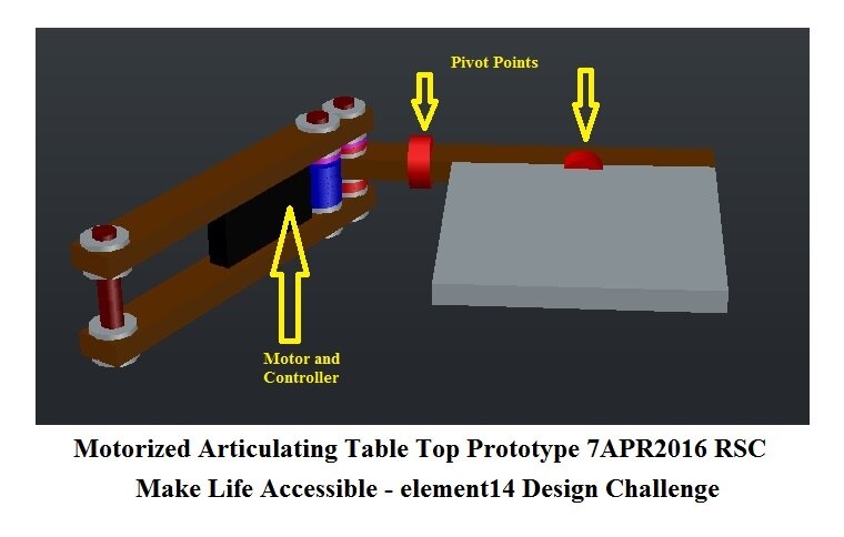
Scott’s first post gave us a brief introduction to the project. He says that his inspiration came from being confined to his bed for a few days due to a knee injury, and how unproductive not having a proper articulating work surface is when laying in a bed. As you can see from the image above, the tabletop will feature two pivot points, as well as an actuating arm, but it is unclear as to if the pivot points will feature separate motor control, just rotate mechanically.
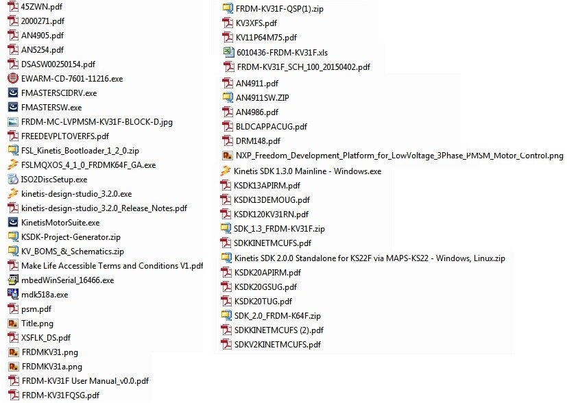
In his second update post (https://www.element14.com/community/community/design-challenges/makelifeaccessible/blog/2016/04/13/make-life-accessible-design-challenge-software-and-documentation), Scott quickly talked about the software toolchain options available for this project, and mentions that he has used at least one of the compilers in a previous project. After some careful thought, Scott decided to use the Kinetis Design Studio for this project, along with the Kinetis Software Development Kit, and he finished off the post with a link to some helpful tutorial videos for the KSDK.
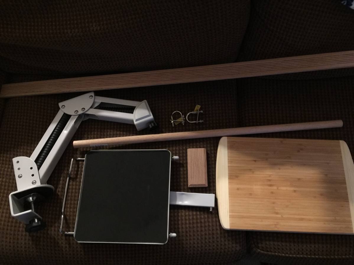
Post three and four were both very brief, with post three detailing some issues that have arisen with the motor that is supplied in the challengers kit. Scott says that the motor is just too fast for his application, and that a gear reduced stepper motor would be a better choice. He also mentions that the motors weight is a little too much for his original design plans, and he will be moving it further back on the arm to compensate for this. Post four comprised of a brief explanation of the parts that Scott has been gathering for the project, including an old CRT Monitor stand, some lumber, and what appears to be a bamboo cutting board that will serve as the table's surface.
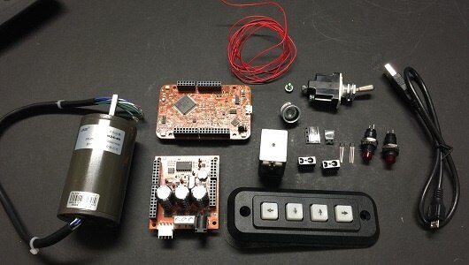
Update number five was another brief posting, and simply showcased an image of the parts that had recently arrived in the challenger kit.
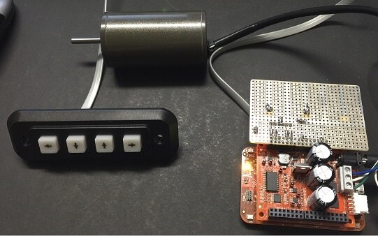
The project took a huge leap forward on May 13th, when Scott posted updated number six which detailed his attempts to get the motor controller up and running with the KSDK. As you can see in the image above, a small prototyping PCB was used to create a very simple circuit that allowed the motor to be easily connected to the switches that came with the challenger kit. The post contains a small schematic of the circuit, and code needed to control the motor’s speed which is done via a demo program with a PORTC interrupt routine that decodes the buttons and changes the motor’s speed.
The seventh update included some information on the mechanical assembly of the project. To be more specific, gears. Scott found a nice set of gears in an old printer, and had to create an adaptor that would allow them to mate to the shaft of the motor that came with the NXP kit. As you can see in the image above, this adapter worked out quite nice, and allowed Scott to get the mechanical assembly of this portion of the project finished.
Update: 27 June 2016

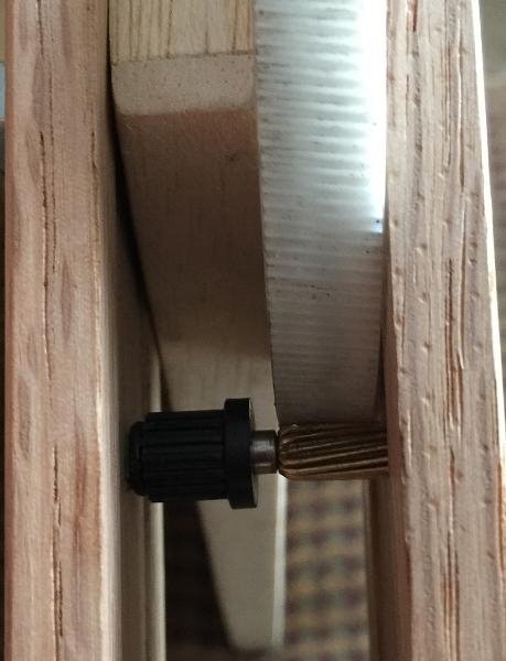
The project arrived at its eighth update on June 13th, and discovered that Scott was having some issues with too much friction being applied on the gear shafts due to the wood he used not being a good bearing surface. To fix this he said that he plans on adding some bearings to the shaft ends in a future update. Despite the friction issues, the project is moving forward nicely, and as you can see from the image above, everything is meshing together quite well. I especially like the use of the timing belts over a gear reduction box.
In the project’s ninth update, Scott showed off an accessory he is building for the project as sort of a bonus addition. Using a NXP PCF8883 Capacitive touch proximity switch IC that was included in the challenger kit, Scott plans on building a touch sensitive reading lamp to the lap shelf.
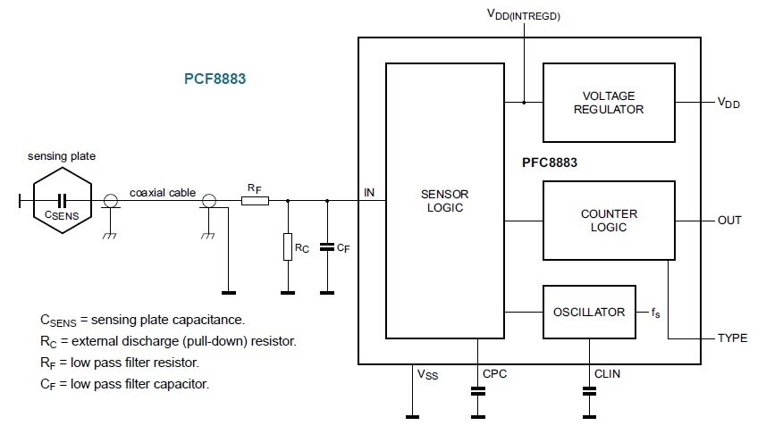
The basic circuit was taken from the NXP PCF8883 data sheet and can be seen above. “I used a SparkFun SOIC to DIP 8 pin adapter PCB along with a few Rs and Cs to wire up the touch control,” Scott said. “I don't need to run the switch through the FRDM-KV31 board, but that might change later.”
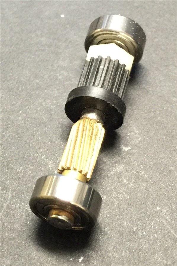
Update ten followed just a few days later, and Scott detailed how he worked to reduce the friction that was causing the gear shaft bearings to bind and stall the Linx motor. In the image above you can see the two ABEC5 bearings that were repurposed from an old set of roller blades. “One side of the shaft had to be ground down for the bearing ID, and the other side of the shaft had to be built up using slices of telescoping brass tubing to fit the bearing ID. I soldered the brass together at the end so It can't come apart,” he said. “To grind down the large side, I put the shaft in a drill and spun it next to the grinding wheel to keep the shaft concentric. All-in-all, the bearing "upgrade" took about 6 hours and I now have an alignment problem to work out before I can get back to coding.“
Update: 9 July 2016
Update eleven was posted about a week left before the challenge deadline, and Scott revealed that he had decided to scrap the old oak frame that was serving as a mount for the gear train, opting for a more sturdy, thicker oak frame. “This added some needed stiffness and let me embed the shaft bearings deeper into the wood. The system is still a bit wobbly,but it's working,” he said.
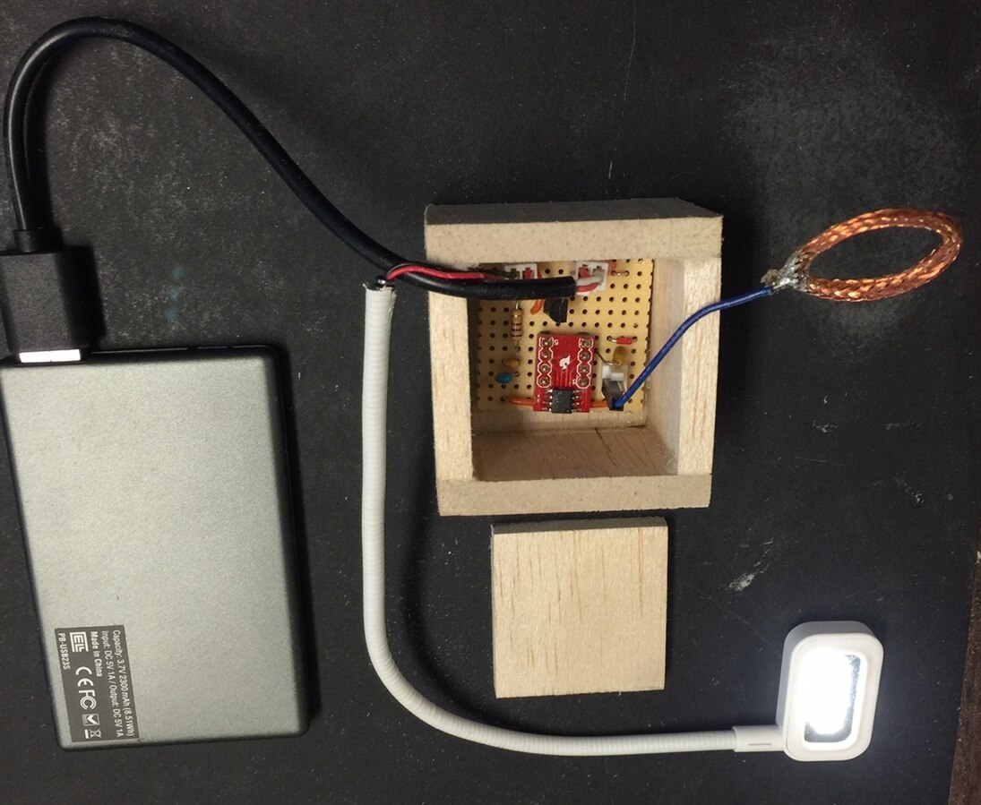
On the 28th of June, Scott posted his second to last update, and detailed his progress on the touch-sensitive lamp that he has developed for the elap shelf. After crafting a small balsa wood box to house the electronics, a small 2300mAh USB power bank was repurposed to power the LED light.
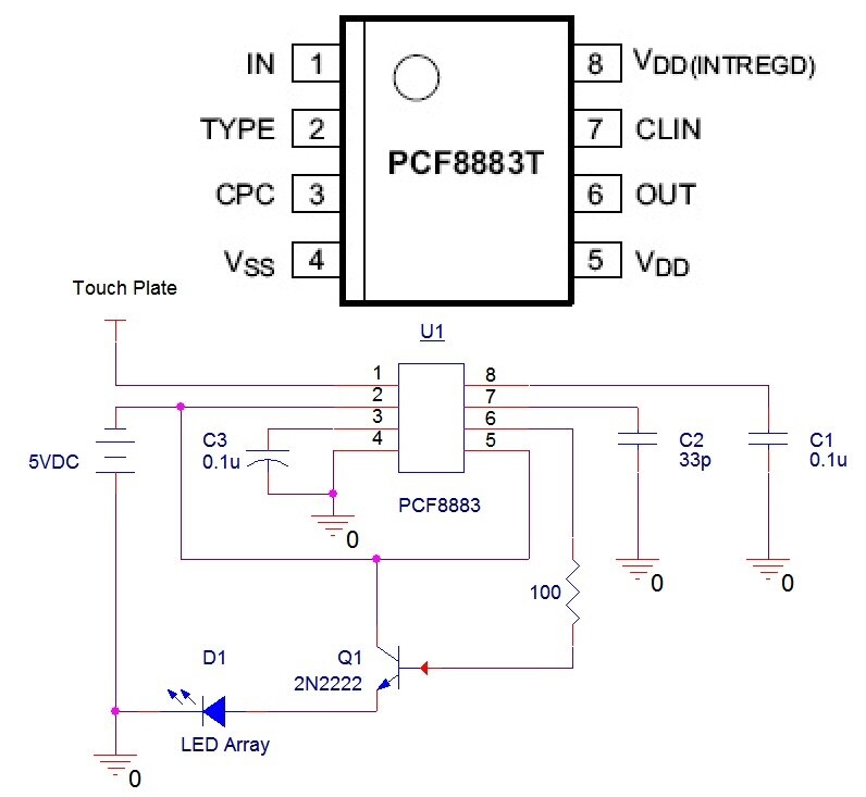
The LED lamp is controlled using a NXP PCF8883NXP PCF8883 Capacitive touch proximity switch IC that was included in the Make Life Accessible kit, and as you can see from the schematic above, it's quite a simple circuit to build. The addition of a light source to this table is definitely a nice touch, and should provide the end user with some added value.
The final update came on July 3rd with Scott posting an image of the elap shelf in is final configuration, as well as a demo video of the shelf in action. This project turned out exceptionally well, and I am very impressed with the rate at which this project received updates. I wish Scott the best of luck in the judging process!
That is going to wrap up my project summary coverage of project ELapShelf. Tune in next week for another Design Challenge Project Summary here at Element14. Until then, Hack The World, and Make Awesome!