


This is my third blog post in a series that cover my experience going through the training courses of the Path to Programmable 3 challenge. The first two blog posts, Blog1 and Blog2, have covered the beginning of participating in this challenge and my learning experience from going through the SW Lab 0 to Lab 4. Now I am continuing with Labs 5 – 11.
Lab 5 was quite exciting because I have first connected the MiniZed board to the computer. The Zynq SoC FPGA does not retain the programming during board power down, so every time we power up the board the programming file is loaded from a Flash memory into the FPGA. While this is the standard practice for a product functionality, during the design phase and experimenting the FPGA can be programmed directly from Xilinx tools Vitis or Vivado. The FPGA will stay programmed until we power down the board or until we reprogram it from the Vitis or Vivado. So the MiniZed board can program the FPGA either from a flash memory chip on the board or directly from the computer through a JTAG interface. There is a switch on the MiniZed board that sets the programming either from Flash or JTAG:

So, in my case I have setup the switch to the “J” JTAG option, and I have used the USB-JTAG/UART port for communicating with the computer. There is also a “traditional” JTAG connector on the board that can be used with an external JTAG programmer.
Next, I have created a folder for lab 5 and I have followed the lab instructions to import the project into lab 5 folder, to build the project, and to run the “test Peripherals” application in debug mode:

The program was then loaded into the FPGA and the immediate result that I have noticed was the blue LED turning ON:

The rest of the steps in Lab 5 went smoothly with no issues. I could see the test peripheral test results all passing. The next part has explored the debug commands: inserting breakpoints, pausing the debugger, and pressing resume to continue the test. That was pretty much all for Lab 5. I enjoyed this lab as it was closer to a ”hands-on” type of activity.
Lab 6 thought me how to generate a first stage bootloader application, FSBL. While this is an important part of a product development, to me this lab was primarily only following the instructions and watching how everything “falls into place” in the experiment. Not much excitement for me during this lab, but again I want to emphasize that what we covered in Lab 6 is quite important for a project. Lab 7 has built up on Lab 6 by teaching me how to create a boot image and how to boot from QSPI. Creating the QSPI boot image went smoothly by just following the instructions. Same as in Lab 6, everything just “magically” felt into place just by following the instructions, and in the end, I was able to boot the MiniZed board and to see the results in the terminal. Lab 8 was more like a “hose keeping” activity that is really useful, but it does not have any excitement in doing it. This is important information that if it works it just passes “unobserved” but if it doesn’t work it becomes very “visible” and has a big impact in slowing down the product development. For me, I just followed the instructions to learn how to archive a project in a zip format and how to import the archived project into a workspace. One important thing I learned is that if I don’t archive the project using the Vitis function and I only copy or backup the project directory then later the imported/copied project is not guaranteed to work correctly.
Lab 9 has covered the interrupt functions. This is a useful concept since most of the projects have to use interrupts. So, part of this lab I learned how to use the interrupt service routine, ISR, to call a subroutine in the code when a hardware interrupt signal is received. This lab didn’t go so smoothly for me because some instruction steps didn’t match with my specific setup. One example is the reference to “LED_Dimmer_Poll” file that I couldn’t find and instead I have used the LED_Dimmer_with_int.

Another issue was that the LED that was supposed to adjust the brightness based on the number that I sent through the serial monitor did not adjust the brightness because I always got an error that the number that I entered is out of range:

Despite these “glitches” I still learned good knowledge from this lab as it exposed me to debugging the code (even though in the end I couldn’t figure out the actual problem).
Lab 10 went on smoothly without any issue. In lab 10 I learned how to create a blank project. I liked this topic since so far I always started with some existing project. So, I have followed the steps and in the I tested the application, and it worked as expected.
Lab 11 was the best out of all. I liked that I was exposed to a hands-on project that used connected an external sensor to the MiniZed board and the application has controlled the sensor and the MiniZed board to send the measured temperature and humidity values to a serial terminal on the computer.
The lab instructions pointed to use a HTU21D module, and the design challenge website pointed to using this sensor:

Since this sensor has not been included in the design challenge material, I went on eBay to buy one. However, while searching on eBay I have found a very inexpensive module that used the same HTU21D integrated circuit. I wasn’t sure if it will work or not so I looked at the datasheet of the module suggested on the design challenge website. The board is very simple having the SDA and SCL signals of the I2C interface connected directly to the edge mount connectors and having pull-up resistors to VDD. There was also a decoupling capacitor connected close to the integrated circuit power pins:
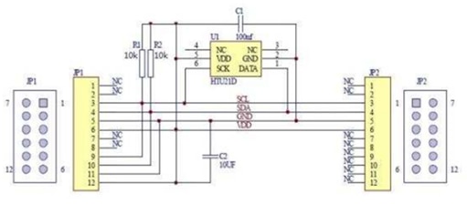
Next, I looked for the HTU21D integrated circuit datasheet, and in that datasheet, I have found an application example that looked very similar to the implementation on this board:

For the board I wanted to buy on eBay I didn’t have any documentation, so I have just examined the picture. From the PCB traces in the picture I could actually “reverse engineer” the schematic since it was so simple, and it looked identical to the same application example in the datasheet:

This observation gave me the confidence that the module that I found on eBay will work, so I went ahead and order it.
With this hardware setup I was then ready to go through Lab 11 steps. This is the lab that I have enjoyed the most.
Setting up the project in Vitis went smoothly after all the learning that I have done in Labs 1-10. Once the project and application were setup, I have connected the MiniZed board to the computer and I programmed the Zynq FPGA.

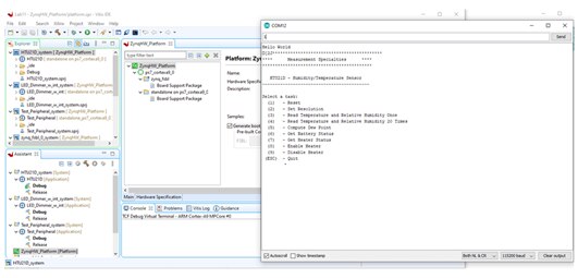
Then I opened a COM serial monitor window, I set it up for this board COM number, COM 12 in my case, and I could see that the communication with the HTU21 was successful:
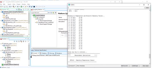
I have then sent the command “4”, which reads the temperature and humidity 20 times, and the serial monitor window has displayed the2 read values:

Then I wanted to make some environment changes so I can read a different humidity levels. So, I brought a wet sponge and I placed it in front of the HTU21 sensor:

The humidity values have increased from 33% to 61%:

Next I wanted to change the temperature, so I touched the HTU21 sensor with my finger and read another set of 20 values:

The temperature has increased from 24C to 32C:
This concludes my experience working on Lab 11 and the third blog post in this series. I will come back with additional blog posts as I advance more through the Path to Programmable 3 tutorials.
Until then, all best wishes to the readers and the rest of participants.
Cosmin

