


Introduction
Hi everyone! In this blog I will show you my final project of the "Path to Programmable III" challenge. This idea was inspired from the project published by Adam Taylor: Mini But Mighty, the MiniZed and Vitis for Motor Control. As an addition, I have used the LIS2DS12 accelerometer of the MiniZed board to indirectly calculate the angle of inclination of the X axis in relation to the horizontal plane. I have finally used the PID control to correct any tilt errors. This tutorial can serve as a reference to build a drone stabilization system in the future. In the next blog you can check a brief description of my project: Project Description And Upgrade Installation.
My project possibly be adjusted to gaming and home themes, since currently drones are used for taking selfies and for club competitions. Why is it important to calibrate drone motors? To have control of the flight of the device. Otherwise your drone may lose control, get lost, crash, flip, become unbalanced, etc. After this experience, my next goal is to build a homemade minidrone using any kind of hardware and software technology.
Hardware Build with Vivado
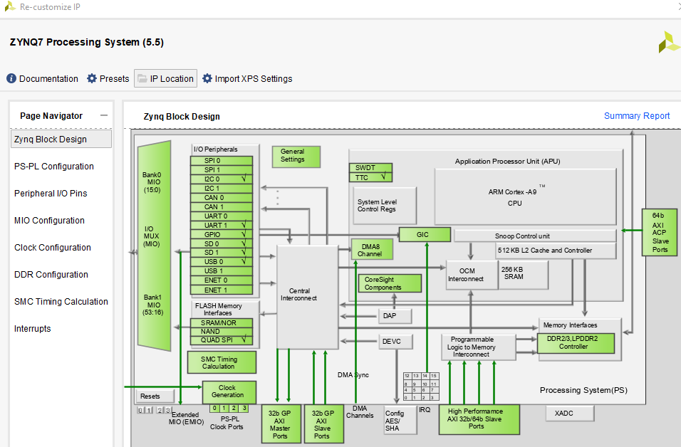
In my case, my idea is to add a PID controller to manage the speed of the motors of a mini drone by using the LIS2DS12 accelerometer of the MiniZed board. Here I have used the basic configuration shown in chapter 3 of the hardware training course, experience that I repeated here: MiniZed Board Peripheral Configuration. In summary we enable and Map all PS Peripherals as follows:
- The Quad SPI flash memory U46 provides 2 Gb of non-volatile storage that can be used for configuration and data storage. Check the box next to Quad SPI Flash:
- Also enable USB 0.
- Since for MiniZed, the USB 0 Peripheral requires a reset. Enable GPIO MIO by clicking the checkbox next to it.
- Also enable SD card.
- The UART1 was configured in Lesson 2 of hardware training course.

After copying the above project into a new folder called "motor-pwm-accel", I followed the instructions of Adam Taylor's tutorial: "Mini But Mighty, the MiniZed and Vitis for Motor Control":
- On the Peripheral IO Pins tab enable TTC0
- Under the MIO configuration, ensure the IO for timer 0 is set to EMIO.
- On the same tab I also enable a one bit GPIO and route this to the EMIO.
- Right click on the TTC0_WAVE0_OUT and select Make External.
- Do the same for the GPIO signal.
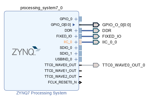
In addition, it´s necessary to select the II2C_0 port and make external. The Zynq block design looks like this:
The block looks as follows:
The next step is to create the HDL wrapper. Right click on the block diagram in the design sources window and select the Create HDL Wrapper.
Note: in case you need to make modifications to the hardware design, you must do "Reset output products" and then "Generate output products" in the HDL Wrapper.

Create and edit the Constraints file as follows:
io.xdc
set_property PACKAGE_PIN M15 [get_ports {TTC0_WAVE0_OUT_0 }];
set_property PACKAGE_PIN L15 [get_ports {GPIO_O_0 }];
set_property IOSTANDARD LVCMOS33 [get_ports TTC0_WAVE0_OUT_0]
set_property IOSTANDARD LVCMOS33 [get_ports GPIO_O_0]

# ----------------------------------------------------------------------------
# I2C bus -- ST Micro LIS2DS12TR Accelerometer and temperature
#            Dialog DA9062
# ----------------------------------------------------------------------------
# Bank 35
set_property PACKAGE_PIN G15 [get_ports {IIC_0_0_scl_io        }];  # "G15.I2C_SCL"
set_property PACKAGE_PIN F15 [get_ports {IIC_0_0_sda_io         }];  # "F15.I2C_SDA"
# Set the bank voltage for IO Bank 35 to 3.3V
set_property IOSTANDARD LVCMOS33 [get_ports -of_objects [get_iobanks 35]];
Select the Generate Bitstream Option and wait a few minutes while the design compiles.
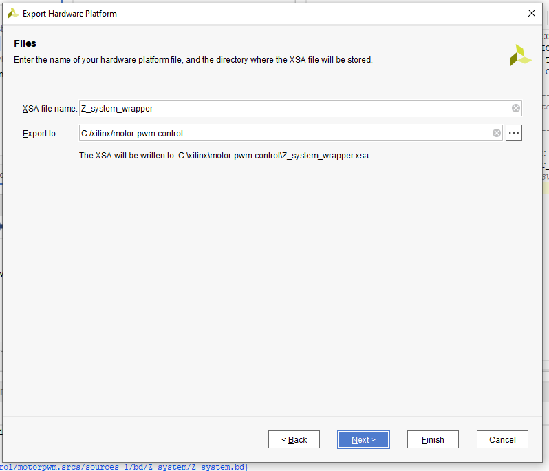
Export the XSA file as the tutorial indicates.
Software Build with Vitis IDE
Launch Vitis IDE and create a Workspace. In my case the workspace is C:\xilinx\motor-pwm-accel\Software.

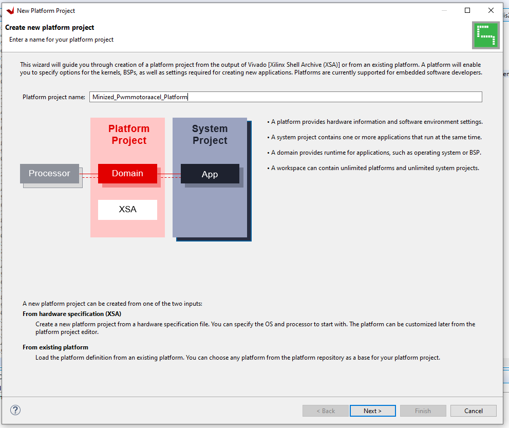
Create a new platform project and build it. In my case I name it as Minized_Pwmmotoraacel_Platform
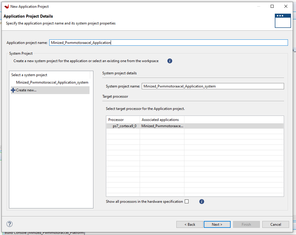
Also create the application project “Minized_Pwmmotoraacel_Application”. Here I selected the Hello World application.
Now insert the following code in the helloworld.c file
// AUTHOR: GUILLERMO PEREZ

#include <stdio.h>
#include <stdlib.h>
#include "platform.h"
#include "xil_printf.h"
#include "xgpiops.h"
#include "sleep.h"
#include "xil_exception.h"
#include "xttcps.h"
#include "xscugic.h"
#include "lis2ds12.h"
#include <math.h>

#define ACCEL_SCALE_VAL 100/2000
#define ACCEL_OFF_VAL  200

#define GPIO_DEVICE_ID XPAR_XGPIOPS_0_DEVICE_ID
#define INTC_DEVICE_ID XPAR_SCUGIC_0_DEVICE_ID
#define TICK_TIMER_FREQ_HZ 100
#define TTC_TICK_DEVICE_ID XPAR_XTTCPS_0_DEVICE_ID
#define TTC_TICK_INTR_ID XPAR_XTTCPS_0_INTR
static void TickHandler(void *CallBackRef);

int SetupTicker(XTtcPs *TtcPsInst, u16 DeviceID, u16 TtcTickIntrID, XScuGic *InterruptController);
static int SetupInterruptSystem(u16 IntcDeviceID, XScuGic *IntcInstancePtr);
int SetupTimer(u16 DeviceID, XTtcPs *TtcPsInst);
void set_pwm(u32 cycle);

typedef struct
{
    u32 OutputHz;       /* Output frequency */
    XInterval Interval; /* Interval value */
    u8 Prescaler;       /* Prescaler value */
    u16 Options;        /* Option settings */
} TmrCntrSetup;

XGpioPs Gpio;
XGpioPs_Config *ConfigPtr;
XTtcPs_Config *TtcConfig;
XTtcPs ttcTimer;
TmrCntrSetup *TimerSetup;
XScuGic InterruptController; /* Interrupt controller instance */
XTtcPs TtcPsInst;
u32 MatchValue;
static TmrCntrSetup SettingsTable = {TICK_TIMER_FREQ_HZ, 0, 0, 0};

int main()
{
    u8 DutyCycle;
    u8 DutyCycle2;
    char key_input;
    init_platform();
    sensor_init();

    // pid controller
    float setpoint_angle = 1.0; // reference angle is 0 degrees approx
    float integral = 0.0;
    float dt = 2.05; //  derivative constant
    float Kp = 3.55;  // proportional constant
    float Ki = 0.011;  // integral constant

    TmrCntrSetup SettingsTable = {TICK_TIMER_FREQ_HZ, 0, 0, 0};
    ConfigPtr = XGpioPs_LookupConfig(GPIO_DEVICE_ID);
    XGpioPs_CfgInitialize(&Gpio, ConfigPtr, ConfigPtr->BaseAddr);
    XGpioPs_SetDirectionPin(&Gpio, 54, 1);
    XGpioPs_SetOutputEnablePin(&Gpio, 54, 1);
    XGpioPs_WritePin(&Gpio, 54, 0x1);

    printf("Tunning drone motor\n\r");
    SetupInterruptSystem(INTC_DEVICE_ID, &InterruptController);
    SetupTicker(&ttcTimer, TTC_TICK_DEVICE_ID, TTC_TICK_INTR_ID, &InterruptController);

    int x_axis_current, z_axis_current;

    while (1)
    {
        if ( pollForAccel( &x_axis_current, &z_axis_current))
        {
        	x_axis_current = abs(x_axis_current);
            z_axis_current = abs(z_axis_current);
            float x_axis_current_1 = x_axis_current;
            float z_axis_current_1 = z_axis_current;
            float anglexz = (x_axis_current_1 / z_axis_current_1);
            float anglexz2 = atan(anglexz);
            float anglexz3 = anglexz2*(57.2958);

            float error_angle = abs (setpoint_angle -anglexz3);

        	if (error_angle < 6)
        	{
        		DutyCycle = 55.5; //48
        		DutyCycle2 = 100 - DutyCycle;
        	}

        	else
        	{
                integral =  (integral + (error_angle * dt));
                DutyCycle = ((Kp * error_angle) + (Ki * integral));
                DutyCycle2 = 100 - DutyCycle;
        		if (DutyCycle > 88)
        		{
        			DutyCycle = 88;
        			DutyCycle2 = 100 - DutyCycle;
        		}
        	}
        	set_pwm(DutyCycle);
        	printf("  AccelerationX :  %+5d, AccelerationZ :  %+5d, DutyCycle_M1 : %+5d, DutyCycle_M2 : %+5d, Angle : %+5f\r",x_axis_current, z_axis_current, DutyCycle, DutyCycle2, anglexz3);
        	//usleep(10000);
        }
    }
    cleanup_platform();
    return 0;
}

void set_pwm(u32 cycle)
{
    u32 MatchValue;
    MatchValue = (TimerSetup->Interval * cycle) / 100;
    XTtcPs_SetMatchValue(&ttcTimer, 0, MatchValue);
}

int SetupTicker(XTtcPs *TtcPsInst, u16 DeviceID, u16 TtcTickIntrID, XScuGic *InterruptController)
{
    int Status;
    TmrCntrSetup *TimerSetup;
    XTtcPs *TtcPsTick;
    TimerSetup = &SettingsTable;
    TimerSetup->Options |= (XTTCPS_OPTION_INTERVAL_MODE |
                            XTTCPS_OPTION_MATCH_MODE | XTTCPS_OPTION_WAVE_POLARITY);
    Status = SetupTimer(DeviceID, TtcPsInst);
    if (Status != XST_SUCCESS)
    {
        return Status;
    }
    TtcPsTick = TtcPsInst;
    Status = XScuGic_Connect(InterruptController, TtcTickIntrID,
                             (Xil_InterruptHandler)TickHandler, (void *)TtcPsTick);
    if (Status != XST_SUCCESS)
    {
        return XST_FAILURE;
    }
    XScuGic_Enable(InterruptController, TtcTickIntrID);
    XTtcPs_EnableInterrupts(TtcPsTick, XTTCPS_IXR_INTERVAL_MASK);
    XTtcPs_Start(TtcPsTick);
    return Status;
}

static int SetupInterruptSystem(u16 IntcDeviceID, XScuGic *IntcInstancePtr)
{
    int Status;
    XScuGic_Config *IntcConfig;
    IntcConfig = XScuGic_LookupConfig(IntcDeviceID);
    if (NULL == IntcConfig)
    {
        return XST_FAILURE;
    }
    Status = XScuGic_CfgInitialize(IntcInstancePtr, IntcConfig,
                                   IntcConfig->CpuBaseAddress);
    if (Status != XST_SUCCESS)
    {
        return XST_FAILURE;
    }
    Xil_ExceptionRegisterHandler(XIL_EXCEPTION_ID_IRQ_INT,
                                 (Xil_ExceptionHandler)XScuGic_InterruptHandler,
                                 IntcInstancePtr);
    Xil_ExceptionEnable();
    return XST_SUCCESS;
}

int SetupTimer(u16 DeviceID, XTtcPs *TtcPsInst)
{
    int Status;
    XTtcPs_Config *Config;
    XTtcPs *Timer;
    TmrCntrSetup *TimerSetup;
    TimerSetup = &SettingsTable;
    Timer = TtcPsInst;
    Config = XTtcPs_LookupConfig(DeviceID);
    if (NULL == Config)
    {
        return XST_FAILURE;
    }
    Status = XTtcPs_CfgInitialize(Timer, Config, Config->BaseAddress);
    if (Status != XST_SUCCESS)
    {
        return XST_FAILURE;
    }
    XTtcPs_SetOptions(Timer, TimerSetup->Options);
    XTtcPs_CalcIntervalFromFreq(Timer, TimerSetup->OutputHz,
                                &(TimerSetup->Interval), &(TimerSetup->Prescaler));
    XTtcPs_SetInterval(Timer, TimerSetup->Interval);
    XTtcPs_SetPrescaler(Timer, TimerSetup->Prescaler);
    return XST_SUCCESS;
}

void TickHandler(void *CallBackRef)
{
    u32 StatusEvent;
    /*
* Read the interrupt status, then write it back to clear the interrupt.
*/
    StatusEvent = XTtcPs_GetInterruptStatus((XTtcPs *)CallBackRef);
    XTtcPs_ClearInterruptStatus((XTtcPs *)CallBackRef, StatusEvent);
    //printf("timer\n\r");
    /*update the flag if interrupt has been occurred*/
    //UpdateFlag = TRUE;
}
Copy the next two files of the library accelerometer into the src project.
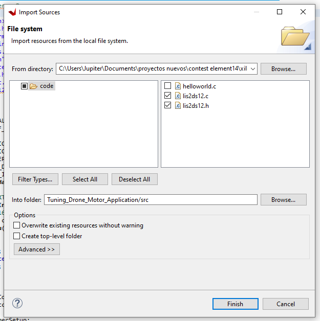
lis2ds12.c
#include <stdbool.h>
#include <stdio.h>
#include <unistd.h>
#include "platform.h"
#include "xil_printf.h"

#include "xparameters.h"
#include "xiicps.h"
#include "xil_printf.h"

#include "lis2ds12.h"

/* The original code was
 * https://www.element14.com/community/thread/66802/l/i2csensor-app-source-code
 *
 */

/************************** Constant Definitions ******************************/

/*
 * The following constants map to the XPAR parameters created in the
 * xparameters.h file. They are defined here such that a user can easily
 * change all the needed parameters in one place.
 */


#define IIC_DEVICE_ID		XPAR_XIICPS_0_DEVICE_ID

/*
 * The slave address to send to and receive from.
 */
#define IIC_SLAVE_ADDR		0x55
#define IIC_SCLK_RATE		100000

XIicPs Iic;		/**< Instance of the IIC Device */

#define MINIZED_MOTION_SENSOR_ADDRESS_SA0_HI  0x1D /* 0011101b for LIS2DS12 on MiniZed when SA0 is pulled high*/

#define TEST_BUFFER_SIZE 32
/*
 * The following buffers are used in this example to send and receive data
 * with the IIC.
 */
u8 SendBuffer[TEST_BUFFER_SIZE];    /**< Buffer for Transmitting Data */
u8 RecvBuffer[TEST_BUFFER_SIZE];    /**< Buffer for Receiving Data */


int IicPsMasterPolledExample()
{
	int Status;
	XIicPs_Config *Config;
	int Index;

	/*
	 * Initialize the IIC driver so that it's ready to use
	 * Look up the configuration in the config table,
	 * then initialize it.
	 */
	Config = XIicPs_LookupConfig(IIC_DEVICE_ID);
	if (NULL == Config) {
		return XST_FAILURE;
	}

	Status = XIicPs_CfgInitialize(&Iic, Config, Config->BaseAddress);
	if (Status != XST_SUCCESS) {
		return XST_FAILURE;
	}

	/*
	 * Perform a self-test to ensure that the hardware was built correctly.
	 */
	Status = XIicPs_SelfTest(&Iic);
	if (Status != XST_SUCCESS) {
		return XST_FAILURE;
	}

	/*
	 * Set the IIC serial clock rate.
	 */
	XIicPs_SetSClk(&Iic, IIC_SCLK_RATE);

	return XST_SUCCESS;

}


u8 LIS2DS12_WriteReg(u8 Reg, u8 *Bufp, u16 len)
{
	SendBuffer[0] = Reg;
	int Status;
	for (int ByteCount = 1;ByteCount <= len; ByteCount++)
	{
		SendBuffer[ByteCount] = Bufp[ByteCount-1];
	}

	/*
	 * Send the buffer using the IIC and ignore the number of bytes sent
	 * as the return value since we are using it in interrupt mode.
	 */
	Status = XIicPs_MasterSendPolled(&Iic, SendBuffer,	 (len+1), MINIZED_MOTION_SENSOR_ADDRESS_SA0_HI);
	if (Status != XST_SUCCESS) {
		return XST_FAILURE;
	}

	/*
	 * Wait until bus is idle to start another transfer.
	 */
	while (XIicPs_BusIsBusy(&Iic)) {
		/* NOP */
	}

	return XST_SUCCESS;
}

u8 LIS2DS12_ReadReg(uint8_t Reg, uint8_t *Bufp, uint16_t len)
{
	int Status;
	SendBuffer[0] = Reg;

	/*
	 * Send the buffer using the IIC and ignore the number of bytes sent
	 * as the return value since we are using it in interrupt mode.
	 */
	Status = XIicPs_MasterSendPolled(&Iic, SendBuffer,1, MINIZED_MOTION_SENSOR_ADDRESS_SA0_HI);
	if (Status != XST_SUCCESS) {
		return XST_FAILURE;
	}

	/*
	 * Wait until bus is idle to start another transfer.
	 */
	while (XIicPs_BusIsBusy(&Iic)) {
		/* NOP */
	}

	Status = XIicPs_MasterRecvPolled(&Iic, Bufp, len, MINIZED_MOTION_SENSOR_ADDRESS_SA0_HI);
	if (Status != XST_SUCCESS) {
		return XST_FAILURE;
	}

	while (XIicPs_BusIsBusy(&Iic)) {
		/* NOP */
	}

	return XST_SUCCESS;
}


bool isSensorConnected()
{
	uint8_t who_am_i = 0;
	uint8_t send_byte;

	LIS2DS12_ReadReg(LIS2DS12_ACC_WHO_AM_I_REG, &who_am_i, 1);
	printf("With I2C device address 0x%02x received WhoAmI = 0x%02x\r\n", MINIZED_MOTION_SENSOR_ADDRESS_SA0_HI, who_am_i);
	if (who_am_i != LIS2DS12_ACC_WHO_AM_I)
	{
		//maybe the address bit was changed, try the other one:
		LIS2DS12_ReadReg(LIS2DS12_ACC_WHO_AM_I_REG, &who_am_i, 1);
		printf("With I2C device address 0x%02x received WhoAmI = 0x%02x\r\n", MINIZED_MOTION_SENSOR_ADDRESS_SA0_HI, who_am_i);
	}
	send_byte = 0x00; //No auto increment
	LIS2DS12_WriteReg(LIS2DS12_ACC_CTRL2, &send_byte, 1);

	//Write 60h in CTRL1	// Turn on the accelerometer.  14-bit mode, ODR = 400 Hz, FS = 2g
	send_byte = 0x60;
	LIS2DS12_WriteReg(LIS2DS12_ACC_CTRL1, &send_byte, 1);
	printf("CTL1 = 0x60 written\r\n");

	//Enable interrupt
	send_byte = 0x01; //Acc data-ready interrupt on INT1
	LIS2DS12_WriteReg(LIS2DS12_ACC_CTRL4, &send_byte, 1);
	printf("CTL4 = 0x01 written\r\n");
	return true;

}
bool sensor_init()
{
	if (XST_SUCCESS != IicPsMasterPolledExample())
	{
		return false;
	}
	isSensorConnected();

	return true;
}


int u16_2s_complement_to_int(u16 word_to_convert)
{
	u16 result_16bit;
	int result_14bit;
	int sign;

	if (word_to_convert & 0x8000)
	{ //MSB is set, negative number
		//Invert and add 1
		sign = -1;
		result_16bit = (~word_to_convert) + 1;
	}
	else
	{ //Positive number
		//No change
		sign = 1;
		result_16bit = word_to_convert;
	}
	//We are using it in 14-bit mode
	//All data is left-aligned.  So convert 16-bit value to 14-but value
	result_14bit = sign * (int)(result_16bit >> 2);
	return(result_14bit);
} //u16_2s_complement_to_int()


bool pollForAccel(int *x, int *z)
{
		int iacceleration_X;
		int iacceleration_Y;
		int iacceleration_Z;
		u8 read_value_LSB;
		u8 read_value_MSB;
		u16 accel_X;
		u16 accel_Y;
		u16 accel_Z;
		u8 accel_status;
		u8 data_ready;

		data_ready = 0;

		 //wait for DRDY
		LIS2DS12_ReadReg(LIS2DS12_ACC_STATUS, &accel_status, 1);
		data_ready = accel_status & 0x01; //bit 0 = DRDY
		if (!data_ready)
			return false;

		//wait for DRDY


		//Read X:
		LIS2DS12_ReadReg(LIS2DS12_ACC_OUT_X_L, &read_value_LSB, 1);
		LIS2DS12_ReadReg(LIS2DS12_ACC_OUT_X_H, &read_value_MSB, 1);
		accel_X = (read_value_MSB << 8) + read_value_LSB;
		iacceleration_X = u16_2s_complement_to_int(accel_X);
		//Read Y:
		LIS2DS12_ReadReg(LIS2DS12_ACC_OUT_Y_L, &read_value_LSB, 1);
		LIS2DS12_ReadReg(LIS2DS12_ACC_OUT_Y_H, &read_value_MSB, 1);
		accel_Y = (read_value_MSB << 8) + read_value_LSB;
		iacceleration_Y = u16_2s_complement_to_int(accel_Y);
		//Read Z:
		LIS2DS12_ReadReg(LIS2DS12_ACC_OUT_Z_L, &read_value_LSB, 1);
		LIS2DS12_ReadReg(LIS2DS12_ACC_OUT_Z_H, &read_value_MSB, 1);
		accel_Z = (read_value_MSB << 8) + read_value_LSB;
		iacceleration_Z = u16_2s_complement_to_int(accel_Z);

		if (x)
		{
			*x = iacceleration_X;
		}

//		if (y)
//		{
//			*y = iacceleration_Y;
//		}

		if (z)
		{
			*z = iacceleration_Z;
		}

	//	printf("  Acceleration = X: %+5d, Y: %+5d, Z: %+5d\r\n",iacceleration_X, iacceleration_Y, iacceleration_Z);
//		printf("  Acceleration = X: %+5d, Y: %+5d, Z: %+5d\r",iacceleration_X, iacceleration_Y, iacceleration_Z);

		return true;
}
lis2ds12.h
#include <stdbool.h>
extern bool sensor_init(void);
extern bool pollForAccel(int *x, int *y );


/*
 * The following constant defines the address of the IIC device on the IIC bus.  Note that since
 * the address is only 7 bits, this  constant is the address divided by 2.
 */
#define MAGNETOMETER_ADDRESS  0x1E /* LIS3MDL on Arduino shield */
#define MINIZED_MOTION_SENSOR_ADDRESS_SA0_LO  0x1E /* 0011110b for LIS2DS12 on MiniZed when SA0 is pulled low*/
#define MINIZED_MOTION_SENSOR_ADDRESS_SA0_HI  0x1D /* 0011101b for LIS2DS12 on MiniZed when SA0 is pulled high*/

#define LIS2DS12_ACC_WHO_AM_I         0x43
/************** Device Register  *******************/
#define LIS2DS12_ACC_SENSORHUB_OUT1  	0X06
#define LIS2DS12_ACC_SENSORHUB_OUT2  	0X07
#define LIS2DS12_ACC_SENSORHUB_OUT3  	0X08
#define LIS2DS12_ACC_SENSORHUB_OUT4  	0X09
#define LIS2DS12_ACC_SENSORHUB_OUT5  	0X0A
#define LIS2DS12_ACC_SENSORHUB_OUT6  	0X0B
#define LIS2DS12_ACC_MODULE_8BIT  	0X0C
#define LIS2DS12_ACC_WHO_AM_I_REG  	0X0F
#define LIS2DS12_ACC_CTRL1  	0X20
#define LIS2DS12_ACC_CTRL2  	0X21
#define LIS2DS12_ACC_CTRL3  	0X22
#define LIS2DS12_ACC_CTRL4  	0X23
#define LIS2DS12_ACC_CTRL5  	0X24
#define LIS2DS12_ACC_FIFO_CTRL  	0X25
#define LIS2DS12_ACC_OUT_T  	0X26
#define LIS2DS12_ACC_STATUS  	0X27
#define LIS2DS12_ACC_OUT_X_L  	0X28
#define LIS2DS12_ACC_OUT_X_H  	0X29
#define LIS2DS12_ACC_OUT_Y_L  	0X2A
#define LIS2DS12_ACC_OUT_Y_H  	0X2B
#define LIS2DS12_ACC_OUT_Z_L  	0X2C
#define LIS2DS12_ACC_OUT_Z_H  	0X2D
#define LIS2DS12_ACC_FIFO_THS  	0X2E
#define LIS2DS12_ACC_FIFO_SRC  	0X2F
#define LIS2DS12_ACC_FIFO_SAMPLES  	0X30
#define LIS2DS12_ACC_TAP_6D_THS  	0X31
#define LIS2DS12_ACC_INT_DUR  	0X32
#define LIS2DS12_ACC_WAKE_UP_THS  	0X33
#define LIS2DS12_ACC_WAKE_UP_DUR  	0X34
#define LIS2DS12_ACC_FREE_FALL  	0X35
#define LIS2DS12_ACC_STATUS_DUP  	0X36
#define LIS2DS12_ACC_WAKE_UP_SRC  	0X37
#define LIS2DS12_ACC_TAP_SRC  	0X38
#define LIS2DS12_ACC_6D_SRC  	0X39
#define LIS2DS12_ACC_STEP_C_MINTHS  	0X3A
#define LIS2DS12_ACC_STEP_C_L  	0X3B
#define LIS2DS12_ACC_STEP_C_H  	0X3C
#define LIS2DS12_ACC_FUNC_CK_GATE  	0X3D
#define LIS2DS12_ACC_FUNC_SRC  	0X3E
#define LIS2DS12_ACC_FUNC_CTRL  	0X3F
If you build the project you may get errors because you haven't added the math.h library properly. Then, with right click open properties of application project, and insert the letter m in the libraries tab as shown below:

This code helps us to calculate the inclination angle indirectly with the accelerometer of the MiniZed board. If the angle is greater than 5 degrees then the PID control corrects the error so that the motors keep the drone within this threshold. Next I give you more details on how to calculate the angle of inclination with the accelerometer, and how to adjust the PID controller.
Finding Angle Of Inclination with the LIS2DS12 accelerometer
An inclinometer is a device that allows us to measure the inclination in degrees of a surface. Through the accelerometer of the LIS2DS12 we can measure the acceleration of a moving system or device. The LIS2DS12 is an ultra-low-power, high-performance three-axis linear accelerometer belonging to the “pico” family which leverages on the robust and mature manufacturing processes already used for the production of micromachined accelerometers. The LIS2DS12 has user-selectable full scales of ±2g/±4g/±8g/±16g and is capable of measuring accelerations with output data rates from 1 Hz to 6400 Hz.

By geometry, the angle drawn (Θ) by the weight vector W with the Wz axis is equal to the angle (Θ) of the inclined plane of the diagram. So the angle theta (Θ) is equal to the arc tangent of (Wx/Wz).
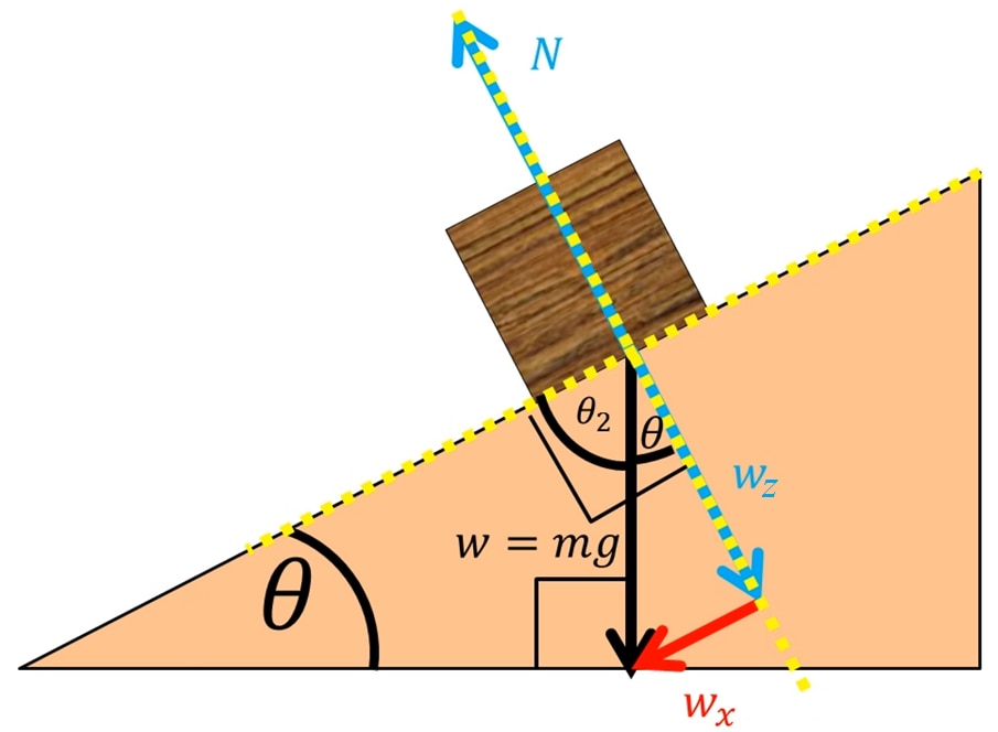
The idea is quite simple, we are all under the influence of gravity, the accelerometer will allow us to know the direction of this force and we will only apply some simple trigonometric formulas to calculate the inclination of the sensor.
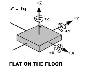
The accelerometer as such never knows its position. However he knows the components of the force of gravity. We can use the values of the force that is applied to the components to know the angle, using a simple inverse trigonometric function:
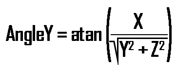
In my case, I will use the X axis of the accelerometer, so the Y axis accelerometer is zero, and the formula reduces to:

The part of the code that calculates the tilt angle is:
    while (1)
    {
        if ( pollForAccel( &x_axis_current, &z_axis_current))
        {
        	x_axis_current = abs(x_axis_current);
            z_axis_current = abs(z_axis_current);
            float x_axis_current_1 = x_axis_current;
            float z_axis_current_1 = z_axis_current;
            float anglexz = (x_axis_current_1 / z_axis_current_1);
            float anglexz2 = atan(anglexz);
            float anglexz3 = anglexz2*(57.2958);
PID Controller
A proportional–integral–derivative controller (PID controller) is a control loop mechanism employing feedback that is widely used in industrial control systems and a variety of other applications requiring continuously modulated control. A PID controller continuously calculates an error value e(t) as the difference between a desired set point (SP) and a measured process variable (PV) and applies a correction based on proportional, integral, and derivative terms (denoted P, I, and D respectively). https://en.wikipedia.org/wiki/PID_controller. You can find many references of PID controller applications, here I show you some personal ones and others:
- https://www.hackster.io/guillengap/pid-light-meter-controller-724672;
- https://hackaday.io/project/181361-uv-sanitizing-autonomous-robot/log/197114-step-7-pid-controller;
- http://electronoobs.com/eng_robotica_tut6.php
For the balance we will use just one axis. So, I've choose the x angle to implement the PID controller. That means that the x axis of the accelerometer has to be parallel to the balance. In my case, MiniZed board generates a PWM signal of 100 Hz, and the control data are:
    // pid controller
    float setpoint_angle = 1.0; // reference angle
    float integral = 0.0;
    float dt = 2.05;
    float Kp = 3.55;
    float Ki = 0.011;
The simulation of this PID system would be the following:

When the system is balanced, the duty cycle of both motors is 50% approx (left and right).
First, we calculate the error between the desired angle and the real measured angle.
float error_angle = abs (setpoint_angle -anglexz3);
The MiniZed board uses PID controller to maintain on the desire angle the balance. If the left side increase the desire angle, then it can decrease the speed of the right motor and increase the speed of the left motor, to make the balance move to the right side.
                integral =  (integral + (error_angle * dt));
                DutyCycle = ((Kp * error_angle) + (Ki * integral));
                DutyCycle2 = 100 - DutyCycle;
If the right side increases the desire angle, then it can decrease the speed of the left motor and increase the speed of the right motor, to make the balance move to the left side.
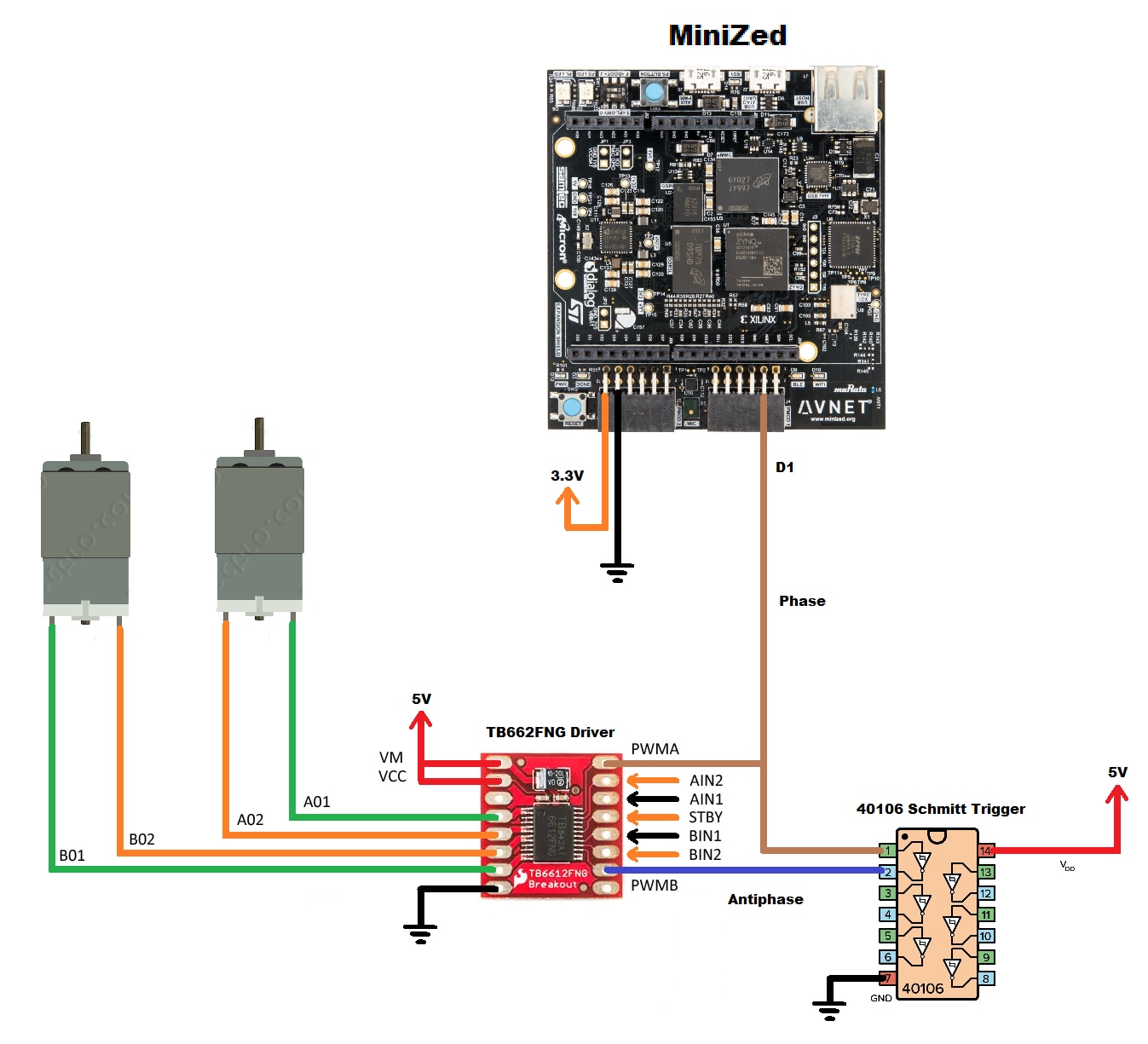
In other words, on the left side motor I generate a PWM signal called phase, and on the right side motor I generate an antiphase PWM signal.
In my solution in the motor on the left side I have generated a phase PWM signal by software, and in the motor on the right side I have generated an antiphase PWM signal by hardware as you will see in the schematic diagram in the next section.
Hardware Assembly
Below I show you the schematic diagram of my project:
The docs for most PMOD look like this, with pin 1 on the right side:
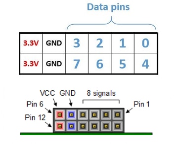
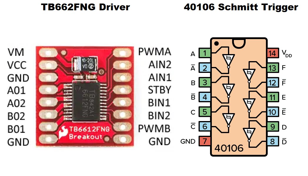
I also attach the pinout diagram of the TB662FNG Driver and 40106 Schmitt Trigger.
First we are going to build the structure of the balance. In my case I used an aluminum alloy due to its low weight, just like real airplanes. Below I show you the pieces used with their dimensions.
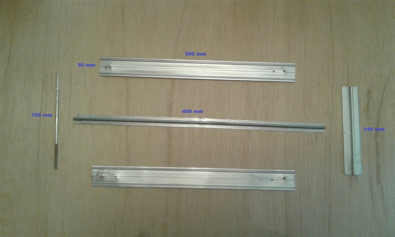
Assembling the scale is very easy; you only need a drill and several screws. You also have to add a piece of wood as a support with dimensions 140(L) x 70(W) x 15(H) mm.

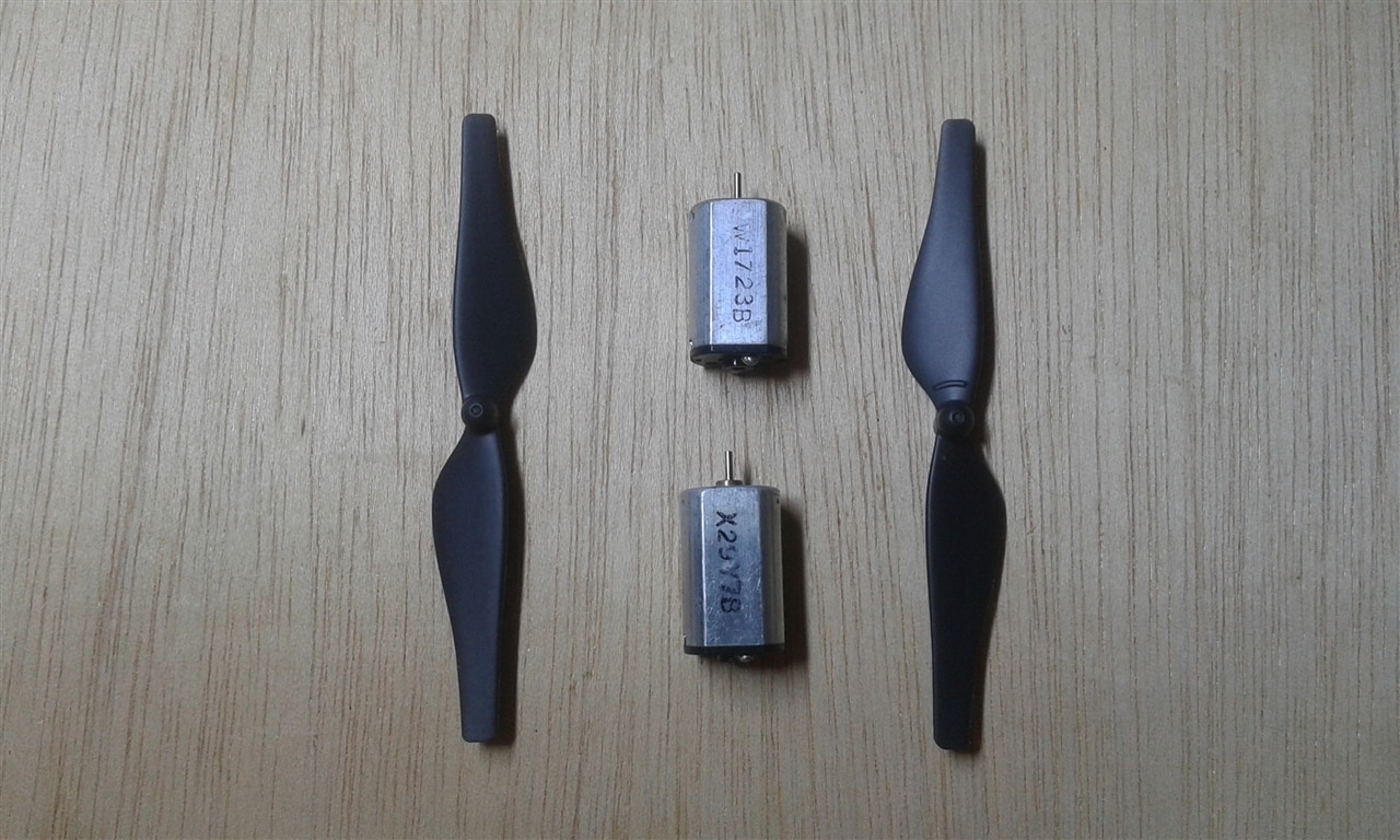
The next step is to assemble the DC motors with the propellers. These motors are generic 3V. In the tests and conclusions I will comment my experience with this type of engine.
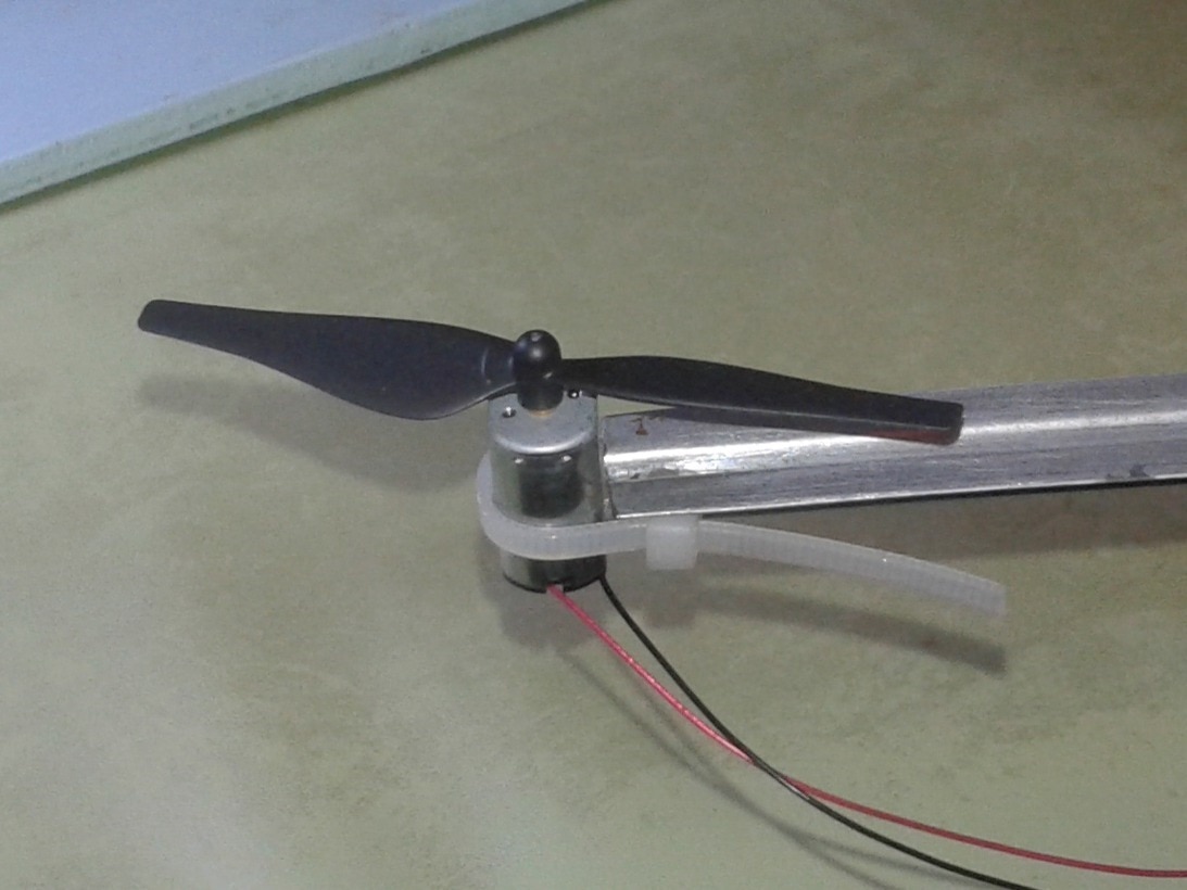
I have attached the motors and propellers using pliers and drilling the ends of the aluminum shaft.
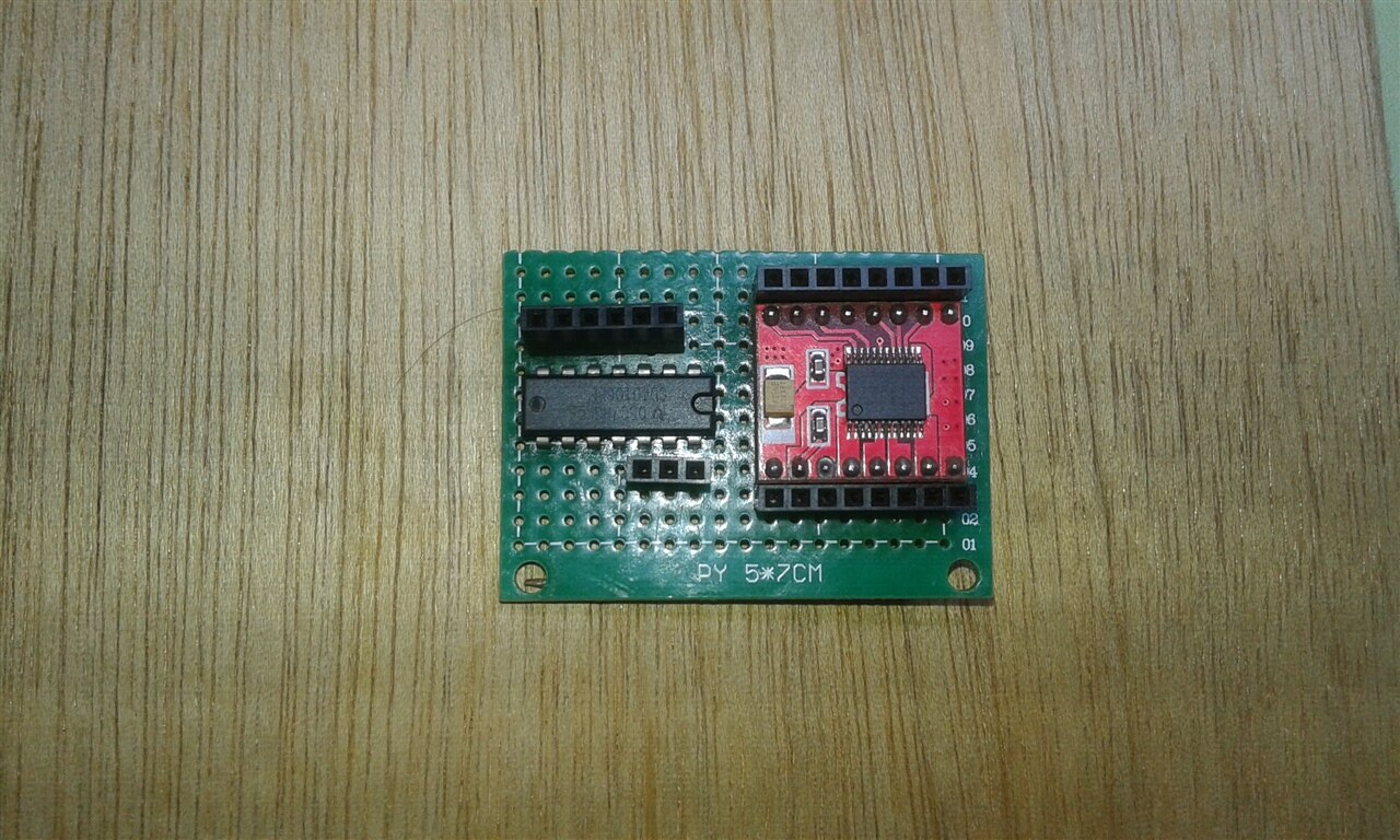
According to the schematic diagram we should solder the TB662FNG driver and the 40106 Schmitt Trigger as shown below.
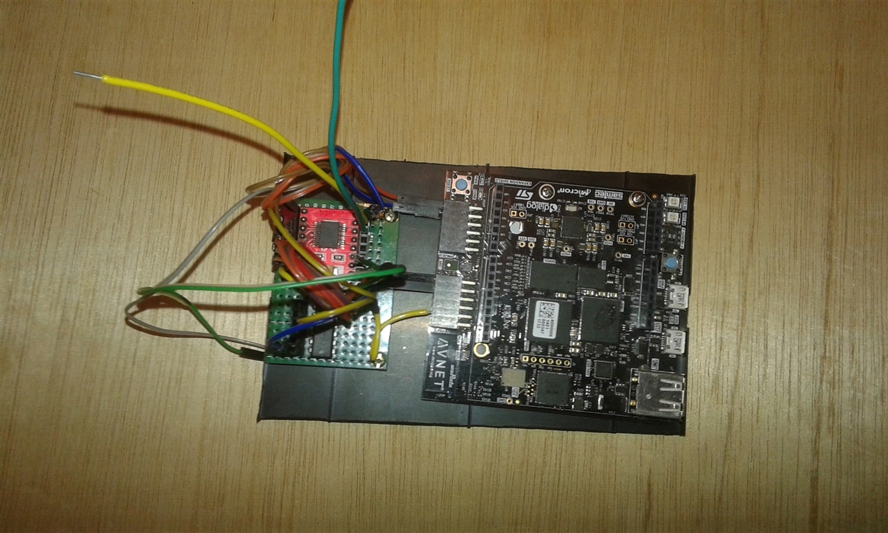
In the same way, I have assembled the Minized board and the hardware devices on a plastic base of 180(L) x 80(W) mm.
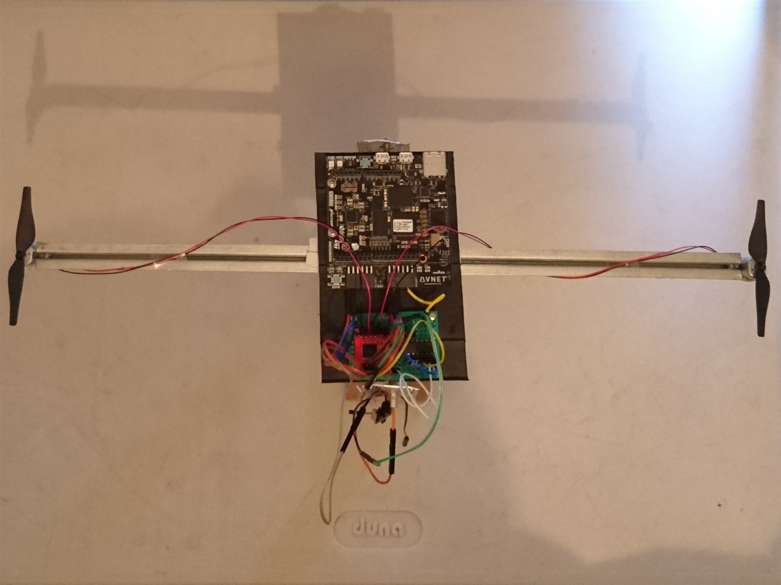
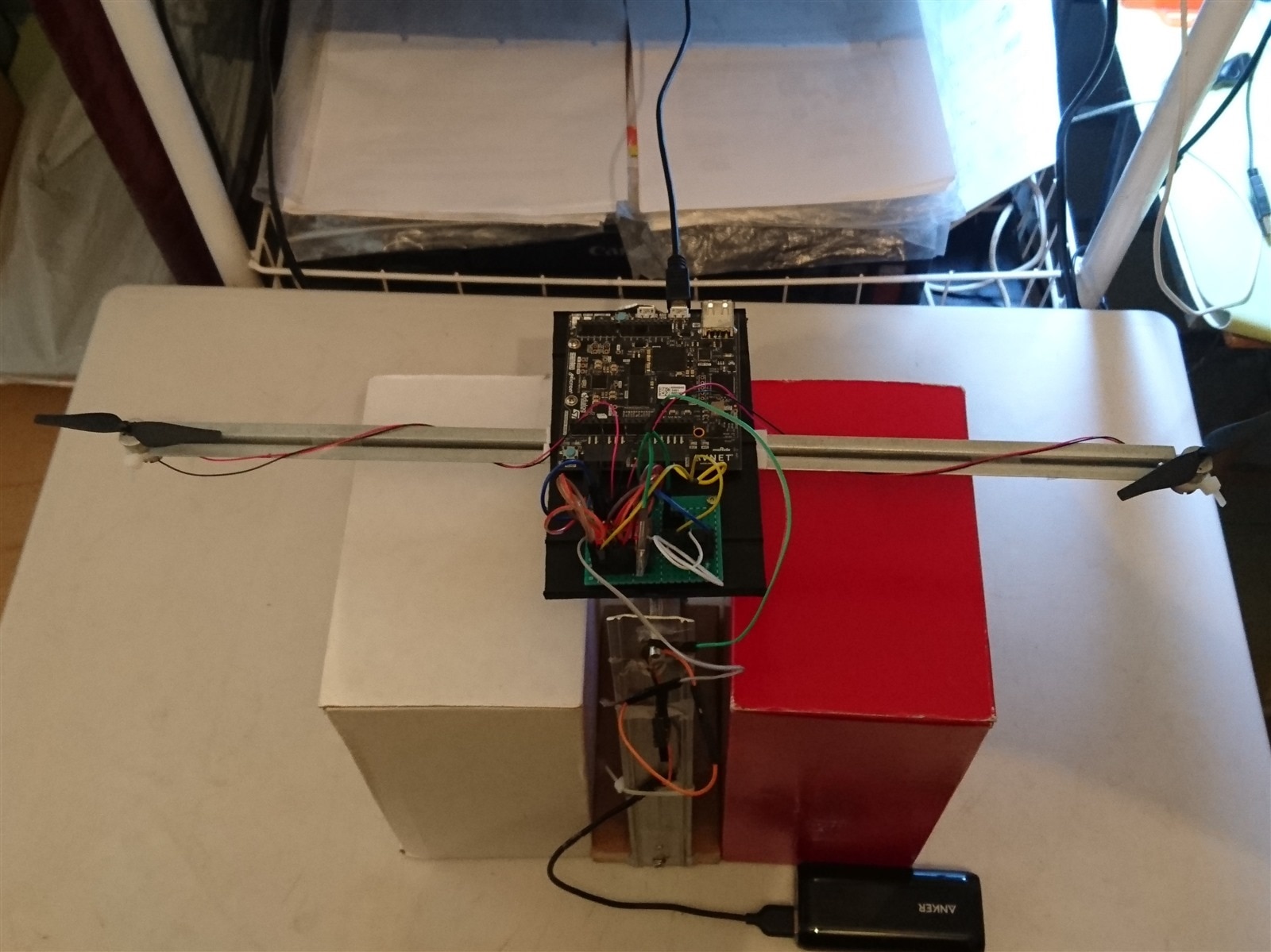
The device mounted on the scale is shown below; I have put two boxes on the sides to support the motor shaft when they are turned off.
Test
In the video below I show you a test carried out to trace the PWM signals generated from the prototype before mounting it on the scale.
Finally, we start the debugger and run the code. Below you can see the final test video.
Conclusion
This project is didactic to learn how to calibrate the drone motors, below I show you some tips that can be useful to repeat the experience:
- In my case I have used a PWM signal to generate the PWM signals of the two motors since the PWM signal of the second motor is the antiphase of the first motor.
- When the axis of the two motors is in balance, the PWM signals of both motors are 50% (X-accelerometer of the LIS2DS12).
- When the system is unbalanced, the PID controller calculates the angle error and increases the duty cycle on the lower motor and decreases the duty cycle on the upper motor until the angle is approximately 1 degree.
- You can experiment with more PWM signals, but keep in mind that the PID controller calculates the angle error, which will add on one PWM signal, and subtract on the other PWM signal.
- In my case the PID control constants were the following: dt = 2.05 (derivative), Kp = 3.55 (proportional), and Ki = 0.011(integral). However you can use other values according to your design.
Github repository
References
- https://www.st.com/en/mems-and-sensors/lis2ds12.html
- https://www.hackster.io/adam-taylor/mini-but-mighty-the-minized-and-vitis-for-motor-control-9c376b#toc-wrap-up-4
- https://www.hackster.io/MichalsTC/mini-but-mighty-motor-control-via-builtin-accelerometer-221619
- http://electronoobs.com/eng_robotica_tut6.php


