Blog # 1 - Project Description And Upgrade Installation
Blog # 2 - MiniZed Board Peripheral Configuration and Creating a Boot Image
Blog # 3 - Executing Vivado Design Suite TCL Commands
Blog # 4 - Move Data Between BRAM and DDR3 Memories
Blog # 5 - How to Enable Interrupts With MiniZed
**********************************************************************************************************************
Hi everyone! In this tutorial I am going to do a review and summary of Lesson 3 of the MiniZed training course. These steps are important since a good configuration decreases the probability of errors in the operation of a final project. I also add an experiment with the creation of Boot Image since from this configuration it is possible to do it to Flash the board.
Enable and Map all PS Peripherals
According to lesson 3 of the MiniZed board training course posted at the link: MiniZed Hardware Technical Training 2021.1: Lesson 3
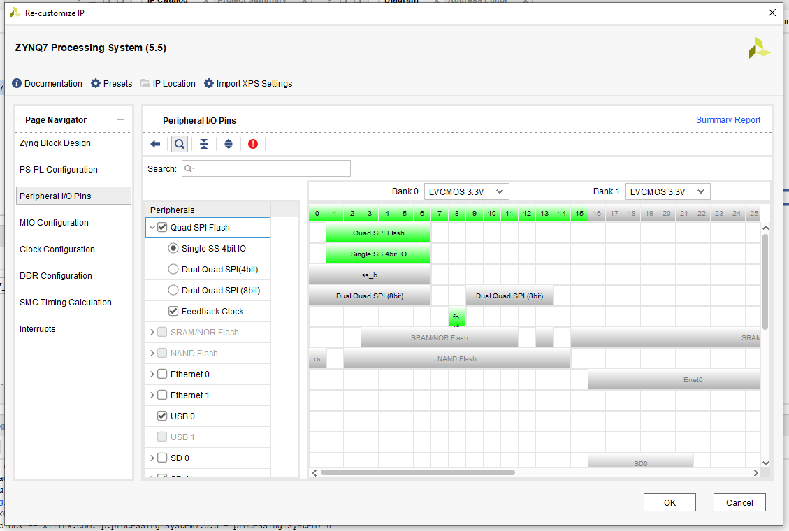
- The Quad SPI flash memory U46 provides 2 Gb of non-volatile storage that can be used for configuration and data storage. So, check the box next to Quad SPI Flash:
- Also enable USB 0, and look at the pull-down menu.
The MIO interface allows the ARM to access external pins without routing signals through the FPGA. So, in MIO Configuration:
- Since for MiniZed, the USB 0 Peripheral requires a reset. Enable GPIO MIO by clicking the checkbox next to it. Then click the checkbox next to USB Reset.
- Also enable SD card or eMMC
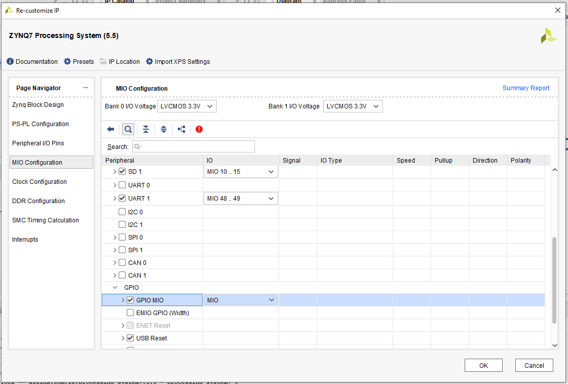
Final I/O Peripheral Connections are shown below. Remember that UART1 was configured in Lesson 2.
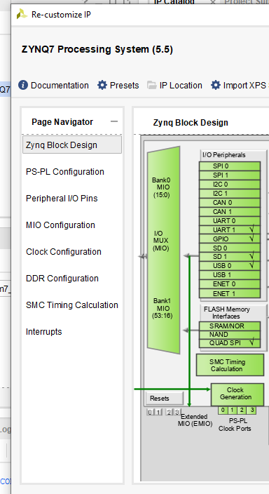
Set the PS PLL Clocks
A phase-locked loop (PLL) is a feedback circuit designed to allow one circuit board to synchronize the phase of its on board clock with an external timing signal. PLL circuits operate by comparing the phase of an external signal to the phase of a clock signal produced by a voltage controlled crystal oscillator (VCXO). This lesson only shows how to do the PLL configuration, and for the moment they will not be used in this lesson.
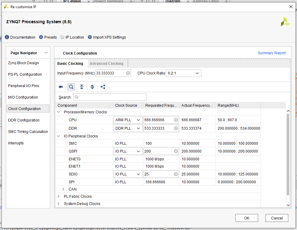
In Clock Configuration
- Review the settings previously entered/verified for PS clocks.
- Set the SDIO to 25MHz on MiniZed boards.
- Close the Zynq Block Design by clicking OK.
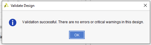
- Validate (F6) the Block Design.
- Save the Block Design.
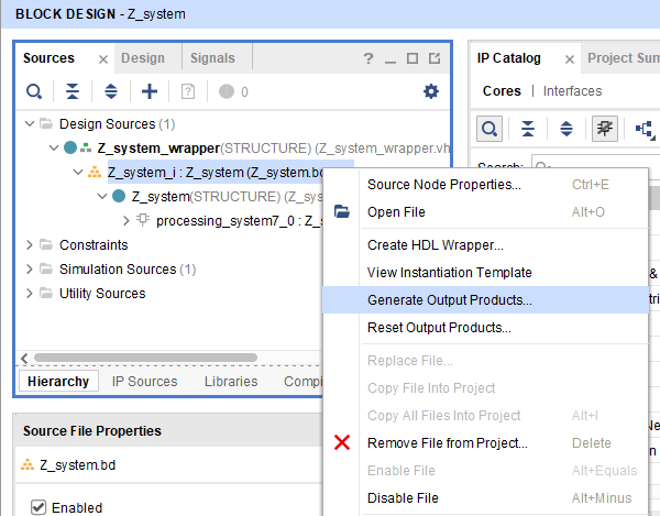
Every time we change the hardware configuration in Vivado, it will be necessary to repeat the following steps. Select the Design Sources. Right-click on the Z_system_i item and select Reset Output Products
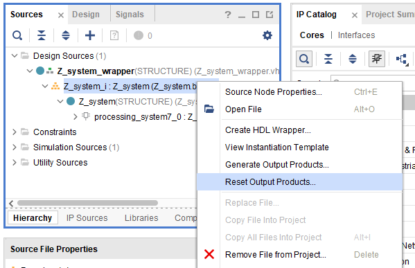
- Now right-click on Z_system_i again, but this time select Generate Output Products,
- Select Generate Bitstream,
Create and Run Test Applications
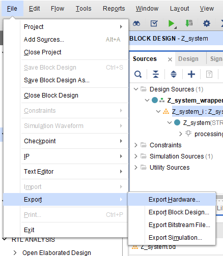
We export to Vitis as we did in Lab 2: Select File - Export - Export Hardware
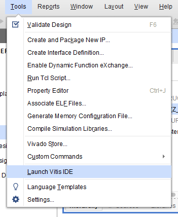
From the pull-down menus at the top of Vivado, select Tools - Launch Vitis IDE
- As we saw in Lesson 2, we change the Workspace to ZynqDesign_lab3
- Then we create a "MiniZed_Perpherial_Test_Platform" platform project: New - Platform Project
- Then we select a new Application file project: Hello_World_MiniZed_Perpherial_App
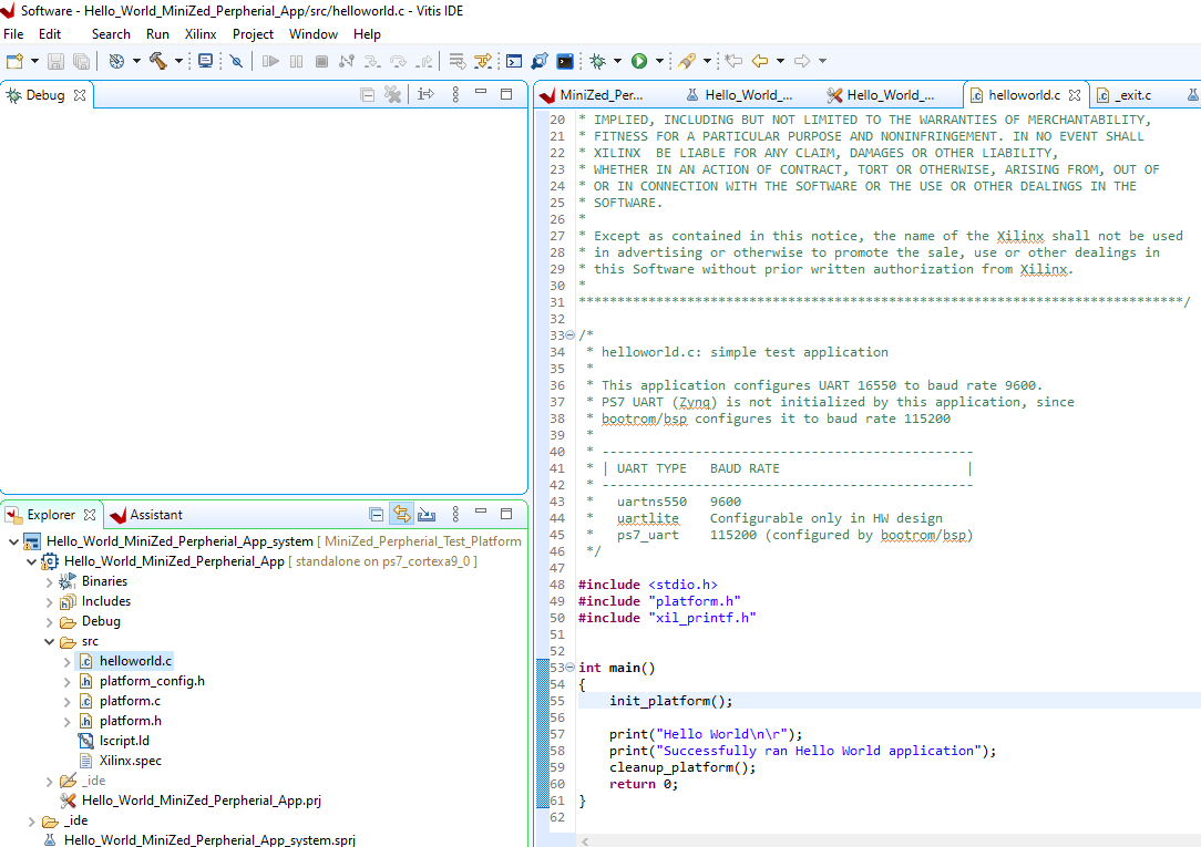
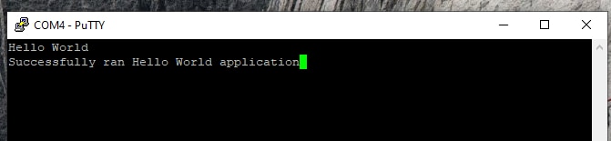
Now we build and debug the project. Below we can see the output in the serial port.
We repeat the previous steps, but this time, we generate the Memory Test application.
- File - New - Application Project
- Select the Platform again
- We create a new application and name it MiniZed_Memory_Test
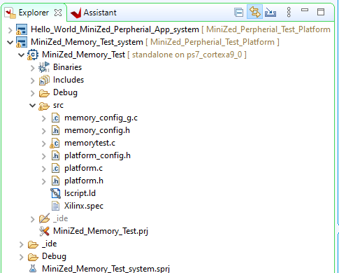
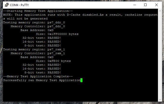
Below we see the output through the serial port.
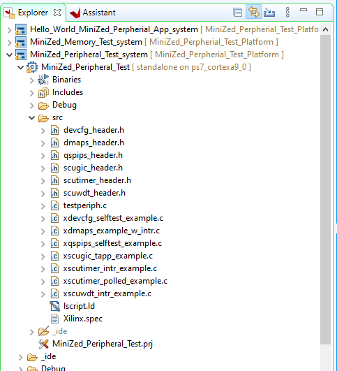
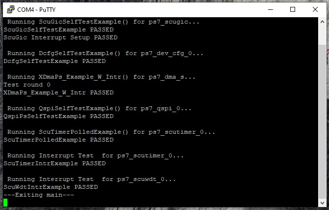
Finally, we generate the Peripheral Test application.
- File - New - Application Project
- Select the Platform again
- We create a new application and name it MiniZed_Periphral_Test
The output serial port will be as follow:
BOOT.BIN contains the FPGA configuration and PMU firmware. All the official information can be found here: https://www.xilinx.com/htmldocs/xilinx2019_1/SDK_Doc/SDK_tasks/task_creatingabootimage.html
This time we are going to not only boot the processor but also program the Flash NVRAM. Once the application is pasted into the software application and the project up to date. Select the Application project, right click on it and select "Create Boot Image"

The boot image creation dialog will show the order of the files to be included in the configuration process. This includes the FSBL, BIT and Application.

Once the boot image is available, we can use Vitis to write the flash into the memory.

To program the memory we have a very simple option of selecting program flash: Select the Application project, right click on it and select "Program Flash"

The flash download configuration is something like this:

This will take a few minutes to get download the flash.

When it completes you will see a image like the one below.

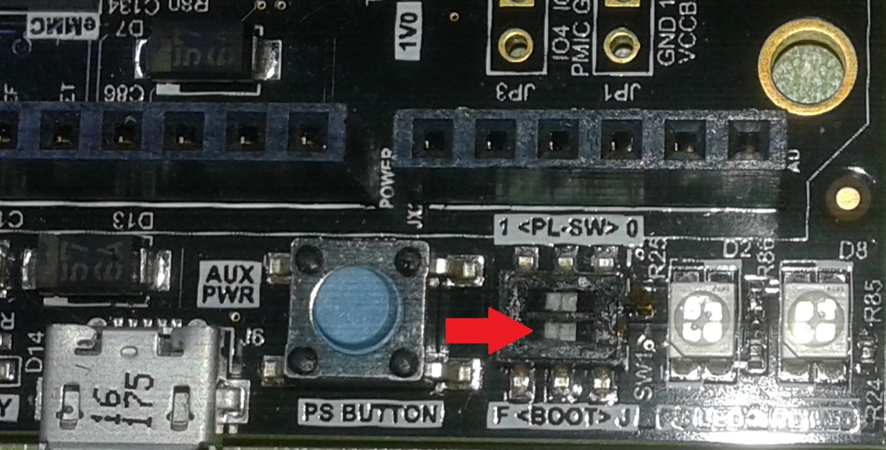
After previous steps, set the MiniZed boot mode switch SW1 to QSPI mode (‘F’ for Flash) as shown below, and you are ready to see your board running.