After a series of timeline delays due a lot of (several) personal troubles I can restart the publication of the project blog posts with some smart updates. The project is near to be finished and in few days also the presentation location and dates will be official.
Full 3D printed
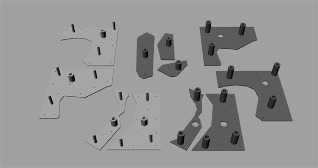
The Art-a-tronic opera is totally 3D printed and the final assembly has been finished. To make the final moving object (35x35x20 cm size) it was necessary to design 28 different mechanical parts resulting in 41 different printed pieces:
- 13 White parts: the image background
- 7 Blue parts: the moving shapes of the image
- 11 Black parts: elements and supports to make the blue parts moving
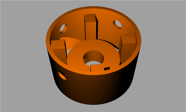
- 7 Orange parts: to lock the special nut moved by the vertical axis
- 4 Red parts: to create the support base and the stepper motors support to the bottom of the moving elements.
| {gallery} Components design |
|---|
The white parts composing the background exposed surface (35x35 cm) |
The four blue parts composing the main shape. These parts moves toward the viewer laying on the white background |
The three blue parts composing the image details (eyes, nose and lips). These parts moves inside the background holes from the bottom of the base |
The eleven black parts supporting the blue parts movements |
The four red parts. When assembled these are the main base of the entire structure. |
The special nut motion screw holder, top view |
The special nut motion screw holder, bottom view |
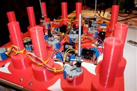
The images below shows some details of the final assembly
Every vertical moving part has an actuator built with a 28BYJ-48 geared stepper motor controlled by a LM298 motor controller; a total of 7 steppers + 7 controllers.
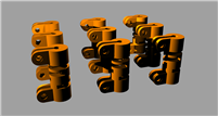
Stepper screw holder changes
As shown in the above images the original design for the stepper screw holder was 3D printer components too. The reason was the difficulty to find on the market similar metal components cheap and of the exact measure to fit the design. An easier solutions has been adopted instead as I have found strong and semi-flexible small hose: this material common use if for fuel and gasoline, so it is also resistant including temperature and solvents. And easy to manage and cut too. The images below shows in detail shows the final assembly.
Cabling the system
As show in the previous images, every stepper motor and controller are already connected together and fit inside the base. Then there are three different wiring solutions to be adopted: powering the system, controlling the motors and controlling the end-stop switches.
The final aspect as should appear (not yet boxed) to the visitor is shown in the image above.
Below the top view of the base with the stepper motors connected to the controllers and the powering cables. The motor controllers also provide a 5Vcc output and are used for all accessory powering than the motors.
End-stop switches
A special solution was needed to control the position of the mobile components, including the auto-zero finding. The three components that raise from the bottom has their zero point at the max height while the rest of the image mobile parts (the four blue ones) has their zero point laying on the white background surface. The startup sequence should include the initial auto zero position then parts are moved to their standby level. The form factor and the kind of end of stroke makes it impossible to use common end-stop switches as we are used to see in the 3D printers, mill machines etc.
Custom end-stop switches has been created with copper wire glued (with conductive glue) on both sides of the contact surfaces. The images below show ow the cabling has been setup on the bottom side of the white background.
The nut holder is also used as the end-stop contact. This means that the auto-zero is inverted respect the lower position, but this is a bare question of the software on the microcontroller.
Using the same method the three bottom components has been set with their end-stop custom switches.


Top Comments