element14 Community
element14 Community
    Register Log In
  • Site
  • Search
  • Log In Register
  • About Us
  • Community Hub
    Community Hub
    • What's New on element14
    • Feedback and Support
    • Benefits of Membership
    • Personal Blogs
    • Members Area
    • Achievement Levels
  • Learn
    Learn
    • Ask an Expert
    • eBooks
    • element14 presents
    • Learning Center
    • Tech Spotlight
    • STEM Academy
    • Webinars, Training and Events
    • Learning Groups
  • Technologies
    Technologies
    • 3D Printing
    • FPGA
    • Industrial Automation
    • Internet of Things
    • Power & Energy
    • Sensors
    • Technology Groups
  • Challenges & Projects
    Challenges & Projects
    • Design Challenges
    • element14 presents Projects
    • Project14
    • Arduino Projects
    • Raspberry Pi Projects
    • Project Groups
  • Products
    Products
    • Arduino
    • Avnet Boards Community
    • Dev Tools
    • Manufacturers
    • Multicomp Pro
    • Product Groups
    • Raspberry Pi
    • RoadTests & Reviews
  • Store
    Store
    • Visit Your Store
    • Choose another store...
      • Europe
      •  Austria (German)
      •  Belgium (Dutch, French)
      •  Bulgaria (Bulgarian)
      •  Czech Republic (Czech)
      •  Denmark (Danish)
      •  Estonia (Estonian)
      •  Finland (Finnish)
      •  France (French)
      •  Germany (German)
      •  Hungary (Hungarian)
      •  Ireland
      •  Israel
      •  Italy (Italian)
      •  Latvia (Latvian)
      •  
      •  Lithuania (Lithuanian)
      •  Netherlands (Dutch)
      •  Norway (Norwegian)
      •  Poland (Polish)
      •  Portugal (Portuguese)
      •  Romania (Romanian)
      •  Russia (Russian)
      •  Slovakia (Slovak)
      •  Slovenia (Slovenian)
      •  Spain (Spanish)
      •  Sweden (Swedish)
      •  Switzerland(German, French)
      •  Turkey (Turkish)
      •  United Kingdom
      • Asia Pacific
      •  Australia
      •  China
      •  Hong Kong
      •  India
      •  Korea (Korean)
      •  Malaysia
      •  New Zealand
      •  Philippines
      •  Singapore
      •  Taiwan
      •  Thailand (Thai)
      • Americas
      •  Brazil (Portuguese)
      •  Canada
      •  Mexico (Spanish)
      •  United States
      Can't find the country/region you're looking for? Visit our export site or find a local distributor.
  • Translate
  • Profile
  • Settings
PiCasso Design Challenge
  • Challenges & Projects
  • Design Challenges
  • PiCasso Design Challenge
  • More
  • Cancel
PiCasso Design Challenge
Blog PiCasso Design Challenge - Kinetic Art Mobile - Post 5 - Finally a PCB design.
  • Blog
  • Forum
  • Documents
  • Polls
  • Files
  • Events
  • Mentions
  • Sub-Groups
  • Tags
  • More
  • Cancel
  • New
  • Share
  • More
  • Cancel
Group Actions
  • Group RSS
  • More
  • Cancel
Engagement
  • Author Author: genebren
  • Date Created: 2 May 2019 3:45 PM Date Created
  • Views 2229 views
  • Likes 14 likes
  • Comments 21 comments
Related
Recommended

PiCasso Design Challenge - Kinetic Art Mobile - Post 5 - Finally a PCB design.

genebren
genebren
2 May 2019

Prior posts in the PiCasso Design Challenge:

PiCasso Design Challenge - Kinetic Art Mobile - Post 1

PiCasso Design Challenge - Kinetic Art Mobile - Post 2

PiCasso Design Challenge - Kinetic Art Mobile - Post 3 - Will it go round in circles????

PiCasso Design Challenge - Kinetic Art Mobile - Post 4 - Crash of the Death Star


Things have been crazy here lately.  I have been very busy trying to finish out the interior of my new workshop, while attempting to keep my PiCasso project moving.  I have stuck in a re-design cycle, where I have been moving components from board to board, trying to get everything to fit, in a reasonable way.  After multiple re-starts on the design, I think I have a workable design.


There are several different requirements on the design that have made it fairly difficult to find the right approach.  Here are a few of them:

  • uniform LED spacing to allow proper illumination of the orb and to allow some 'animations' based on different LED color patterns and sequences.
  • relatively high power (LED and Fan power)
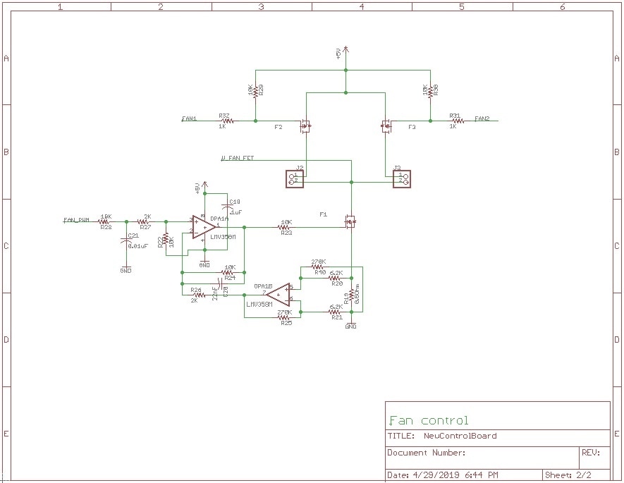
  • fan speed control (based on programmable constant current)
  • BLE transciever
  • Magnetic compass and accelerometer


I went through several trade off, trying to keep all of the high speed stuff on a single board, versus the space required for connectors should I distribute the components across multiple boards.  Here is what I ended up with:

imageimage

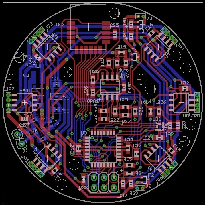
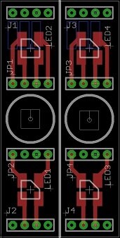
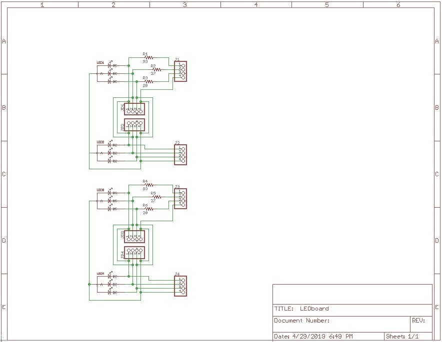
The Main PCB is riddled with 12 - 0.1" holes to allow additional air flow, through the board, into the fans below (there will also be some airflow around the board edges).  I will be trimming the PCB into a circle, as my PCB vendor (lower cost) only allows for rectangular boards.  The LED boards are sort of a universal design that will be connected to the main PCB, providing pairs of  LEDs along the circumference of orb and a single LED providing downward lighting (right angle mounted, hacked LED PCB).  This will provide me with 18 - fully programmable RGB LED to illuminate the sides and bottom of the orbs.


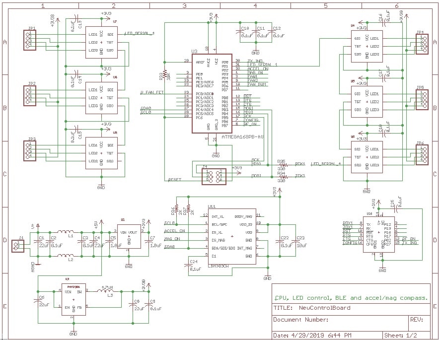
Here are the schematics of the main controller and LED board:

imageimage

image


I will need to send these boards of soon and order up parts for the board, but for now, I heading out to the workshop to install drywall and lighting.


Thanks for reading along.  I hope that I can get this project moving along a bit faster, so I can meet the deadlines.


Thanks,

Gene

  • Sign in to reply

Top Comments

  • genebren
    genebren over 6 years ago in reply to dubbie +6
    Thanks Dubbie. I have been laying out PCBs for quite a while (45+ years). I go back to self etched boards, using resist pens, tape or photoresist film (1970's), through many different design packages.…
  • genebren
    genebren over 6 years ago in reply to ralphjy +6
    Ralph, I do all of my assembly by hand (under a microscope). I do not have a reflow oven yet, but it is on my wish list for future tool purchases. The LSM303C (3D accelerometer and 3D magnetometer) is…
  • dubbie
    dubbie over 6 years ago +5
    Gene, Impressive PCB design. I've done a few simpler ones in my time but nothing like this. Dubbie
Parents
  • ralphjy
    ralphjy over 6 years ago

    PCB looks great. How are you going to do the SMD assembly?  Are you going to use paste with a stencil?  I don’t recall whether you have a reflow oven.


    Like Frank I’ve never done well cutting circular boards but I will admit to using a belt sander to clean things up.  Made quite a mess.


    Hope your airflow works out.  How much current do you think you’ll end up putting through the slip rings?


    Ralph

    • Cancel
    • Vote Up +4 Vote Down
    • Sign in to reply
    • More
    • Cancel
  • genebren
    genebren over 6 years ago in reply to ralphjy

    Ralph,


    I do all of my assembly by hand (under a microscope).  I do not have a reflow oven yet, but it is on my wish list for future tool purchases.  The LSM303C (3D accelerometer and 3D magnetometer) is a very tight package, LGA device, so hand soldering is going to be very tough.  In the past, on similar packages, I have had some luck with using larger than normal PCB pads, where I can apply the solder outside of the package, and flow it under the device (lots of flux), so this is my plan.


    Cutting PCBs is quite difficult as the material is quite hard.  I have done this before (see reply to Frank), so I hope to be able to shape this boards without too much trouble.  Thinking about this, I might want to order a few extra boards to practice on, or to have as backups.


    The airflow is a really good question.  I had planned on creating a 'keep out' space in the center of the board for the holes, but abandoned this as I ran out of real estate.  The holes that I did place, ended up to be sort of a after thought, as once I left of the 'keep out' region in the center, I completed forgot about the holes.  I had started to write-up a blog entry on the PCBs (capturing images), when I suddenly remembered that I had wanted some holes (getting old sucks).


    The current is still a question.  I have planned on 5mA per segment, per LED, which which comes to 270mA, plus 150mA for the fan (or 300mA if I switch on both fans).  This leaves me at 420-570mA.  Hopefully the 5mA LED current will give me enough illumination on the orb, or i might have to push the current a bit.  The real problem, comes as each arm is going to be daisy chained, to the top most slip ring will see all the current.  With five arms, I am already pushing 2A+.


    Thanks,

    Gene

    • Cancel
    • Vote Up +6 Vote Down
    • Sign in to reply
    • More
    • Cancel
Comment
  • genebren
    genebren over 6 years ago in reply to ralphjy

    Ralph,


    I do all of my assembly by hand (under a microscope).  I do not have a reflow oven yet, but it is on my wish list for future tool purchases.  The LSM303C (3D accelerometer and 3D magnetometer) is a very tight package, LGA device, so hand soldering is going to be very tough.  In the past, on similar packages, I have had some luck with using larger than normal PCB pads, where I can apply the solder outside of the package, and flow it under the device (lots of flux), so this is my plan.


    Cutting PCBs is quite difficult as the material is quite hard.  I have done this before (see reply to Frank), so I hope to be able to shape this boards without too much trouble.  Thinking about this, I might want to order a few extra boards to practice on, or to have as backups.


    The airflow is a really good question.  I had planned on creating a 'keep out' space in the center of the board for the holes, but abandoned this as I ran out of real estate.  The holes that I did place, ended up to be sort of a after thought, as once I left of the 'keep out' region in the center, I completed forgot about the holes.  I had started to write-up a blog entry on the PCBs (capturing images), when I suddenly remembered that I had wanted some holes (getting old sucks).


    The current is still a question.  I have planned on 5mA per segment, per LED, which which comes to 270mA, plus 150mA for the fan (or 300mA if I switch on both fans).  This leaves me at 420-570mA.  Hopefully the 5mA LED current will give me enough illumination on the orb, or i might have to push the current a bit.  The real problem, comes as each arm is going to be daisy chained, to the top most slip ring will see all the current.  With five arms, I am already pushing 2A+.


    Thanks,

    Gene

    • Cancel
    • Vote Up +6 Vote Down
    • Sign in to reply
    • More
    • Cancel
Children
No Data
element14 Community

element14 is the first online community specifically for engineers. Connect with your peers and get expert answers to your questions.

  • Members
  • Learn
  • Technologies
  • Challenges & Projects
  • Products
  • Store
  • About Us
  • Feedback & Support
  • FAQs
  • Terms of Use
  • Privacy Policy
  • Legal and Copyright Notices
  • Sitemap
  • Cookies

An Avnet Company © 2025 Premier Farnell Limited. All Rights Reserved.

Premier Farnell Ltd, registered in England and Wales (no 00876412), registered office: Farnell House, Forge Lane, Leeds LS12 2NE.

ICP 备案号 10220084.

Follow element14

  • X
  • Facebook
  • linkedin
  • YouTube